Hooking up the heat on this '73 I just purchased. Never understand why heat is disconnected on street cars. But anyway...
Flapper boxes reconnected and in good condition, cables in good working order and I made a block off plate for the passenger side "riser" (that goes up through the engine tin.
So I have heat to the cabin from the main engine fan, cannot get the aux blower motor to engage. Electrical connections good in engine compartment, so I am hoping it is just disconnected at the switch/lever in the cabin, or perhaps a fuse.
What's the best way to service this lever? I searched on "heat", and a few other keywords but got mostly discussions about SS heat exchangers (which I have). Looking for the fastest way into the tunnel to see if the lever is connected to the harness for the aux fan.
All help appreciated.
Full Version: Heater Aux blower
unbolt the lever assembly and ensure the wire is on. iirc the lever provides the ground for the fan. while the lever controls the flapper boxes, at the max of the lever travel is when a little nub on the assem makes the contact.
QUOTE(rhodyguy @ Jan 6 2015, 05:20 PM) 
unbolt the lever assembly and ensure the wire is on. iirc the lever provides the ground for the fan. while the lever controls the flapper boxes, at the max of the lever travel is when a little nub on the assem makes the contact.
 It's probably either the ground wire missing at the lever or a failed relay on the relay board. When you unbolt the lever, pull the assembly gently out of the tunnel a few inches and find the ground wire, if possible. It may have come disconnected and might be dangling in the tunnel (I had to use a small mirror and dental pick to fish mine out). Find/clean that connection.
 If it's grounded at the lever, check Relay 55. Swap in a known good one into that and see if that works.
The heater lever on mine had the electrical contact broken off, so had to get a new lever assembly. Be careful when you pull the lever off !
Finally got to inspect the lever (remove seats, backpad, console, carpet, etc). There is a green with white tracer wire nicely connected to the lever, and the "nub" at the far end of lever travel. I'd think a ground wire would be the ubiquitous VW/Porsche brown?
Anyway, will check relay 55 next (gotta find it first).
Anyway, will check relay 55 next (gotta find it first).
Yes, but I believe that is in fact the correct wire and color. The relay should be the one furthest back, IIRC. I'll find the link to the relay board diagram on Pelican.
EDIT: Here it is (at least for the '73 - the '71 is also on Pelican): Relay Board.
It's relay 55. That green/white wire is the same one connecting to the 14 (?) pin connector at the front of the relay board on Pin 9, I believe. Through the board it connects to relay 55 at pin 86.
EDIT: Here it is (at least for the '73 - the '71 is also on Pelican): Relay Board.
It's relay 55. That green/white wire is the same one connecting to the 14 (?) pin connector at the front of the relay board on Pin 9, I believe. Through the board it connects to relay 55 at pin 86.
Thanks for the link, I believe I have a good spare relay.
If it still doesn't work after swapping out the relay, remove the blower and directly (and carefully) connect 12v to the leads and see if it will run at all. Don't know what kind of shape yours is in, but I had to clean mine pretty well to get it to move.
Good luck.
Good luck.
I imagine I will remove it and clean it anyway. I have had to deal with 911 footwell blowers many times, and a good cleaning always gets them spinning freely.
Thanks again.
Thanks again.
Swapped relay 55 with another relay from my pile of spares (unknown condition). Checked all fuses visually, all OK. Removed blower motor and cleaned (it spun freely). Hooked it up to a 12V power supply on the bench, works just great. Put it all back together, key in "on" position, lever all the way back, no blower motor.

What am I missing?
What am I missing?
Your fan works, so it's a matter of getting it power and ground. Time to check continuity and connections. I would do a couple of things:
1. Did you CLEAN the ground connection at the lever? That's worth doing so you know you do have a good ground (if you did not when you were in there).
2. With ignition on and heater lever in the up position (all the way), use a voltmeter or test light and see if you have power at the green lead on the blower motor (ground the test light/voltmeter to the battery negative post). If you do, then I believe the ground lever, the relay board, the relay, and the other connections are good. Check the actual blower motor ground brown wire to its grounding point (I'm not sure if mine is stock or not -- it's been grounded to a dedicated ground point off the block -- it's effective, but it doesn't look original to me).
3. Most likely, you do not. So your issue is probably somewhere in one of the connections on the relay board or back at the heater lever. Without the ignition on, test continuity from relay pin (the hole) 87 to connector pin 11 on the 14 pin connector at the front of the relay board (if I'm reading the diagram correctly). If you have any doubts about the continuity clean the connection points at the relay, at the 14 pin connector, AND at the 12 pin connector on the rear right side of the board - pins 11 and 10 are the operative ones here I think.
4. Are you actually getting a good ground to the relay? With ignition on and the heater lever in the up position, do you have 12v at pin 87 of the relay? If not, the issue is on the relay board to the 14 pin connector or from there to the grounding point at the lever.
That's pretty much it. This all assumes the relay you used was truly a good relay. Anyone else have any thoughts?
do your headlights work? if so, use one of those relays.
QUOTE(sdoolin @ Jan 9 2015, 07:20 AM)
Swapped relay 55 with another relay from my pile of spares (unknown condition). Checked all fuses visually, all OK. Removed blower motor and cleaned (it spun freely). Hooked it up to a 12V power supply on the bench, works just great. Put it all back together, key in "on" position, lever all the way back, no blower motor.
What am I missing?
Broken wire maybe? Take the wire loose from the lever and the fan. check for continuity, end to end of that wire.
If you take the wire off of just the fan, pull the lever to make contact, you could then check continuity from the fan end of the wire to a metal point on the car. That would tell you that it is grounding. and the wire is not broken.
make sure the nub and the little brass springy piece the wire is on at the lever are connecting, and that they are clean.
I would have to dig deeper on the 12v side with the diagram, but you need to go thru all the wiring and connection points for the device that is not working.
Since the fan works on the bench, The problem must be in the car.
Good luck
Edit: cleaning on electrical stuff, can mean a couple things. Clean, like wipe the dirt and grease off is one.
The other would be to SHINE, like with a scotchbrite pad or emery cloth or high grit sand paper or small file. Shine up both sides of a connection.
Thanks so much for the responses. While I am comfortable and knowledgeable with engines, brakes, chassis/suspension and "mechanical" stuff in general, wiring has always been "magic" to me.
I'll try all of what y'all have suggested here sometime in the next week (out of town this weekend) and hopefully will find a solution. Will report back.
I'll try all of what y'all have suggested here sometime in the next week (out of town this weekend) and hopefully will find a solution. Will report back.
This is a good electrical challenge then from which to learn. The electrics of the heater blower are pretty straightforward and will help you understand how this stuff works on the 914. If you don't have them already, get a voltmeter (or multimeter) or at least a test light. You'll definitely need them again. Good luck.
QUOTE
The other would be to SHINE, like with a scotchbrite pad or emery cloth or high grit sand paper or small file. Shine up both sides of a connection.
Agree - my experience with the VW Bus, Beetle, and countless vintage bikes has tought me to "shine" these connections. Steel wool, Scotchbrite, 400 grit SP, brass brush, even polish sometimes.
QUOTE
This is a good electrical challenge then from which to learn. The electrics of the heater blower are pretty straightforward and will help you understand how this stuff works on the 914. If you don't have them already, get a voltmeter (or multimeter) or at least a test light. You'll definitely need them again. Good luck.
Agree also. I have multimeter and test light. They are in a drawer of the toolbox I use very rarely. Gonna get them both out later today.
I had issues with my headlight motor. I took a long wire and ran it straight from the switch to the motor. It worked telling me the wire was bad. I found the break when I pulled it out to be replaced....
Try touching the wire on the heater lever directly to chassis to see if the fan turns on.
If you do this with the ignition on (you want to disconnect the red wire from the coil to keep from damaging the points/pertronix/coil while the engine isn't running) you should be able to hear the relay click on.
Also I think there's a fuse on the relay board for the fan. Check the fuse and clean the fuse contacts.
Got free of work so went to the barn to check a few things (I have not gotten to ALL of y'alls suggestions)...
Key switched on, lever all the way back. Touch test light to green wire from harness at fan - no light. Touch test light to brown wire from harness at fan - LIGHT! There is a yellow and a brown wire coming from the fan. These have been hooked up as:
Fan Yellow - Harness Green
Fan Brown - Harness Brown
Not sure if this helps me? Apologies for my ignorance (ask me _anything_ about a 76 VW Bus though (except how to troubleshoot aux heater fan))...
I'm trying to wrap my head around this. When using your test light, how are you grounding it? (Where are you connecting the alligator clip of the test light?)
Grounding the test light to a multi point ground inside engine compartment, just behind relay box (drivers' side).
Sorry, that brown wire from the harness should be connecting to the multi-point ground (I believe by the relay where you describe it). Are you doing a continuity test or a voltage test with that test light? I was assuming voltage test....
I will take a few pics, I don't see how the brown wire from the harness can possibly be connected to the multi point ground (unless I am missing a wire). That brown wire from the harness is "sheathed" together with the green harness wire and the sheathing stops just short of the fan connection leads.
I'll shoot a pic.
Working on shifter bushings too. Oh man did I find a screwed up ball/socket bush...
I'll shoot a pic.
Working on shifter bushings too. Oh man did I find a screwed up ball/socket bush...
A picture would be good and may help sort out what you mean. Check the wiring diagram: '73 Wiring Diagram.
Item 65 is the blower motor. The brown wire from that leads to 82 which is a multiple point ground. The two wires from the fan should lead back into the wiring harness and go their respective destinations (brown to the multi-point ground and green to pin 11 on the relay board 14 pion connector.
Item 65 is the blower motor. The brown wire from that leads to 82 which is a multiple point ground. The two wires from the fan should lead back into the wiring harness and go their respective destinations (brown to the multi-point ground and green to pin 11 on the relay board 14 pion connector.
Here's a pic.
Click to view attachment
I guess with my test light I am just testing continuity? So if I connect alligator lead to body/ground and other end to this brown wire, I am simply confirming good ground?
Click to view attachment
I guess with my test light I am just testing continuity? So if I connect alligator lead to body/ground and other end to this brown wire, I am simply confirming good ground?
QUOTE(sdoolin @ Jan 9 2015, 02:02 PM)
I guess with my test light I am just testing continuity? So if I connect alligator lead to body/ground and other end to this brown wire, I am simply confirming good ground?
That's what I am thinking, yes. Do you have an actual voltmeter or voltage test light you can use (assuming that what you did up to now was test continuity)?
I have a multi-meter. It's use is a mystery to me. But lets say I put it between the green harness lead and the battery, I should get 12 v (ish)?
Yes, that's what I'm hoping (or that's one test to perform). We now know you have a good ground at the fan. If you set up your multimeter correctly (switch it to DC Voltage, connect the leads to the proper spot), you want 12 V when one lead is connected to the green wire and the other lead connected to a good ground (or -12V is fine too if you have the leads switched) WITH ignition on and heater lever up.
I'm guessing you will NOT have 12V. That's the issue. And the breakdown is one of several potential places:
1. Bad ground at lever or broken wire (the green/white one) to the relay board.
2. Bad/dirty connections on the relay board (at the 14 pin connector or the 12 pin connector).
3. Broken fuse or bad fuse connection (as Spoke pointed out) on the relay board.
4. Bad relay 55 or bad relay connections (e.g., pins 30, 86, 87 etc.).
5. Bad relay board (traces bad)
6. Broken or bad green wire from relay board to fan.
It's a good idea to remove and polish up ALL those connections.
Once you do that we can figure out how to isolate where the problem is.
OK, 0V when multi-meter hooked up between battery and green harness lead. Double checked key on and heater lever all the way rearward.
So - onto the other tests (and shift linkage work).
Rob - thanks so much. Will see if I can get through the rest of your "list".
So - onto the other tests (and shift linkage work).
Rob - thanks so much. Will see if I can get through the rest of your "list".
QUOTE(sdoolin @ Jan 9 2015, 06:39 AM)
Thanks so much for the responses. While I am comfortable and knowledgeable with engines, brakes, chassis/suspension and "mechanical" stuff in general, wiring has always been "magic" to me.
I'll try all of what y'all have suggested here sometime in the next week (out of town this weekend) and hopefully will find a solution. Will report back.
All electrics are magic; how else would smoke make things light up and so forth? We all know that when the smoke leaks out of the wires, the things stop working!
QUOTE(sdoolin @ Jan 9 2015, 02:27 PM)
OK, 0V when multi-meter hooked up between battery and green harness lead. Double checked key on and heater lever all the way rearward.
So - onto the other tests (and shift linkage work).
Rob - thanks so much. Will see if I can get through the rest of your "list".
You'll get there. It's a good learning experience. The good news is we know your blower works. Assuming you don't have a broken wire somewhere it's most like a dirty connection somewhere on the relay board.
Make sure you're dealing with the correct wires in the cabin. The defroster is similar....
Power comes from the blower relay (rearmost relay, pin 87) to the green wire plugged into the fan. Power (+12V) should be there when the key is on and the "DEFROST" lever is pulled all the way up. The brown wire plugged into the fan should be grounded at all times.
The blower relay gets power from one of the relay board fuses, which in turn gets it from (terminal #30) the battery. It should have +12V all the time. Check at the fuse (the rear of the two fuses on the relay board) for +12V; check both sides of that fuse for +12V in fact.
The blower relay gets switched off and on by having voltage across pins 85 and 86. In this case, pin 85 (the right-side pin) should have power any time the key is on. Check for +12V then.
Pin 86 (the left-side pin) should be GROUNDED when the defrost switch is all the way up. Check for continuity with ground.
If 30 has power, 85 has power, and 86 is grounded, then pin 87 of the relay should have power. You can unplug the 12-pin connector at the right-rear of the relay board and check for +12V at pin #11, the left-rear pin.
The most common cause of the blower not running is that the green/white wire that eventually winds up going into pin 86 of the relay is not getting shorted to ground.
--DD
Houston - we have success!
Wire from lever to 14 point multi-plug (pin 9) in engine compartment not broken, I verified continuity.
This relay board looks like it has been hot before, not like in a fire, but plenty hot. So picked the best looking relay board from my pile of spares. Cleaned all contact points (scotchbrite, wire brush, etc).
On the relay board, verified continuity between 14 point multi-plug pin 9 and relay 55 socket 86. Also verified continuity between 14 point multi-plug pin 14 through fuse all the way to relay 55 socket 30.
Also on relay board verified continuity between 12 point multi-plug pin 11 and relay 55 socket 87, and pin 7 to relay 55 socket 85.
I think that all matches up with the diagram from Pelican (I am working on a '73).
Ensured good ground at the lever (sanded some paint away from the mounting point, and sanded lever mount).
Reconnected everything and Wala! I now have a functional (if not loud) aux heater blower.
I actually think it was the power side connection it the fan all along. The OE connecter "shield" on that wire appears also to have been hot somewhere in the past so it is somewhat melted and mis-formed. I think this kept the connection from being fully made. I noticed that with a pair of needle-nose pliers I got a lot more "meat" on that connection.
Glad I verified it all and thanks everyone for the responses and help.
Now, to find fresh air hose of the right diameter and length to hook up the passenger side to the aux blower. I have the dual outlet plastic bit for the fan, just need (OE style) hose.
Y'all are great, and thanks again.
I added the dual hose kit from Auto Atlanta. Without it, my defrost barely worked. Had to do a little mod getting the dual outlet part attached. The hose was long enough to cut in two pieces for both heat exchangers Zip tied the long hose across the engine compartment. Looks very tidy.
Glad you were successful! Now you have the challenge of making sure the air passages are as sealed as possible and not blocked by, oh, I don't know, rodent leftovers. 
Good luck!
Good luck!
I'm trying to troubleshoot this same problem in my '74. I found the green/white wire under the lever was not connected (female spade). But what does it connect to? Some place on the lever itself?
Yes. On the underside of the lever.
--DD
--DD
QUOTE(Dave_Darling @ Dec 8 2016, 06:16 PM)
Yes. On the underside of the lever.
--DD
Thanks for the reply DD. I had figured it out in the meantime, although I missed the part about disconnecting the cables so I had quite a time wrestling the connection back on to the spade. Of course that didn't solve my problem, so I'll have to go back and re-read this thread to figure out the electrical gremlin. I had already checked that the blower itself works and swapped out relay to see if that was bad. Fuses are good too. Ah well, I still have fun solving these riddles, especially with World help at my fingertips!
I am no electrician, but I would think the lever wiring design is basic.
12v goes to the fan. when the lever is pulled to it's high point the wire on the lever closes the electrical loop, as it grounds that circuit and the fan starts.
So if you have 12v at the fan, the only other thing would be the wire to the lever. Check it for continuity (broken wire). I probably over simplified, but is all sounds good....
You also need to check the relay board. Specifically, make sure the far back relay is seated and serviceable, and make sure the connectors on the board (and fuses) are good.
The wire on the lever ends up grounding the relay through the relay board. Then the blower can get 12v.
The wire on the lever ends up grounding the relay through the relay board. Then the blower can get 12v.
QUOTE(malcolm2 @ Dec 9 2016, 06:02 AM)
I am no electrician, but I would think the lever wiring design is basic.
12v goes to the fan. when the lever is pulled to it's high point the wire on the lever closes the electrical loop, as it grounds that circuit and the fan starts.
So if you have 12v at the fan, the only other thing would be the wire to the lever. Check it for continuity (broken wire). I probably over simplified, but is all sounds good....
I had this same exact problem in my car. I think it is in part a bad design. Over time the harness connector pin contacts become loose causing enough reaistance and heat to melt the long lead that grounds the relay.
Cleaning all the connectors along with a rehabed traces on the board fixed mine as well.
sdoolin, would you mind taking a broader pic of the engine bay as it relates to the heater system....I am putting mine back together never having seen it together in the first place. Much thanks, Grant
QUOTE(malcolm2 @ Dec 9 2016, 06:02 AM)
12v goes to the fan. when the lever is pulled to it's high point the wire on the lever closes the electrical loop, as it grounds that circuit and the fan starts.
I don't believe that is correct.
The lever grounds a wire from the heater blower relay, turning the switch inside the relay on and sending power to the heater blower. The blower motor is grounded all the time, so when power is sent to the positive terminal of the blower it runs.
--DD
QUOTE(Dave_Darling @ Dec 9 2016, 11:20 AM)
QUOTE(malcolm2 @ Dec 9 2016, 06:02 AM)
12v goes to the fan. when the lever is pulled to it's high point the wire on the lever closes the electrical loop, as it grounds that circuit and the fan starts.
I don't believe that is correct.
The lever grounds a wire from the heater blower relay, turning the switch inside the relay on and sending power to the heater blower. The blower motor is grounded all the time, so when power is sent to the positive terminal of the blower it runs.
--DD
Dave... is correct. Didn't mean to quote the previous post.
The wire to the lever grounds the relay with a tang on the lever...IIRC.
Problem with that is that in the pin connector from the harness there are hot wires....a nice situation for a short.
Malcolm, the blower is operated by a relay, the switch on the heater lever is the switch leg of the relay.
2 point sidebar - 1 The best way to get heat is once it gets warmed up, keep the engine above 3000rpm and you should have good heat. The blower was designed for times of low engine speed, like in traffic.
2 I've always wanted to hook up dual fans for double the defrost power.
2 point sidebar - 1 The best way to get heat is once it gets warmed up, keep the engine above 3000rpm and you should have good heat. The blower was designed for times of low engine speed, like in traffic.
2 I've always wanted to hook up dual fans for double the defrost power.
Okay, sorry, but I'm now I'm confused. So I reconnected the wire at the lever. I tried swapping out the relay with one from a headlight that I know works. I put 12 V power directly to the fan motor and it worked. What should I do next to troubleshoot? Not great with electricity, so if you could put it in layman's terms?
The lever should have a brown wire with a spade connector on it.
When you pull the heater lever up to an extent it simply provides a ground for the fan motor....simply put.
The ground wire and trace runs through the regulator plate. Pin 10.
If the wire from pin 10 on the harness which plugs into the plate rings out for continuity...then it is not the wire. Then check the ground wire to the ground point on the body for continuity and contact on the chassis.
If the wires check out the check the traces on the regulator plate.
You will need a wiring diagram to understand this. It isba simple circuit.
Good luck......post a pic of the ground lead inside the car for us.
In my view this wasba bad design because the ground trace runs right next to hot traces and leads. But then again nobody expected these cars to last this long.
QUOTE(914_teener @ Dec 12 2016, 11:03 AM)
The lever should have a brown wire with a spade connector on it.
When you pull the heater lever up to an extent it simply provides a ground for the fan motor....simply put.
The ground wire and trace runs through the regulator plate. Pin 10.
If the wire from pin 10 on the harness which plugs into the plate rings out for continuity...then it is not the wire. Then check the ground wire to the ground point on the body for continuity and contact on the chassis.
If the wires check out the check the traces on the regulator plate.
You will need a wiring diagram to understand this. It isba simple circuit.
Good luck......post a pic of the ground lead inside the car for us.
Am I reading the diagrams correctly? Based on the wiring diagram I see it slightly differently (although I could be wrong - certainly have been before). I agree with the overall description, but I want to make sure the wires/connections are correct to avoid confusion (or see if I'm the one confused
 )
)I believe the wire at the switch (or heat lever) is green with white stripe. Yes, it connects to a tab on that lever. When the lever is pulled fully, it grounds as follows: to pin 9 on the 14 pin connector (the one at the front of the relay board), through the relay board, to pin 86 on that far back Relay. The Relay is charged and provides 12v from pin 87 on Relay through relay board to pin 11 on the 12 pin connector (the one on side near back of relay board). There is a jumper from pin 11 to pin 10 on the 12 pin connector that then carries the 12v back to pin 11 on the 14 pin connector. That is a solid green wire that is connected to the actual heater fan motor.
Short version: green/white wire grounded at lever completes ground to relay pin 86 on relay board through pin 9 on 14 pin connector. 12v then travels from relay pin 87 BACK to 14 pin connector at pin 11 and out to motor blower on solid green wire. Fan motor already grounded and "whiirrr." It goes, and a modest amount of air comes out.
In addition to the wiring diagram in link above (heater switch/lever is 37 in diagram and motor itself is 65), here's the relay board diagram (the one that has 14 pin connector I/O):
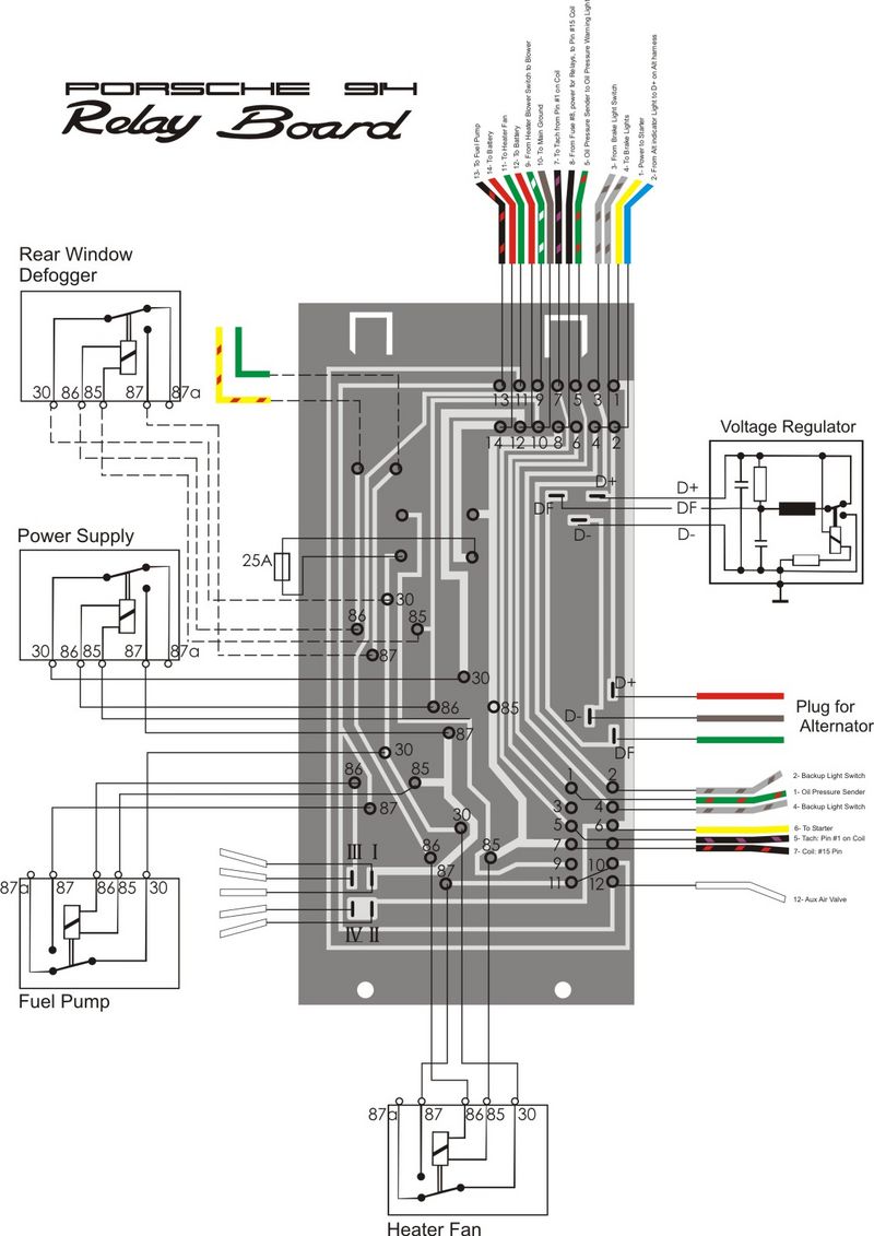
So to troubleshoot, I agree with 914_teener. Make sure you have continuity from green/white wire at lever to pin 86 position where the heater relay goes. That is the pin the farthest to the driver's side, I believe. Then make sure you have continuity from pin 87 position (the one the farthest to the rear of car) to the hot wire on the heater blower motor. Of course the relay needs to be good, the fuses, and the motor itself needs to be grounded. Make sure you're getting a real ground at heater lever.
This is a "lo-fi" version of our main content. To view the full version with more information, formatting and images, please click here.