EDIT: So you don't have to go to the end of the thread. Hopefully this will help someone. Especially if I am not wrong.
I found a pair of diodes in the gauge harness of my '72, located behind the brake warning light above the fuel gauge, Since I was rewiring for a triple gauge I wanted to know what they did. I have since figured it out. It is unique to the '72, since one diode was present earlier and then disappeared as another was added. Only the '72 has both. So I had to look at the '71 and the '73 diagrams to get a good answer. The '72 diagrams are blurry. So below is what I tracked down. Let me know all you engineers in the mist if I am on the correct track.
Click to view attachment
One of the most puzzling things to me is that Porsche often uses the transistor symbol on a relay when they don't want to tell you about what is inside. I now think that the transistor symbol means just a symbol for an NPN transistor. Overcomplicated that one, I did.
I also just realized that the system would prevent the seatbelt warning system from going into effect until the parking brake was released with an unbelted occupant. That now tells me why R3 is there and why a transistor.
Thanks everyone who chimed in, and if there are mistakes please correct them! END EDIT
I am trying to make the gauges on my six conversion easy to disconnect with only one or two plugs. Now I want to wire my triple gauge and that includes the brake light. I have brown wires with white stripes that appear to go to switches to ground:
The hand brake switch.
The master cylinder shuttle switch.
The wire to the brake reservoir switch that is activated by low fluid (not normally connected).
A wire out to the seat belt warning light.
I have a wire to the alternator blue with a diode. I think this turns the brake light on momentarily at start up.
Then there is an identical diode between the brake light and a brown and white striped wire. I am thinking this goes to the seatbelt light, but haven't traced it. What does the diode do, and how does the seat belt figure into this. I see it on a diagram, but cannot figure out what current the diode is meant to block.
Thanks folks!
Full Version: Why the diode on the '72?
I'm guessing your car is a 74. Diode is so multiple inputs can use the warning light on the dash without creating a ground loop causing the lamp to blink all the time. You need this if: your seat belt warning system is operational or your brake pressure warning system is operational or your parking brake handle warning system is operational.
If any of these systems are operational keep it. If they are not operational AND you know how to remove the systems correctly, remove them. If you want the systems to work correctly, keep them.
If any of these systems are operational keep it. If they are not operational AND you know how to remove the systems correctly, remove them. If you want the systems to work correctly, keep them.
QUOTE(Mike Bellis @ Aug 17 2015, 05:27 PM) 
I'm guessing your car is a 74. Diode is so multiple inputs can use the warning light on the dash without creating a ground loop causing the lamp to blink all the time. You need this if: your seat belt warning system
I did not receive the seattcheshe carutcuitry through
is supposed to be going on with the switches or diagrams. In other words, I am trying to wing it and am lost.
Can you expand a bit. I have seen your posts and believe them to be archival. In other words am trying to sweet talk you into explaining more. Also consider that taken with your previous revelations they can be used to explain the whole ball of wax. Which is a portion of worth. Please elaborate and become a person of greatness.
Thanks,
Warr
QUOTE(worn @ Aug 17 2015, 05:43 PM)
QUOTE(Mike Bellis @ Aug 17 2015, 05:27 PM)
I'm guessing your car is a 74. Diode is so multiple inputs can use the warning light on the dash without creating a ground loop causing the lamp to blink all the time. You need this if: your seat belt warning system
I did not receive the seattcheshe carutcuitry through
is supposed to be going on with the switches or diagrams. In other words, I am trying to wing it and am lost.
Can you expand a bit. I have seen your posts and believe them to be archival. In other words am trying to sweet talk you into explaining more. Also consider that taken with your previous revelations they can be used to explain the whole ball of wax. Which is a portion of worth. Please elaborate and become a person of greatness.
Thanks,
Warr
Thanks a lot ipad.
I was trying to say that I understand circuitry, but do not understand how this was supposed to work. I expect that the diode was meant to block a positive 12v signal caused by the seat belt system from getting into the brake warning loop. Still, I do not see quite how that would have occurred. Can you explain??
The diode allows current flow in only one direction. On the diode symbol, the line is negative and the triangle is positive. If placed this direction in the circuit, current will flow negative to positive. It cannot flow the other way.
In a DC circuit, current will flow without a true positive or negative. Example: one point of the circuit is 10V and the other point is 12V, current will naturally flow from 10V to 12V due to the difference in potential. 10V is more "negative" than 12V in your car.
I do not have the circuit in front of me but the diodes are in place to prevent the difference in potential in the circuit from reverse flow current that would trigger your flashing light.
Diodes also drop about 0.7V and are sometimes used for this in a circuit.
Zener diodes block current flow until the voltage potential gets above a designed threshold. It then shunts the voltage off above that threshold. Example: On a turbo car MAP sensor reading 0-5V, At stock boost the sensor may read 5V @ 10psi. I then add a boost controller increasing the boost to 20psi. In simplistic theory, the sensor would read 10V, but the ECU would throw the car into limp mode. I install a 4.7V zener in the circuit and shunt away any voltage above that level keeping the ECU from seeing the wrong signal.
LED, Light Emitting Diodes work similar to a standard diode but when you forward bias the diode it light up. Forward bias is the term used when the diode is in the circuit flowing current.
Did I miss anything? How bout it you EE's out there?
Chu got it, mang ...
Thanks Mike,
Despite my gibberish I knew all of the above, although it was stated better than I could. There are two diodes on my 72. One appears to be there to allow a circuit to ground at start so as to test the brake warning light. It is connected to the alternator wire, which would be equal to zero volts until spinning. Then it would come up and the light would stop. That would be cheap and easy and wouldn't short the alternator diodes through the brake warning system.
The other one goes to the "relay" for the seatbelt warning. The seatbelt wiring has been removed. But as you say, before you muck with it you want to understand it. My guess is that under some circumstances that relay will provide a ground to light up the brake warning light. The wire is brown white like all the switch wires going to ground. Here I mean the car body or a brown wire as ground or negative battery post.
The presence of the diode indicates to me that sometimes that brown white wire Linking the warning brake light to the relay for seat belt warning is plus 12 rather than ground and the diode is there to prevent that flow. Perhaps if the parking brake was still engaged the designers did not want current flow from the relay directly to ground.
My biggest problem in figuring this out is I do not have a diagram for the internal circuitry of the seat belt warning relay. It just shows a transistor symbol.
I appreciate the posts a lot. Anyone understand the innards of the seatbelt warning box?
QUOTE(Mike Bellis @ Aug 17 2015, 07:14 PM)
The diode allows current flow in only one direction. On the diode symbol, the line is negative and the triangle is positive. If placed this direction in the circuit, current will flow negative to positive. It cannot flow the other way.
Diodes also drop about 0.7V and are sometimes used for this in a circuit.
Z
Quick addition. Forward voltage drop is .65v so, just as expected.
Then with current direction. I think of electrons in the metal valence cloud flowing. That flow of electrons as current fits your description of current and the diode symbol. However engineers like thinking of current as positive to negative, sort of like the movement of spaces where the electron just was. That does not seem to match the description above. Which did you mean? Thanks! Nice to have a resident electrician here!
QUOTE(worn @ Aug 19 2015, 03:57 PM)
However engineers like thinking of current as positive to negative, sort of like the movement of spaces where the electron just was.
Unless you were a military trained engineer. As I understand it the Army, at least at one time, taught current flow as negative to positive. All basic DC circuit classes I know of in the civilian world teach current flow as positive to negative. Take your pick, as long as you are consistent and define your terms.
Gary
QUOTE(stinkindiesel @ Aug 19 2015, 02:58 PM)
QUOTE(worn @ Aug 19 2015, 03:57 PM)
However engineers like thinking of current as positive to negative, sort of like the movement of spaces where the electron just was.
Unless you were a military trained engineer. As I understand it the Army, at least at one time, taught current flow as negative to positive. All basic DC circuit classes I know of in the civilian world teach current flow as positive to negative. Take your pick, as long as you are consistent and define your terms.
- The conventional engineering notation is that current flows from positive to negative.
- The scientific electron current flow is that current flows from negative to positive.
Instead of thinking like an engineer where the electrons move into the empty space (holes) think of it as the holes moving the opposite direction.

QUOTE(SirAndy @ Aug 19 2015, 04:55 PM)
- The conventional engineering notation is that current flows from positive to negative.
- The scientific electron current flow is that current flows from negative to positive.
Instead of thinking like an engineer where the electrons move into the empty space (holes) think of it as the holes moving the opposite direction.

And I'll add a bit about the wire that runs to the alternator.
That wire will be +12VDC when the ignition is on, but the engine is not running (source being the dash power).
The alternator light will be lit right now as current flows from the +12VDC in the dash through a diode & through the bulb and then through the excitation winding in the alternator, to ground.
So current is flowing though the alternator excitation winding, but it is not spinning.
Once you start the engine and the alternator spins up, it needs the excitation winding "held up" by the current from the dash alt light.
As the speed comes up the voltage output of the alternator climbs until the voltage regulator kicks in at ~14 Volts.
Now the alternator is up to full voltage and it can "hold up" its own excitation winding.
And the voltage at the excitation winding is up to the same voltage as the dash alt light.
No voltage difference, no current, alt light goes out.
However these two points (excitation winding & Dash) are still connected together with a wire.
If you want to shut off the engine, and you turn off the ignition, the spinning alternator can still provide enough current to keep the system powered even though the Ignition switch has gone open circuit.
The Diode prevents the alternator from backdriving the Dash through the alt light.
We car argue about current flow all day long. In the Marine Corps we were also taught negative to positive during atomic theory class.
It's all theory until you see the spark...
It's all theory until you see the spark...
QUOTE(SirAndy @ Aug 19 2015, 03:55 PM)
QUOTE(stinkindiesel @ Aug 19 2015, 02:58 PM)
QUOTE(worn @ Aug 19 2015, 03:57 PM)
However engineers like thinking of current as positive to negative, sort of like the movement of spaces where the electron just was.
Unless you were a military trained engineer. As I understand it the Army, at least at one time, taught current flow as negative to positive. All basic DC circuit classes I know of in the civilian world teach current flow as positive to negative. Take your pick, as long as you are consistent and define your terms.
- The conventional engineering notation is that current flows from positive to negative.
- The scientific electron current flow is that current flows from negative to positive.
Instead of thinking like an engineer where the electrons move into the empty space (holes) think of it as the holes moving the opposite direction.
I suffered through enough physics and chemistry to go both ways. I just get confused because people do indeed think both ways. Just finished a biological study about titanium dioxide nano particles with light absorption producing holes and electrons. Turns out that can produce problems. If you are a zebra danio embryo.
QUOTE(Mike Bellis @ Aug 19 2015, 04:53 PM)
We car argue about current flow all day long. In the Marine Corps we were also taught negative to positive during atomic theory class.
It's all theory until you see the spark...
Thanks. I get confused really really easy. I prefer to see my sparks welding thanks very much. I do my own electrical work, but know I am over my head when it gets beyond running Romex, or Romeo if you Are my darn ipad.
QUOTE
QUOTE
QUOTE
QUOTE
QUOTE
QUOTE
QUOTE(stugray @ Aug 19 2015, 04:49 PM)
And I'll add a bit about the wire that runs to the alternator.
That wire will be +12VDC when the ignition is on, but the engine is not running (source being the dash power).
But the diode comes in at the alternator side of the warning light. Figure a voltage drop across the filament, and so I think of it as a ground for testing the brake warning bulb. The blue wire to the non spinning alternator is a direct connection to ground. Just sayin.

Once you start the engine and the alternator spins up, it needs the excitation winding "held up" by the current from the dash alt light.
As the speed comes up the voltage output of the alternator climbs until the voltage regulator kicks in at ~14 Volts.
That was what I figure too
Now the alternator is up to full voltage and it can "hold up" its own excitation winding.
And the voltage at the excitation winding is up to the same voltage as the dash alt light.
No voltage difference, no current, alt light goes out.
and also no potential difference to use for turning on the brake warning light. Except that is still on cause the hand brake is set, providing a ground through the switch.However these two points (excitation winding & Dash) are still connected together with a wire.
If you want to shut off the engine, and you turn off the ignition, the spinning alternator can still provide enough current to keep the system powered even though the Ignition switch has gone open circuit.
The Diode prevents the alternator from backdriving the Dash through the alt light.
Well in my case the diode lies between the brake warning light and the alternator wire to the generator light, on the side towards the alternator diodes and windings. It cannot prevent a back flow through the generator light, cause it isn't between them. So I figure it serves to prevent that power inthe normally spinning alternator from finding its way through a brake switch to ground. Without the diode the current wouldn't light any bulbs at all as you shut the engine down.
Stu if you have any insight into what is inside the seatbelt relay I would love to get it. Mine is the early version not under the seat, but anything would help.
Seems like a rebuttal, but I am trying to tell what I am seein. Wish you were all in my garage.
Added Mobil 1 today to look for leaks. Then I spin the motor. Whee!


 not necessarily in that order.
Mike, were you AVI I or O level?
QUOTE(worn @ Aug 19 2015, 07:48 PM)
The blue wire to the non spinning alternator is a direct connection to ground. Just sayin.
The blue wire from the dash alt light goes to D+ on the alt which had better NOT be a short to ground or you have a bad alternator.
QUOTE(stugray @ Aug 19 2015, 10:36 PM)
QUOTE(worn @ Aug 19 2015, 07:48 PM)
The blue wire to the non spinning alternator is a direct connection to ground. Just sayin.
The blue wire from the dash alt light goes to D+ on the alt which had better NOT be a short to ground or you have a bad alternator.
You make an excellent point. Zero volts is not the same as no volts? But why can the voltage difference between the battery positive terminal and this wire produce a light as the key is turned on? That is until the windings make potential of their own? I thought current through the warning light bootstrapped the windings. No? This seems too basic to dispute.
QUOTE(timothy_nd28 @ Aug 19 2015, 08:15 PM)
Mike, were you AVI I or O level?
Me?
AE and component tech. FCC licensed. Licensed Journeyman Electrician. Licensed Electrical Contractor. Now I'm a PM doing process control.
QUOTE(worn @ Aug 20 2015, 08:27 PM)
QUOTE(stugray @ Aug 19 2015, 10:36 PM)
QUOTE(worn @ Aug 19 2015, 07:48 PM)
The blue wire to the non spinning alternator is a direct connection to ground. Just sayin.
The blue wire from the dash alt light goes to D+ on the alt which had better NOT be a short to ground or you have a bad alternator.
You make an excellent point. Zero volts is not the same as no volts? But why can the voltage difference between the battery positive terminal and this wire produce a light as the key is turned on? That is until the windings make potential of their own? I thought current through the warning light bootstrapped the windings. No? This seems too basic to dispute.
This the concept nicely:
ANd this shows how the voltage goes from B+ thru the ign switch & alt light to drive the field winding.
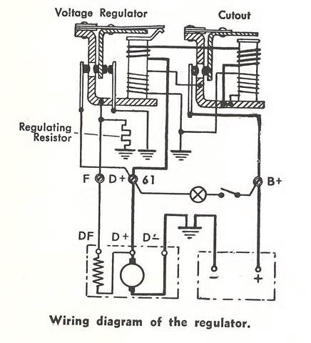
But once the alt is "up" it provides its own current to the field winding (rotor in this case).
Stu,
That is exactly what I am saying. With the alternator at rest Dplus is connected to ground through the windings. If it weren't the positive potential from the battery going through the light and activating the windings wouldn't light up. So the way I described it is that with the key on but engine at rest, the alternator light will glow. They apparently are bootstrapping this connection through the windings to ground to also light the brake light as a test. Then when the alternator spins up, the diode behind the gauges prevents the current from the alternator from getting into the low side of the brake warning system, which would cook the wires real fast.
I appreciate the diagrams. But I rebuilt an alternator last year diodes and all, so although I am an amateur, I know my electrons.
I wish that folks would focus on my real questions: what about the diode to the seat belt warning light? What is the current flow supposed to be like, although what I would love would be a schematic of the seat belt relay, early version. Transistors and all. If I can understand the ecu interior schematics, I should be able to work through the seat belt diagram.
With that said I much appreciate the help. Wish I knew more.
Warren
What you are struggling with is known as a "Diode Wire Or".
You can wire multiple drive sources (upstream of a diode) to a downstream load without the other sources seeing the drive voltage from each other.
You can wire multiple drive sources (upstream of a diode) to a downstream load without the other sources seeing the drive voltage from each other.
Typically called a steering diode where I worked and learned. Maybe others learned other names, but if you were to look up steering diode you would probably see a load ( in your case, a lamp) that can be powered by more than one 12 volt source of power. One source of power also powers something else( another load) before the lamp in the circuit, so a diode is placed in the circuit just before the junction of power to the lamp to ensure no back feeding of power to the other load.
Tom
Tom
QUOTE(stugray @ Aug 22 2015, 05:55 PM)
What you are struggling with is known as a "Diode Wire Or".
You can wire multiple drive sources (upstream of a diode) to a downstream load without the other sources seeing the drive voltage from each other.
Hi Stu et al,
I edited the first page, hoping to help folks with wiring like I have. I think I answered my own question: see page and post #1.
Thanks everyone.
 are you people talking about?

Electronic s#it, Elliot ... way over your head

EDIT:
I'm sorry, Elliot, that was just downright rude of me.
A diode is actually half of a PNP or NPN silicon junction semiconductor device (AKA a transistor) and only allows electrical current to travel in one direction.
Here's Wiki's explanation:
In electronics, a diode is a two-terminal electronic component that conducts primarily in one direction (asymmetric conductance); it has low (ideally zero) resistance to the flow of current in one direction, and high (ideally infinite) resistance in the other. A semiconductor diode, the most common type today, is a crystalline piece of semiconductor material with a p–n junction connected to two electrical terminals.[5] A vacuum tube diode has two electrodes, a plate (anode) and a heated cathode. Semiconductor diodes were the first semiconductor electronic devices.
The discovery of crystals' rectifying abilities was made by German physicist Ferdinand Braun in 1874. ...
I thought you knew all this, didn't you go to high school with this guy?
QUOTE(euro911 @ Sep 8 2015, 08:01 PM)
Electronic s#it, Elliot ... way over your head
I thought you knew all this, didn't you go to high school with this guy?
Any pilot can make a computer from scratch. it's in their training. Didn't you see Jimmie Stewart in Flight of the Phoenix?
As for Elliot's question, it was a good one. I wanted to rewire the instrument cluster for a triple gauge and wanted to know why the diodes were there so I could decide if I need them. Once I finally understood what was going on, I realized I can simplify things as the seat belt switches are gone, and I generally start the car with the hand brake on. So, I don't need those diodes. On some models, starting requires signals from the seat belt system, and I didn't want to mess up starting function.
As it turns out I am pretty sure the starter switch that came on the roller is toast. Ignition on, start no go.
Also while we are thinking of diodes we might consider the Flemming valve vacuum tube...
I wonder if a Russian version of a 914 would have used tubes in the ECU?
Many of our younger members probably have never seen the insides of pre-1950's car radios - full of tubes.
Many of our younger members probably have never seen the insides of pre-1950's car radios - full of tubes.
Pilots know all about electrical s#&t. If you put the switch in the "on" position and nothing comes "on" you write it up in the log book and someone comes out and fixes it.
We know about double posts as well.
Well, isn't that fairly common for people your age ...
Im digging this thread up again...
I also have a 72 wiring harness in my car. I have been chasing an alternator charging problem for while. Im not totally certain if this is the answer, but I think that my alternator is not getting excited by the generator gauge light because my diode has been cut out.
Someone tell me whether Im headed in the right or wrong direction.
I need to know what type of diode I need to acquire and then which direction it will need to be wired in.
Pete
This is a "lo-fi" version of our main content. To view the full version with more information, formatting and images, please click here.