See attached photo, this is my D-Jet bench setup. The black box on the left is an EFI Associates 1400 D-Jet tester (circa 1972) that measures the injection pulse width, simulates the trigger contact points over a range of engine RPM's, and provides reference values for the CHT and air temp sensors, as well as the throttle switch operation. The ECU is an 044 that I've used in the past for all of the oscilloscope traces on my web page, I can access any circuit in the ECU with it. I've got a TPS connected to the harness in the middle of the picture, as you turn it it you can watch the injection pulse width increase, then when you stop, you can see the pulse with relax back down (there's a delayed effect as well as an immediate effect). I have an air temp sensor plugged into the harness, and instead of a CHT, I have a variable resistor (half of a pot) that lets me simulate the engine temperature. That's a NOS 043 MPS in the upper right, with my vacuum pump attached to simulate engine load.
I've also got an interposer box that I can put between the ECU and the wiring harness that can be installed into the car so I can monitor all of the ECU pin connectors while driving the car. My current box is a PITA to use in the car, my old design sucks. I've got an idea for a better one that I'm going to have to build.
I've also got a Fluke calibrated pressure sensor that I can independently monitor the manifold pressure, or the pressure at any other point in the vacuum system. I can datalog the output from my DMM to get any of the pressure values as a function of time.
Now, just gotta do something useful with it all. BTW, working on the 914 is one of about a million things I'm trying to do simultaneously, so I tend to get to it irregularly, just hoping that's more than "never". I plan to look into the hot start problem first. I'm going to take some data when it happens on the car (i.e. measure the voltage at the CHT through the sequence of events), bench simulate it, then try to come up with some simple solutions. The idle stabilizer will take longer to do.
Full Version: D-Jet Bench Setup
Brad, That's an awesome testing setup, and I look forward to whatever you have to share from this. I know me and the other D-Jetters still left around will only benefit.
Glad to see you back here and in the 914 Brad!
Your inquisitive mind will no doubt solve a few mysteries for others. Will send you an email or PM.
Your inquisitive mind will no doubt solve a few mysteries for others. Will send you an email or PM.
Please find an electronic replacement for the MPS so we can start using different camshaft profiles
Nice! That looks a lot like many of my various workbenches I have around here!
You could invest in a USB oscilloscope for under $100 and it would make a great tool for that setup.
Please find an electronic replacement for the MPS so we can start using different camshaft profiles
I have given that some thought and the concept is relatively simple.
Read the Manifold pressure, and simulate the output of the MPS under the same circumstances.
The concept is really simple using a microcontroller to read a MAP sensor, then an analog output to drive the ECU with a waveform that is similar to the original.
The last bit is the hard part.
Simulating the actual response of the MPS accurately is tricky partially because it swings above & below GND, so you need a output op-amp with a +/- DC supply that has the range you need.
Still not that difficult to build.
I have worked through the concept and even have the MAP sensor and postage stamp sized microcontrollers that would work, and a +/-12VDC-DC converter.
If Brad is interested in experimenting, I might pitch in some parts and some code.
You could invest in a USB oscilloscope for under $100 and it would make a great tool for that setup.
QUOTE(r_towle @ Nov 20 2015, 02:10 PM) 
Please find an electronic replacement for the MPS so we can start using different camshaft profiles
I have given that some thought and the concept is relatively simple.
Read the Manifold pressure, and simulate the output of the MPS under the same circumstances.
The concept is really simple using a microcontroller to read a MAP sensor, then an analog output to drive the ECU with a waveform that is similar to the original.
The last bit is the hard part.
Simulating the actual response of the MPS accurately is tricky partially because it swings above & below GND, so you need a output op-amp with a +/- DC supply that has the range you need.
Still not that difficult to build.
I have worked through the concept and even have the MAP sensor and postage stamp sized microcontrollers that would work, and a +/-12VDC-DC converter.
If Brad is interested in experimenting, I might pitch in some parts and some code.
Do it! Get 'er done! Keep the four pole MPS harness connection and location and it will work with existing harnesses, or I will make a new harness design to accommodate.
Digital D-Jet!
Digital D-Jet!
I've posted in the past about the issues with replacing the MPS with a modern electronic pressure sensor, I'll briefly summarize. It wouldn't be a simple task, because the two coils in the MPS are an integral part of the multivibrator circuit in the ECU, and also because the MPS itself is the system element that handles mixture enrichment and transition under full load conditions. Now that rebuild kits are available, it's easier to rebuild an MPS that to build an active microcontroller and sensor system to simulate its operation. If anyone disagrees and wants to prove me wrong, I'll probably the first guy to buy your new replacement system!
QUOTE(stugray @ Nov 20 2015, 05:28 PM)
Nice! That looks a lot like many of my various workbenches I have around here!
You could invest in a USB oscilloscope for under $100 and it would make a great tool for that setup.
You can't see it in the photo, but to the left is a full-on '70's era Tek oscope with storage and 4 channels, as well as a set of plug-ins that include a precision pulse width measurement module. I also have a full electronics lab where I've got a Seeed DSO Nano v3 scope, logic analyzer, bus analyzer, etc., and all the parts and stuff for doing sensor work on Arduino, Raspi, PICAXE, and XBee based systems. I just finished building a XBee sensor network for the house which uses a Raspi for the controller and data aggregation node, it's monitoring for leaks at my water heaters and monitoring motion at my side gates. Sends me a text message if any leaks occur or if the gates are opened, as well as a daily summary. I'm going to be expanding it in the future to monitor more systems, use mysql for storing the sensor data, and providing several ways to alert me and to display the system status on a web page.
So, yeah, I'm into electronics

Small world!
I have an arduino datalogger in the racecar that reads RPM, AFR, EGTs, CHTs, Oil temp, oil press, fuel press, & throttle position.
It logs it to a sdcard at 1Hz and outputs it via USB.
It also controls the shift light & the dash warning light and can be set to alarm on whatever limits I want. (currently just low oil press).
If I plug an android device into it (via USB) while driving, I have an android app that logs it (again) and displays the data on a digital dash (like Torque).
My latest project:
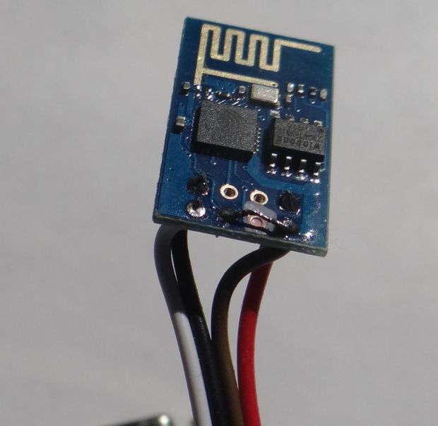
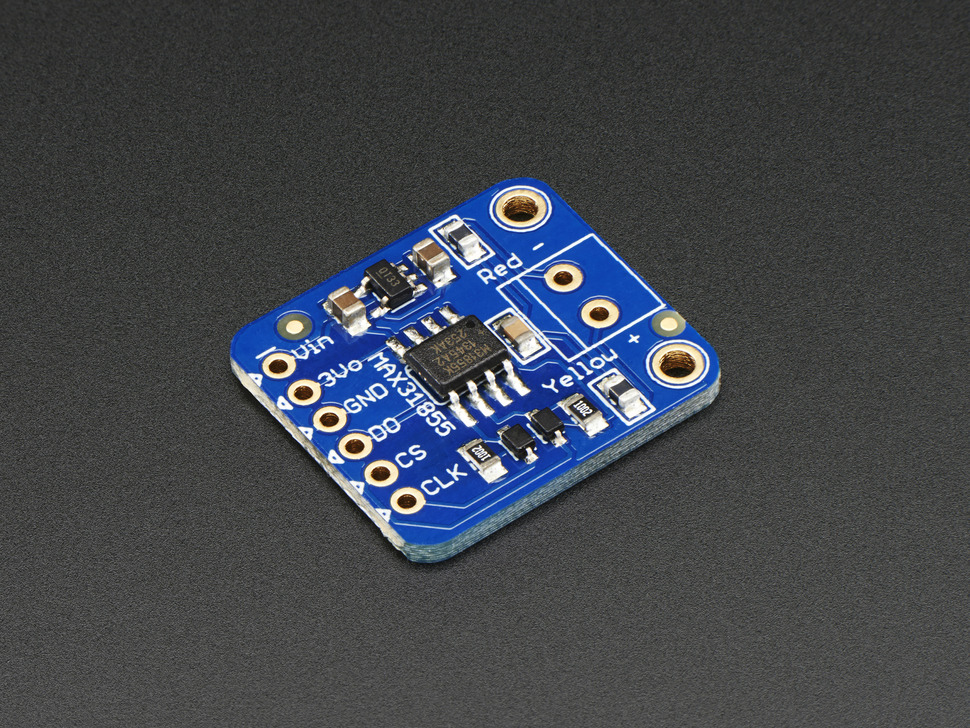
I also just recently got a couple ESP8266 wifi SOCs and have one reading two adafruit Thermocouple amplifiers & broadcasting it via wifi.
I want a thermal logging device that can do 4X thermocouples and 4X non-contact IR temp sensors for various race related troubleshooting.
I know someone that is destroying brakes on his racecar and I want to see if I can help to figure out a solution.
I have an arduino datalogger in the racecar that reads RPM, AFR, EGTs, CHTs, Oil temp, oil press, fuel press, & throttle position.
It logs it to a sdcard at 1Hz and outputs it via USB.
It also controls the shift light & the dash warning light and can be set to alarm on whatever limits I want. (currently just low oil press).
If I plug an android device into it (via USB) while driving, I have an android app that logs it (again) and displays the data on a digital dash (like Torque).
My latest project:
I also just recently got a couple ESP8266 wifi SOCs and have one reading two adafruit Thermocouple amplifiers & broadcasting it via wifi.
I want a thermal logging device that can do 4X thermocouples and 4X non-contact IR temp sensors for various race related troubleshooting.
I know someone that is destroying brakes on his racecar and I want to see if I can help to figure out a solution.
QUOTE(stugray @ Nov 20 2015, 06:39 PM)
Small world!
I have an arduino datalogger in the racecar that reads RPM, AFR, EGTs, CHTs, Oil temp, oil press, fuel press, & throttle position.
It logs it to a sdcard at 1Hz and outputs it via USB.
It also controls the shift light & the dash warning light and can be set to alarm on whatever limits I want. (currently just low oil press).
If I plug an android device into it (via USB) while driving, I have an android app that logs it (again) and displays the data on a digital dash (like Torque).
My latest project:
I also just recently got a couple ESP8266 wifi SOCs and have one reading two adafruit Thermocouple amplifiers & broadcasting it via wifi.
I want a thermal logging device that can do 4X thermocouples and 4X non-contact IR temp sensors for various race related troubleshooting.
I know someone that is destroying brakes on his racecar and I want to see if I can help to figure out a solution.
Nice! I just saw one of the big suppliers has a new thermocouple setup (Sparkfun?), when I see it next time I'll send it to you.
QUOTE(pbanders @ Nov 20 2015, 05:08 PM)
I've posted in the past about the issues with replacing the MPS with a modern electronic pressure sensor...
That's what I've been telling people for years, ever since you explained how the MPS worked. Varying the inductive coupling between two circuits based on the manifold pressure will be a pain. By the time you do all the work to adequately simulate it, you've done as much (or more!!) work than it would take to just go all the way and switch over to Microsquirt.
--DD
QUOTE(Dave_Darling @ Nov 20 2015, 10:10 PM)
ever since you explained how the MPS worked.
--DD
Where?
QUOTE(pbanders @ Nov 20 2015, 06:41 PM)
Nice! I just saw one of the big suppliers has a new thermocouple setup (Sparkfun?), when I see it next time I'll send it to you.
Just looked, meh. It's just a single TC board. If you're looking for a quad it's somewhere else.
QUOTE(Shredhead @ Nov 20 2015, 08:49 PM)
QUOTE(Dave_Darling @ Nov 20 2015, 10:10 PM)
ever since you explained how the MPS worked.
--DD
Where?
http://members.rennlist.com/pbanders
Explanations on both the mechanical and electronic operation of the MPS.
Today's learning: The TPS uses a drag switch to prevent additional injection pulses when the throttle is closing, this is well-known. What I didn't know is that the drag switch has to be enabled when the throttle is closed for the idle switch in the TPS to actually turn on, and permit the idle circuit in the ECU to modify the mixture. Why is this important? It means when you install a new TPS, be careful to open and close the throttle several times when setting the position of the TPS, to make sure the idle switch is engaged when it's fully closed, as any slop at closed throttle might result in the idle switch not being engaged.
Brad - I've been chasing an issue (well, several minor issues) for some time that may be relevant to this: always seemed too rich at idle even with the ECU knob all the way CCW. I had replaced the TPS board several months back and thought maybe I boogered up the arms but they seemed to make proper contact to the traces. Then I thought maybe I didn't calibrate the TPS correctly or that something was wrong with the MPS (like leaking aneroid cells or something).
Can you explain in more detail what to check? Are you saying physically observe the movement of the TPS arms when it's mounted to make sure they're making proper contact during throttle movement?
Can you explain in more detail what to check? Are you saying physically observe the movement of the TPS arms when it's mounted to make sure they're making proper contact during throttle movement?
The best thing to do is to check the "idle" pin and the common ground pin to see if they are connected when your throttle is closed. If so, then the switch is set correctly, or at least correctly enough for this particular purpose.
--DD
--DD
QUOTE(pbanders @ Nov 20 2015, 06:08 PM)
I've posted in the past about the issues with replacing the MPS with a modern electronic pressure sensor, I'll briefly summarize. It wouldn't be a simple task, because the two coils in the MPS are an integral part of the multivibrator circuit in the ECU, and also because the MPS itself is the system element that handles mixture enrichment and transition under full load conditions. Now that rebuild kits are available, it's easier to rebuild an MPS that to build an active microcontroller and sensor system to simulate its operation. If anyone disagrees and wants to prove me wrong, I'll probably the first guy to buy your new replacement system!
I thoroughly read your explanation of how the system works, and I believe trying to simulate the MPS output is overkill.
(posting your very own picture here)
As you explain, the MPS outputs a wave form (SC+IM bias) that 'returns to zero' in some amount of time (based on manifold pressure and temp) and controls the width of the injector pulse.
To trick the system, we don't necessarily need to simulate the MPS output exactly.
All we need to do is detect the beginning of the injection pulse (TL trigger goes low), and swing our simulated SC_IM_bias low (to below the trigger threshold = ~-0.7VDC ).
Then the simulator waits until it wants the injector pulse to end, then swing back to zero.
The fact that the simulated output does not look like the real MPS output is irrelevant.
So all the MPS simulator needs to output is a negative going square pulse that swings to below the trigger threshold, then returns to zero when the injector on duration has been reached.
So the MPS simulator output would just be a inverting opamp with a -1.0 VDC negative rail and a 0VDC positive rail.
You could even drive it with a discrete output and don't need to even mess with an analog signal.
It is entirely possible that I am missing something, but I believe it is that simple.
So the MPS simulator would have an analog input connected to a modern 0-5VDC Manifold pressure sensor, an intake air temp sensor, and an input trigger connected to the MPS input from the ECU.
It would use a lookup table to determine the desired injector pulse width.
When the MPS input pulse is detected, it just drives the MPS output to ~-1.0 VDC and holds it there until the injector pulse duration has been reached then drives the signal back to GND.
(in fact the signal could mimic the waveform in your diagram labeled 'Injection pulse duration')
The ECU will see the signal cross the threshold and end the injector pulse.
Am I close?

QUOTE(pbanders @ Nov 20 2015, 06:41 PM)
Nice! I just saw one of the big suppliers has a new thermocouple setup (Sparkfun?), when I see it next time I'll send it to you.
I am using one of these:(Wifi_SOC)
connected to some of these: (TC_amp)
And then some of these: (IR_temp_sense)
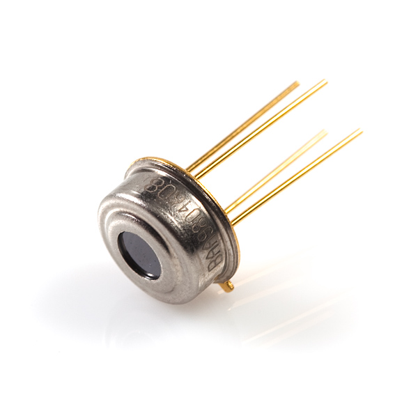
And I will be able to log 4X thermocouples and 4X IR temp sensors all over wifi to a phone.

And I'll make the cables long enough to reach all 4 wheels of a car.
And I know, it's not fair, but I drive by Sparkfun every day on my way to work.....
(I cheat:-)
QUOTE(Dave_Darling @ Nov 21 2015, 01:24 PM)
The best thing to do is to check the "idle" pin and the common ground pin to see if they are connected when your throttle is closed. If so, then the switch is set correctly, or at least correctly enough for this particular purpose.
--DD
Thanks Dave. Spent some time checking this out this morning. As mentioned, I've had a persistent problem of being too rich at idle, and it's hard to tell if the ECU Pot knob is actually doing anything. Based on checking, I don't think I have connectivity between pin 12 and 17 on ECU connector when throttle is closed, and I couldn't find connectivity between the TPS connector (middle wire) and pin 12 on ECU connector.
I assume it should be there. I'll start a new thread...
The wire to the center cavity of the 5-pole TPS connector goes to cavity 11 at the ECU connector.
Cavity 12 at the ECU connector is the center wire at the trigger points
Cavity 12 at the ECU connector is the center wire at the trigger points
That would do it. I'll check again. Thanks Jeff!
QUOTE(stugray @ Nov 21 2015, 12:37 PM)
QUOTE(pbanders @ Nov 20 2015, 06:08 PM)
I've posted in the past about the issues with replacing the MPS with a modern electronic pressure sensor, I'll briefly summarize. It wouldn't be a simple task, because the two coils in the MPS are an integral part of the multivibrator circuit in the ECU, and also because the MPS itself is the system element that handles mixture enrichment and transition under full load conditions. Now that rebuild kits are available, it's easier to rebuild an MPS that to build an active microcontroller and sensor system to simulate its operation. If anyone disagrees and wants to prove me wrong, I'll probably the first guy to buy your new replacement system!
I thoroughly read your explanation of how the system works, and I believe trying to simulate the MPS output is overkill.
(posting your very own picture here)
As you explain, the MPS outputs a wave form (SC+IM bias) that 'returns to zero' in some amount of time (based on manifold pressure and temp) and controls the width of the injector pulse.
To trick the system, we don't necessarily need to simulate the MPS output exactly.
All we need to do is detect the beginning of the injection pulse (TL trigger goes low), and swing our simulated SC_IM_bias low (to below the trigger threshold = ~-0.7VDC ).
Then the simulator waits until it wants the injector pulse to end, then swing back to zero.
The fact that the simulated output does not look like the real MPS output is irrelevant.
So all the MPS simulator needs to output is a negative going square pulse that swings to below the trigger threshold, then returns to zero when the injector on duration has been reached.
So the MPS simulator output would just be a inverting opamp with a -1.0 VDC negative rail and a 0VDC positive rail.
You could even drive it with a discrete output and don't need to even mess with an analog signal.
It is entirely possible that I am missing something, but I believe it is that simple.
So the MPS simulator would have an analog input connected to a modern 0-5VDC Manifold pressure sensor, an intake air temp sensor, and an input trigger connected to the MPS input from the ECU.
It would use a lookup table to determine the desired injector pulse width.
When the MPS input pulse is detected, it just drives the MPS output to ~-1.0 VDC and holds it there until the injector pulse duration has been reached then drives the signal back to GND.
(in fact the signal could mimic the waveform in your diagram labeled 'Injection pulse duration')
The ECU will see the signal cross the threshold and end the injector pulse.
Am I close?
I've thought through the same thing, it should be possible, I lacked the skills to implement, though I've been working on that! I assume the lookup table would encompass the full-load enrichment function, too? If you can mock up a prototype I can test it on my simulator and do a direct comparison to a stock MPS.
stugray, which pressure sensor are you thinking of using? I2C or 1-wire? I could also give your design a try.
Brad,
Did you get my PM from a day or so ago?
Tom
Did you get my PM from a day or so ago?
Tom
QUOTE(pbanders @ Nov 22 2015, 10:30 AM)
I've thought through the same thing, it should be possible, I lacked the skills to implement, though I've been working on that! I assume the lookup table would encompass the full-load enrichment function, too? If you can mock up a prototype I can test it on my simulator and do a direct comparison to a stock MPS.
You could test the theory.
Do you have an arbitrary function generator?
If you can configure it for:
Single pulse, adjustable duration squarewave.
Amplitude 1.0VDC, Offset -1.0VDC
Negative going pulse
External trigger input connected to 'TL Trigger' (input excitation signal into MPS)
Connect waveform output to MPS Output to ECU
Now test the system while varying pulse durations on the arb gen, and you should be able to control the injector pulse duration just like adjusting the vacuum on your MPS vacuum pump
QUOTE(pbanders @ Nov 22 2015, 10:36 AM)
stugray, which pressure sensor are you thinking of using? I2C or 1-wire? I could also give your design a try.
I just grabbed something simple off of ebay that I could actually find the datasheet for (or thought I could...)
I ended up with a Denso TN079800-3280 5V PS-30
I also found a small DC-DC converter from Digikey for the neg DC voltage.
If the experiment above with the -1.0VDC pulse works and we don't need to simulate some funky waveform, then an Op-amp wouldn't be required and we could just use an opto to pull down to the neg DC rail for the output signal.
If you really want to experiment, I could send you the MAP sensor, an arduino beetle, the DC-DC converter, some 1-wire temp sensors, and I even have some high speed optos laying around.
QUOTE(pbanders @ Nov 22 2015, 10:36 AM)
stugray, which pressure sensor are you thinking of using? I2C or 1-wire? I could also give your design a try.
Out riding my bike and thinking - digital pressure sensor probably won't be fast enough, probably have to use an analog automotive sensor and sample it at about a 1 ms rate.
QUOTE(stugray @ Nov 22 2015, 11:22 AM)
QUOTE(pbanders @ Nov 22 2015, 10:30 AM)
I've thought through the same thing, it should be possible, I lacked the skills to implement, though I've been working on that! I assume the lookup table would encompass the full-load enrichment function, too? If you can mock up a prototype I can test it on my simulator and do a direct comparison to a stock MPS.
You could test the theory.
Do you have an arbitrary function generator?
If you can configure it for:
Single pulse, adjustable duration squarewave.
Amplitude 1.0VDC, Offset -1.0VDC
Negative going pulse
External trigger input connected to 'TL Trigger' (input excitation signal into MPS)
Connect waveform output to MPS Output to ECU
Now test the system while varying pulse durations on the arb gen, and you should be able to control the injector pulse duration just like adjusting the vacuum on your MPS vacuum pump
QUOTE(pbanders @ Nov 22 2015, 10:36 AM)
stugray, which pressure sensor are you thinking of using? I2C or 1-wire? I could also give your design a try.
I just grabbed something simple off of ebay that I could actually find the datasheet for (or thought I could...)
I ended up with a Denso TN079800-3280 5V PS-30
I also found a small DC-DC converter from Digikey for the neg DC voltage.
If the experiment above with the -1.0VDC pulse works and we don't need to simulate some funky waveform, then an Op-amp wouldn't be required and we could just use an opto to pull down to the neg DC rail for the output signal.
If you really want to experiment, I could send you the MAP sensor, an arduino beetle, the DC-DC converter, some 1-wire temp sensors, and I even have some high speed optos laying around.
If you send the stuff to me, I can't tell you when I'd get around to it. You'd be better off doing it and I could test it out if you want, unless you have everything you need to verify it. re: Denso sensor - yeah, that's what's needed. As for the proof of concept, I don't have an arbitrary function generator but could probably do a circuit with a 555 or two that could do the function you describe.
What sampling rate does the megasquirt use? I'm figuring this would need to be about on the same order.
QUOTE(Tom @ Nov 22 2015, 10:54 AM)
Brad,
Did you get my PM from a day or so ago?
Tom
Will check, just got back on here today.
QUOTE(pbanders @ Nov 22 2015, 12:24 PM)
Out riding my bike and thinking - digital pressure sensor probably won't be fast enough, probably have to use an analog automotive sensor and sample it at about a 1 ms rate.
I don't think we would need to sample the MPS and the air intake temp that fast, maybe 10 Hz?
Then throw in some digital filtering (average) in software and you would have less than a few tenths of a second latency.
I'd have to play with the MAP and an oscope on a real engine to know how fast it even responds.
You wouldn't even sample the input trigger, it would operate on a input channel event trigger (arduino attachInterrupt()).
So every time the subroutine is called by the input trigger (TL goes low) it:
drives the SC_IM_bias output signal to -1.0V. (or some negative voltage TBD by experiment).
latch a system time (start_of_pulse)
Read the time averaged MAP value (MAP)
Read the time averaged Input temp sensor reading (IAT)
Using those two values, lookup a pulsewidth from a lookup table (pulsew)
set the timer in the future for start_of_pulse + pulsew
exit from interrupt routine
When the timer goes off:
drive signal SC_IM_bias output signal to 0.0V
ECU stops the injector pulse.
This subroutine would run every time the TL input signal goes low
In the "downtime" between the subroutine running, it would collect & average the MAP & Temp sensor data.
QUOTE(pbanders @ Nov 22 2015, 12:29 PM)
If you send the stuff to me, I can't tell you when I'd get around to it. You'd be better off doing it and I could test it out if you want, unless you have everything you need to verify it. re: Denso sensor - yeah, that's what's needed. As for the proof of concept, I don't have an arbitrary function generator but could probably do a circuit with a 555 or two that could do the function you describe.
What sampling rate does the megasquirt use? I'm figuring this would need to be about on the same order.
You absolutely could do this as proof of concept with a 555 in monostable mode.
Hookup a +/-5VDC power supply and use the 555 to drive a opto/mosfet to pull the test signal up & down
QUOTE(pbanders @ Nov 22 2015, 11:30 AM)
QUOTE(Tom @ Nov 22 2015, 10:54 AM)
Brad,
Did you get my PM from a day or so ago?
Tom
Will check, just got back on here today.
Well, as I live and breathe you are one of my heroes! I am still chasing my Raby sort of webcam 73, and your work has been essential to me.
Thanks for all you have done.
stugray, thanks, will let you know when I get to doing the POC. Resurrecting all the stuff I did on this 5-10 years ago is going to take me some time.
This is a "lo-fi" version of our main content. To view the full version with more information, formatting and images, please click here.