EDITED to put smaller pictures below.
Ok, so my sister has a 1971 Porsche 914 that somehow I've been asked to get running again. It's had a few too many people under the hood over the years so there's quite a list of projects to do.
So first question is there a good manual that would be recommended for these so I might not have to ask question like will be below. Haynes, Chilton, ??
One of the first project is new fuel line front to back as they are pretty rotted. Next project is to verify the wiring as there's been a lot of playing around with the double relay.
Since I'm doing fuel lines the tank is out. Under the tank was a vacuum type line that didn't seem to have a home. Any suggestions where this was supposed to go. Come through the floor loops around and ends up by steering shaft.
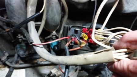
Next question is what are the correct names two sensors? They are part of the double relay wiring and I'm tracing wires. Blue one, Brown one.
And then for now on this thread. What is this?
Full Version: 1971 part identification
Like to help but pictures are so large and blurry??
Reduce the size and they'll probably clear up, or take a few new ones with a smaller resolution.

Reduce the size and they'll probably clear up, or take a few new ones with a smaller resolution.
looks like the brake fluid reservoir over flow line
found a picture
Click to view attachment
Click to view attachment
Not sure why the pics are so large. I even compressed them and resized them. I'll work on that.
Use the post preview to see how your photos will look on the screen.
OK not sure why they wouldn't come across smaller. Maybe cached somewhere? I renamed each one that I compressed and resized and it seems to have worked..
What's this?
What are the names of these sensors?
And as above this may be the tube to the brake overflow. I'll check tomorrow.
What's this?
What are the names of these sensors?
And as above this may be the tube to the brake overflow. I'll check tomorrow.
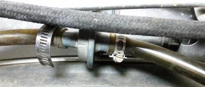
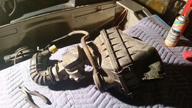
First picture is a late AAR, usually found on L-Jet 1.8 engines.
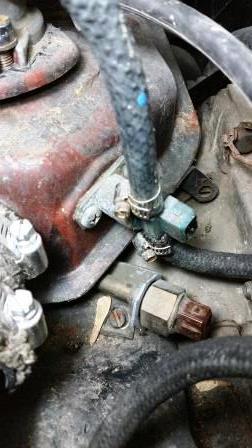
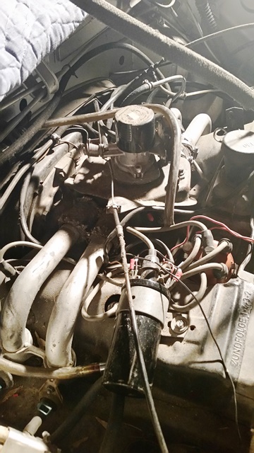
The second picture shows the cold start valve on the plenum, and the thermostatic switch down below. The thermostatic switch is what 'turns on' the cold start valve when it's cold.
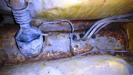
The last pic looks more like the gas tank breather hose. The brake res. overflow looks like it goes out next to the other brake lines there.
The second picture shows the cold start valve on the plenum, and the thermostatic switch down below. The thermostatic switch is what 'turns on' the cold start valve when it's cold.
The last pic looks more like the gas tank breather hose. The brake res. overflow looks like it goes out next to the other brake lines there.
Haynes for the manual. It's not very good, but there isn't really anything better--except this forum!! Pelican has some pretty good Tech Articles, and there are other good sites like Jeff Bowlsby's "914 Tech" pages and such. But for a paper manual, Haynes is it. It has about 85% of the information from the $300+ factory manuals. As in, words and pictures lifted directly from the factory manuals.
Sounds like you have a 1.8 liter engine (and FI system) from a 74 or 75 transplanted into that 71. (Double-check the VIN; if it starts with 471 it is a 71, if it starts with 475 it's a 75.) The year will matter for things like the wiring.
Short descriptions of the AAR and CSV:
- The AAR allows some air that has been measured by the air-flow meter to bypass the throttle valve. It raises the idle RPM when the engine is cold. It should have an electrical plug that powers a little heating element inside it, so that after 5-10 minutes of the engine running the valve is closed. When the valve is cold, it should allow air to go through it; when the valve is warm it should not.
- The CSV adds an extra spray of fuel into the intake manifold while the starter is cranking, if the engine is cold enough. It gets its power from the starter circuit, and is grounded through a switch that is closed when below 40F (or maybe 32F). This is to help a very cold engine to light off and start running. Once the starter is no longer cranking, the CSV will no longer spray fuel.
L-jet hates vacuum leaks; triple-check everything downstream of the air flow meter for leaks. Note that the crankcase gets plumbed into the intake, so the oil filler needs to make a good seal as well!
--DD
Thanks for the replies this will help.
Any other ways to determine if this is a transplant? VIN is 471. It's air cleaner is one that takes a square filter like the current newer model cars of today. This is also one that was made into a convertible so it's had a few mods over the years.
I've found both Pelican and Bowlsby's sites and been wearing them out from all my traffic. My experience is 8 cylinders and carbs so this is a new adventure for me.
Yes the AAR valve had an electrical plug from the FI harness. In my pics the harness is on my bench as I've been pinning it out trying to determine if the double relay is wired correct. Needless to say it's wiring condition showed that it had been messed with quite a bit.
Last known status of the car was that it would start and then die once the key was released. This was back in 2012. So I figured I'd start by making sure this relay was wired properly.
But in reviewing other items I found all the fuel lines rotted and somewhere there is no longer a fuel filter so that is my current project. Surprisingly the tank only had a few signs of light rust inside and looked pretty clean.
Then I'll get to tackle the shifter system. There is no rear bushing and the rod has popped out of the transmission part.
And on and on and on......
I put a couple more photos up. So here it is at its arrival at my place.
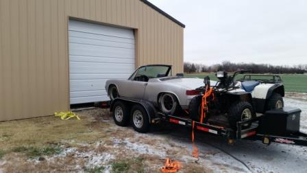
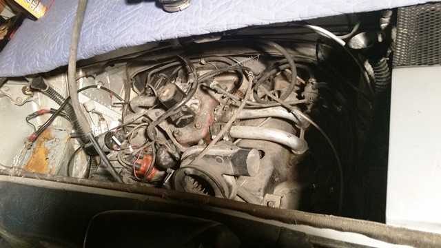
And here is the joy I found under the hood.
Any other ways to determine if this is a transplant? VIN is 471. It's air cleaner is one that takes a square filter like the current newer model cars of today. This is also one that was made into a convertible so it's had a few mods over the years.
I've found both Pelican and Bowlsby's sites and been wearing them out from all my traffic. My experience is 8 cylinders and carbs so this is a new adventure for me.
Yes the AAR valve had an electrical plug from the FI harness. In my pics the harness is on my bench as I've been pinning it out trying to determine if the double relay is wired correct. Needless to say it's wiring condition showed that it had been messed with quite a bit.
Last known status of the car was that it would start and then die once the key was released. This was back in 2012. So I figured I'd start by making sure this relay was wired properly.
But in reviewing other items I found all the fuel lines rotted and somewhere there is no longer a fuel filter so that is my current project. Surprisingly the tank only had a few signs of light rust inside and looked pretty clean.
Then I'll get to tackle the shifter system. There is no rear bushing and the rod has popped out of the transmission part.
And on and on and on......
I put a couple more photos up. So here it is at its arrival at my place.
And here is the joy I found under the hood.
Double relay means it's using L-jetronic injection, which would indicate a 1.8 L engine. Engine code would start with "EC" on an original 1.8 engine; check on the right-rear section of the top of the case.
The 71s were either available with a 1.7 liter four-banger with D-jetronic EFI, or a 2.0 liter six cylinder with carbs. L-jet is a transplant. In fact, the very first production L-jet car ever was the 74 1.8 liter 914.
--DD
The 71s were either available with a 1.7 liter four-banger with D-jetronic EFI, or a 2.0 liter six cylinder with carbs. L-jet is a transplant. In fact, the very first production L-jet car ever was the 74 1.8 liter 914.
--DD
Ok so confirmed loose line in front should go to brake overflow.
On the engine I found a stamped number just right of centerline behind the intake. Code was W0122384. Is that my engine code? What does it means? And sounds like I may have a Frankenstein if it's an early engine with later injection.
On the engine I found a stamped number just right of centerline behind the intake. Code was W0122384. Is that my engine code? What does it means? And sounds like I may have a Frankenstein if it's an early engine with later injection.
W is the code for an early 1.7 engine. It could be the original engine block for that car, in fact.
It is relatively easy to change around parts on these engines, so it is possible that you have a 1.8 built on the 1.7 case (or a 2.0, even) with the L-jet. Difficult to know the exact displacement without taking the motor apart, though. It's probably safest to treat this as a 1.7 with the 1.8's L-jet installed on it.
--DD
From the look of the plenum and throttle body, I would suspect someone transplanted a 912E FI on to the motor.
Great replies and thanks. Any leads I can get to determine what I have will likely help me when I get to the real debugging of this car. Here's some engine bay shots for any further tips or ideas on what I might have.
Wow, Clay--you could see the photos before he posted them?
Yes, that looks like a 912E setup. The 912E had what was (more or less) a 75-76 2.0 liter 914 motor, with a unique L-jet setup. The manifold and throttle body are very similar to the 2.0 914's D-jet manifold and throttle body, for instance.
The spark plug holes say that you don't have 2.0 liter heads. That doesn't mean the displacement is necessarily 1.7 liters, though. It does seem odd that they put a 912E setup on, or at least part of a 912E setup, on a stock 1.7 motor. No idea what to say about that.
Interesting setup, that. You may wind up needing to write down part numbers of all of the parts you have in order to figure out exactly what was used.
--DD
Great thought on recording the part numbers. Since its all apart its a good time.
So maybe this will help the wiring mystery. The fuel pump is currently wired from a harness that runs along the wall in front of the engine, from the relay panel. When I was under the car I thought it might of been a previous attempt at making it run by bypassing the relay, but then I saw it went into what looked like a factory harness on top. I've not worked on tracing those yet, but it certainly wasn't hooked to the dual relay.
So was the 1971 FI fuel pump originally powered differently?
I'm guessing if I get the dual relay worked out and this seems to be newer FI that it would be best to power the fuel pump from the relay.
The 71 would be D-jet. D-jet runs its pump off a relay in the relay board on the left side of the engine bay. The 74 1.8 fed that same circuit in the relay board, but without going through the relay. The output from the dual relay went into one pin of the 12-pin relay at the rear of the board. Inside the board, it connected through to a different pin of the 12-pin connector, and then went to the pump.
I'm less sure of how the 75 1.8 handled it, but I suspect something similar happened, possibly with the output wire being in the main wiring harness (the 14-pin connector at the front of the relay board) instead of the FI harness.
The same relay board was used for all years and fuel injection types. (Exception: The 914-6 used a different board.)
--DD
This is a "lo-fi" version of our main content. To view the full version with more information, formatting and images, please click here.