Help - Search - Members - Calendar
Full Version: I'm building a rotisserie with a difference
914World.com > The 914 Forums > 914World Garage
andrewb
I'm building a rotisserie with a difference - I'd be interested in what you experts think.

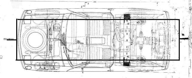
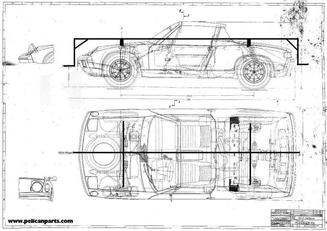
This is a rough schematic of how it's going to work.

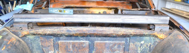
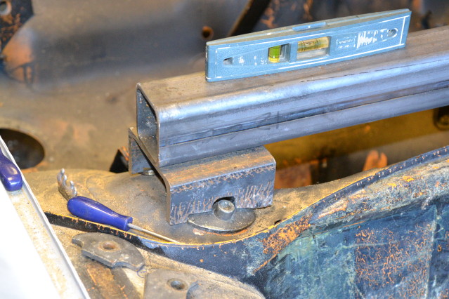
The main spine and the cross members are 60mm steel box section.

The short stubs at either end will then connect to conventional 'engine stand' type stands.

IPB Image


I've never liked the idea of picking a car up the conventional way, by it's extremities, as it means putting loads into the car in directions it wasn't designed for - and besides 2 of my bumper mounts are rotten and one has crash damage - and is rotten.

My next thought was to fix the spit to the suspension mounts underneath which is another common way of doing it but this would be difficult to measure and fabricate - working upside down - and besides there's work to be done on the suspension mounts as well !

So finally I hit on the idea of mounting off the top of the shock towers - easy access, the loads will be in more or less the right direction and it will be very easy to build something with the minimum of fancy fabrication. A bonus is that the whole structure will act as a brace although I have got door braces fitted as well. The biggest plus is that the whole of the underside is completely open and easy to get at.

At the moment I'm just finishing off the front crossmember which will be welded to the clamping plates which normally hold the tops of the shocks.

IPB Image

IPB Image

Has anyone done anything like this before ?
URY914
Go for it! beer.gif
maf914
Interesting arrangement and I hope it works. I am not a structural engineer, and don't mean to be pain-in-the-a##, but I see a couple of issues.

I wonder where the center of gravity is in the longitudinal plane? Where should the pivots be located vertically? At bumper height or a bit higher?

As drawn, is the single longitudinal support beam, with the offsets at the front and rear, strong enough to support the weight as the car is rotated? It looks like there might be some weird torque forces on this.
McMark
agree.gif When turned 90-degrees, you're center spine is going to be twisting under the weight of the car. I hope you really trust your welding skills.
bandjoey
I'm no engineer of anything. With a conventional setup at 90' or any position all the weight is straight down on the round pivot. Side stress is transferred to the floor base. Size of steel and braces at the floor are stressed but not so much the car.

This new idea seems to be ok on the car but the "L" drop at each end is the twisting point. So. Here's where Size of steel and bracing has to take place. I'm sure this has been taken into account. And welding skills.

Will enjoy watching. You might be onto something totall new. welder.gif
toolguy
It will be in the way when you paint.

Center of gravity is close to center of bumpers on the ones I've built.

The main stress on your design will be on the "L" ends up to where thay are welded
on the cross bars. . If it were me and you proceed, use gussets at all welds. <And thick wall tube>
PanelBilly
I think you need to add a beam from end to end at the ground level. Make it removable.
andrewb
Cheers gents, some useful thoughts there some of which I think I've catered for, others maybe not.

The main concern seems to be around the twisting moment on the central spine when the car is at 90 degrees. Perhaps I've not thought about this enough although I should show you how I intend to connect the spine to the cross members.

IPB Image

I may use diagonal braces or water jet cut steel plate triangles. Whether this sufficiently addresses the twist issue depends on how I arrange the steelwork where it meets the spine. I do have Solidworks which includes a stress analysis package and I will be running the design through that. (Need to keep an eye on the weight or it will weigh more than the car biggrin.gif ) The shell will be about 520 lbs by the way.

I may go back to an earlier design which was to have two longitudinal pieces although still mounted to the top of the shock towers, something like this.

IPB Image

I can still go this route - the cross members between the towers (not shown on this sketch) will be the same either way. I should have added some bracing/gussets where the rails join and go to the pivot.

Other points:

Do I trust my welding ? No not yet so I'll prep and tack it and then the welding will be done by a friend who makes large steel fabrications professionally.

The CG is somewhere around bumperline - adjustment will be designed in so as to get it spot on and to move it as steel replaces rust.

Steel thickness - I'm using 60x60mm box with a wall thickness of 3mm for the short sections and 5mm for the long ones. Total weight may become an issue.

A beam underneath - yes I'll be fitting something (probably only 40mm box) joining the 2 stands together. For safety and to keep the pivots aligned.

And finally Toolguy, a very good point which I had not considered at all - but even in my dreams I don't think about paint - it's too far off biggrin.gif Seriously though I think I could paint the underside, fit the running gear, roll it over and drop it on its wheels and then paint the top.

The more I think about the twist on the spine the more I think you guys are right. I'll carry on with the cross members and work on CADding the connection to the spine but there's a good chance I'll go the twin longitudinal route. What are your opinions on that ?

Thanks again,
Andrew.
This is a "lo-fi" version of our main content. To view the full version with more information, formatting and images, please click here.
Invision Power Board © 2001-2024 Invision Power Services, Inc.