Can anyone divulge details on the Renegade Hybrid radiator system such as dimensions, Inlet and outlet sizes and rad type (number of rows, if cross flow etc...). Is it even allowed ;-)?
This hot summer has proven that my system cannot handle it. I have some good components such as a 2000 cfm, 9 blade fan out of a Ford Taurus. The remote mechanical water pump is a standard R.H. unit. I also have a Griffin radiator, model 125241-H... no radiator cap (inlet=1.5" and outlet=1.75").
https://www.summitracing.com/parts/gri-1-25241-x
The dimensions are 16"x 27.5" x 3". it is a 2 row unit. Although the inlet/outlet sizes are different, the hoses carrying coolant from front to rear are all the same size at 1.25 inch diameter. The Tech rep at Griffin seems to think that the rad should be fine but I ain't no 4 core unit either.
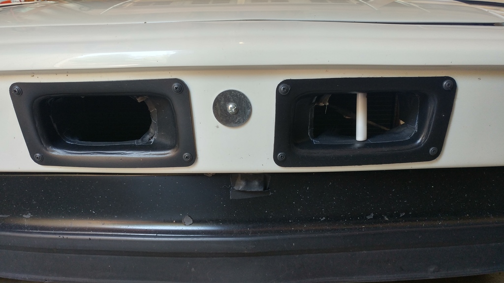
The other part of this is the car has a Chalon kit installed. I question whether the bumper opening for rad air is sufficiently sized. The opening is ducted to the bulkhead opening. The inner fender walls are fully open to allow the air to exit.
From all that I've read; the viable solutions is to either go with a RH rad setup (or as close to as possible) and/or go with an electric water pump. I think I have some (most) of what RH would sell me as there rad kit. The only difference I can see is the rad size/type and the bumper opening size.
Pictures of my current setup can be found here:
http://www.914world.com/bbs2/index.php?sho...132273&hl=#
I feel like I am close to getting this figured out. Just a bit more tinkering is needed.
Thanks!
Full Version: Hot Summer; Hot, Overheating V-8 Radiator Setup.
Your radiator should be big enough. Mechanical pump? Like a stock chevy pump? Might be a flow problem. The outlet holes should be double the inlet hole for best low pressure behind the radiator.
You can only have a few problems...
Poor water flow
Air pocket in the system (very common)
Poor air flow through the radiator
That's it.
My AFCO radiator was the same size when I ran a V8. The key was to ensure there was no possible path of air around the radiator. None.
I would also use a vacuum pump through a holding tank to pull a vac on the system at the high point. At the low point I would have a tank of water with a ball valve closed. Once full vacuum was pulled, I would open the ball valve to suck in water. close the valve and do it again and again until no air came through the holding tank.
I now run a Celica GTS radiator and it fits way better and has absolutely ZERO possible air flow around it. Engine never, ever gets above about 180F. Even if I leave it idling on a hot summer day.
link doesnt go to build thread
Interesting. What year GTS? Did you pick it up at a dismantler? How much?
I Don't think I have any air pockets but I am not 100% sure. If I can rig something up like you describe, I will try it.
I forgot to add... I recently purchased a couple of 12 inch AC condenser fans off of a 90's Toyota 4Runner. So far I attached them to the inner fender walls to help exhaust the hot air from the radiator and main fan. No difference really. Any other suggestions to place the fan(s)... perhaps as a pusher on the front side of the rad or as a puller on the back side of the bumper grill opening? How about the engine bay area?
Your radiator should be big enough. Mechanical pump? Like a stock chevy pump? Might be a flow problem. The outlet holes should be double the inlet hole for best low pressure behind the radiator.
You can only have a few problems...
Poor water flow
Air pocket in the system (very common)
Poor air flow through the radiator
That's it.
My AFCO radiator was the same size when I ran a V8. The key was to ensure there was no possible path of air around the radiator. None.
I would also use a vacuum pump through a holding tank to pull a vac on the system at the high point. At the low point I would have a tank of water with a ball valve closed. Once full vacuum was pulled, I would open the ball valve to suck in water. close the valve and do it again and again until no air came through the holding tank.
I now run a Celica GTS radiator and it fits way better and has absolutely ZERO possible air flow around it. Engine never, ever gets above about 180F. Even if I leave it idling on a hot summer day.
I Don't think I have any air pockets but I am not 100% sure. If I can rig something up like you describe, I will try it.
I forgot to add... I recently purchased a couple of 12 inch AC condenser fans off of a 90's Toyota 4Runner. So far I attached them to the inner fender walls to help exhaust the hot air from the radiator and main fan. No difference really. Any other suggestions to place the fan(s)... perhaps as a pusher on the front side of the rad or as a puller on the back side of the bumper grill opening? How about the engine bay area?
QUOTE(Mike Bellis @ Jul 26 2016, 09:21 PM) 
Your radiator should be big enough. Mechanical pump? Like a stock chevy pump? Might be a flow problem. The outlet holes should be double the inlet hole for best low pressure behind the radiator.
You can only have a few problems...
Poor water flow
Air pocket in the system (very common)
Poor air flow through the radiator
That's it.
My AFCO radiator was the same size when I ran a V8. The key was to ensure there was no possible path of air around the radiator. None.
I would also use a vacuum pump through a holding tank to pull a vac on the system at the high point. At the low point I would have a tank of water with a ball valve closed. Once full vacuum was pulled, I would open the ball valve to suck in water. close the valve and do it again and again until no air came through the holding tank.
I now run a Celica GTS radiator and it fits way better and has absolutely ZERO possible air flow around it. Engine never, ever gets above about 180F. Even if I leave it idling on a hot summer day.
the pictures of your set up show that there is unsealed areas around the radiator to the front of the air inlet. you have to have that air tight to keep the air flow from going around the radiator. http://www.914world.com/bbs2/index.php?act...t&id=264162 http://www.914world.com/bbs2/uploads/post-...85753_thumb.jpg this is a sealed inlet.
Mine is an ebay special http://www.ebay.com/itm/2-ROW-DUAL-CORE-BO...rVe&vxp=mtr
I am running a factory style dual fan setup.
http://www.ebay.com/itm/2000-2005-TOYOTA-C...Kds&vxp=mtr
for vacuum I use a harbor freight vac pump to a modified 5 gallon air tank. I use claer hos so I can see the liquid. Hos in top of tank to vac pump. hos in bottom of tank to car. I also setup a manometer on the side of the tank so I can see how much liquid is in the tank. I think I have about $150 into the setup.
Thanks for the info. Out of curiosity, what are the dimensions of your bumper grill opening?
Mine is an ebay special http://www.ebay.com/itm/2-ROW-DUAL-CORE-BO...rVe&vxp=mtr
I am running a factory style dual fan setup.
http://www.ebay.com/itm/2000-2005-TOYOTA-C...Kds&vxp=mtr
for vacuum I use a harbor freight vac pump to a modified 5 gallon air tank. I use claer hos so I can see the liquid. Hos in top of tank to vac pump. hos in bottom of tank to car. I also setup a manometer on the side of the tank so I can see how much liquid is in the tank. I think I have about $150 into the setup.
QUOTE(Mike Bellis @ Jul 26 2016, 10:00 PM)
Mine is an ebay special http://www.ebay.com/itm/2-ROW-DUAL-CORE-BO...rVe&vxp=mtr
I am running a factory style dual fan setup.
http://www.ebay.com/itm/2000-2005-TOYOTA-C...Kds&vxp=mtr
for vacuum I use a harbor freight vac pump to a modified 5 gallon air tank. I use claer hos so I can see the liquid. Hos in top of tank to vac pump. hos in bottom of tank to car. I also setup a manometer on the side of the tank so I can see how much liquid is in the tank. I think I have about $150 into the setup.
QUOTE(BRAVE_HELIOS @ Jul 26 2016, 09:03 PM)
Thanks for the info. Out of curiosity, what are the dimensions of your bumper grill opening?
QUOTE(Mike Bellis @ Jul 26 2016, 10:00 PM)
Mine is an ebay special http://www.ebay.com/itm/2-ROW-DUAL-CORE-BO...rVe&vxp=mtr
I am running a factory style dual fan setup.
http://www.ebay.com/itm/2000-2005-TOYOTA-C...Kds&vxp=mtr
for vacuum I use a harbor freight vac pump to a modified 5 gallon air tank. I use claer hos so I can see the liquid. Hos in top of tank to vac pump. hos in bottom of tank to car. I also setup a manometer on the side of the tank so I can see how much liquid is in the tank. I think I have about $150 into the setup.
The width is a standard GT opening but I raised the opening 2" to match the dimensions of my oil cooler.
Yes, but since those pictures were taken, I added foam around the perimeter of the radiator blocking any air from circulating around it.
the pictures of your set up show that there is unsealed areas around the radiator to the front of the air inlet. you have to have that air tight to keep the air flow from going around the radiator. http://www.914world.com/bbs2/index.php?act...t&id=264162 http://www.914world.com/bbs2/uploads/post-...85753_thumb.jpg this is a sealed inlet.
QUOTE(messix @ Jul 26 2016, 09:54 PM)
the pictures of your set up show that there is unsealed areas around the radiator to the front of the air inlet. you have to have that air tight to keep the air flow from going around the radiator. http://www.914world.com/bbs2/index.php?act...t&id=264162 http://www.914world.com/bbs2/uploads/post-...85753_thumb.jpg this is a sealed inlet.
What pressure is your cap?
Do you run a water wetter?
Does it overheat when the car is moving?
Do you run a water wetter?
Does it overheat when the car is moving?
Not sure what a wetter is. Coolant additive? Yes.
Rad cap pressure... I believe 15-16 psi.
Generally speaking; the faster I go (even at constant velocity) the whotter it gets.
What pressure is your cap?
Do you run a water wetter?
Does it overheat when the car is moving?
Rad cap pressure... I believe 15-16 psi.
Generally speaking; the faster I go (even at constant velocity) the whotter it gets.
QUOTE(Mike Bellis @ Jul 26 2016, 10:09 PM)
What pressure is your cap?
Do you run a water wetter?
Does it overheat when the car is moving?
QUOTE(BRAVE_HELIOS @ Jul 26 2016, 09:16 PM)
Not sure what a wetter is. Coolant additive? Yes.
Rad cap pressure... I believe 15-16 psi.
Generally speaking; the faster I go (even at constant velocity) the whotter it gets.
QUOTE(Mike Bellis @ Jul 26 2016, 10:09 PM)
What pressure is your cap?
Do you run a water wetter?
Does it overheat when the car is moving?
I'm thinking you have a water flow problem. Time for an electric pump. Even if you have bad air flow, it should run cooler while moving if your water flow is good.
QUOTE(BRAVE_HELIOS @ Jul 26 2016, 07:35 PM)
Can anyone divulge details on the Renegade Hybrid radiator system such as dimensions, Inlet and outlet sizes and rad type (number of rows, if cross flow etc...). Is it even allowed ;-)?
This hot summer has proven that my system cannot handle it. I have some good components such as a 2000 cfm, 9 blade fan out of a Ford Taurus. The remote mechanical water pump is a standard R.H. unit. I also have a Griffin radiator, model 125241-H... no radiator cap (inlet=1.5" and outlet=1.75").
https://www.summitracing.com/parts/gri-1-25241-x
The dimensions are 16"x 27.5" x 3". it is a 2 row unit. Although the inlet/outlet sizes are different, the hoses carrying coolant from front to rear are all the same size at 1.25 inch diameter. The Tech rep at Griffin seems to think that the rad should be fine but I ain't no 4 core unit either.
The other part of this is the car has a Chalon kit installed. I question whether the bumper opening for rad air is sufficiently sized. The opening is ducted to the bulkhead opening. The inner fender walls are fully open to allow the air to exit.
From all that I've read; the viable solutions is to either go with a RH rad setup (or as close to as possible) and/or go with an electric water pump. I think I have some (most) of what RH would sell me as there rad kit. The only difference I can see is the rad size/type and the bumper opening size.
Pictures of my current setup can be found here:
http://www.914world.com/bbs2/index.php?sho...132273&hl=#
I feel like I am close to getting this figured out. Just a bit more tinkering is needed.
Thanks!
Man I went through the same thing with my old small block 914 tried regular water pump, different size hose lines and four different radiators finally I bit the bullet and purchased The Renegade set up with a 55 gallon Meizere water pump which I mounted close to the radiator and the car stayed between 160 and 190 all day long hot or cold days. Another biggie is to have your system where your air gets bled out and fluid is sucked in. The Renegade set up is a little pricey but it's proven especially with them being in Las Vegas and pay the man one time and be done with it. Then you can focus on a turbo set up. LOL
![popcorn[1].gif](http://www.914world.com/bbs2/style_emoticons/default/popcorn[1].gif)
A restrictive cooling system will overheat,in spite of good airflow.Testing the pump's capacity,against a simulated restrictor,will give the actual numbers.
Air entrapment is the usual suspect,or culprit,another is the pump's rpm.A simple change to a smaller diameter pulley may be sufficient.
A serpentine path of coolant hoses,with high points,will trap air,and restrict flow.
A remote expansion and overflow tank is needed at both ends in the typical installation for that reason.
The low point in the system should be at the center of the wheelbase,both ends rising steadily from there to opposite ends.
The inclusion of two tanks is to allow the waterborne steam bubbles to escape the system at each end.
"Rob Kozak: In your case you can run it any way you want. I run Hilborn on my MG with a Hilborn front cover and cam driven fuel pump. We run a Jabsco "water puppy" boat 12volt water pump plumbed into theports where the original SBC water pump bolted Jegs and Summit both have fittings that bolt on and take AN fittings. The return comes out of the Hilborn manifold and goes back to the radiator. BUT this year Hilborn had port in the back of the manifold and I utilized them by making a cross over hose. I don't know if its any more efficient but it does work as far as flowing is concerned."
http://www.jalopyjournal.com/forum/threads...diagram.464209/
http://www.superchevy.com/how-to/148-0504-...ng-system-info/
http://www.edelbrock.com/automotive/mc/water-pumps/
http://www.chevyhardcore.com/tech-stories/...ic-water-pumps/
http://www.superchevy.com/how-to/engines-d...in/0408sc-pump/

Go with the flow.The photos clearly show the hoses as much larger than 1-1/2",to allow the unimpeded flow of glycol/water mix.

/
Air entrapment is the usual suspect,or culprit,another is the pump's rpm.A simple change to a smaller diameter pulley may be sufficient.
A serpentine path of coolant hoses,with high points,will trap air,and restrict flow.
A remote expansion and overflow tank is needed at both ends in the typical installation for that reason.
The low point in the system should be at the center of the wheelbase,both ends rising steadily from there to opposite ends.
The inclusion of two tanks is to allow the waterborne steam bubbles to escape the system at each end.
"Rob Kozak: In your case you can run it any way you want. I run Hilborn on my MG with a Hilborn front cover and cam driven fuel pump. We run a Jabsco "water puppy" boat 12volt water pump plumbed into theports where the original SBC water pump bolted Jegs and Summit both have fittings that bolt on and take AN fittings. The return comes out of the Hilborn manifold and goes back to the radiator. BUT this year Hilborn had port in the back of the manifold and I utilized them by making a cross over hose. I don't know if its any more efficient but it does work as far as flowing is concerned."
http://www.jalopyjournal.com/forum/threads...diagram.464209/
http://www.superchevy.com/how-to/148-0504-...ng-system-info/
http://www.edelbrock.com/automotive/mc/water-pumps/
http://www.chevyhardcore.com/tech-stories/...ic-water-pumps/
http://www.superchevy.com/how-to/engines-d...in/0408sc-pump/
Go with the flow.The photos clearly show the hoses as much larger than 1-1/2",to allow the unimpeded flow of glycol/water mix.
/
Post pics of the whole system please.
QUOTE(BRAVE_HELIOS @ Jul 26 2016, 09:06 PM)
Yes, but since those pictures were taken, I added foam around the perimeter of the radiator blocking any air from circulating around it.
QUOTE(messix @ Jul 26 2016, 09:54 PM)
the pictures of your set up show that there is unsealed areas around the radiator to the front of the air inlet. you have to have that air tight to keep the air flow from going around the radiator. http://www.914world.com/bbs2/index.php?act...t&id=264162 http://www.914world.com/bbs2/uploads/post-...85753_thumb.jpg this is a sealed inlet.
That's good but how are you sealing off the top. It needs to be a true, closed plenum. +1 on the Celica set up!

Make sure your fill is higher than your radiator and its inline in the system and the air should come out and your overflow tank should replace with fresh coolant. Do you have a bleed anywhere else also.
Heres my in and out on renegade set up.96 deg I run 200 to 225ish.
That's a lighter for ref.
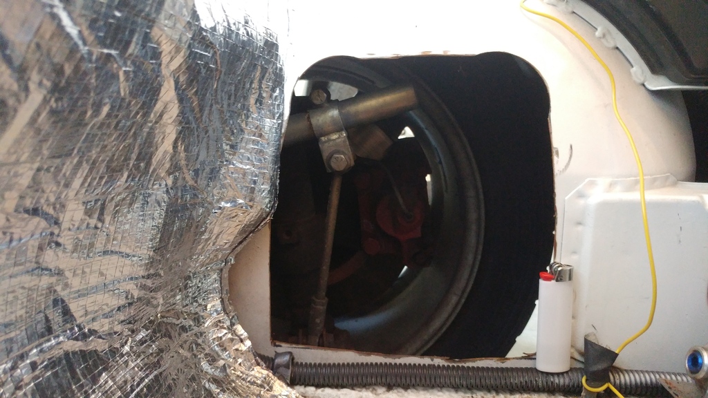
5.3 Ls electric water pump.
That's a lighter for ref.
5.3 Ls electric water pump.
If after you've done all of Mike's suggestions for air flow and removing trapped air then its time for a Davies Craig EWP and LCD controller.
Nothing but good things to say about mine. Granted Im only doing my 1.8T but the system was designed for v8's. Worst case scenario you can use it as an auxiliary flow pump, use the LCD controller to control it and your electric fan.
http://daviescraig.com.au/product/ewp150-a...2v-part-no-8870
This is where I got mine.
http://www.ebay.com/itm/2-Yr-Wy-ALLOY-ELEC...G6w&vxp=mtr
QUOTE(1stworks @ Jul 27 2016, 08:43 AM)
Heres my in and out on renegade set up.96 deg I run 200 to 225ish.
That's a lighter for ref.
5.3 Ls electric water pump.
LS run hotter than old school small blocks. 210-220 normal.
Here are some pictures I took today.
The holes in the shroud are new... as a test top see if it made a difference. I think it did because in the past (with no holey shroud), it did not matter how cold it was outside; the temp would always go to 200 and beyond (have a 160 t-stat with bleed holes drilled and the fan is set to turn on at 180). After cutting the holes in the shroud, the temp would stay at around 180 (acceptable) although it was when it was cooler outside. Now in this 100 degree weather... it does not matter... it still get to 200 and beyond).
The extra fans are from a Toyota 4-Runner AC condenser units and were mounted there temporarily to see if they made any difference in assisting the main fan exhaust air from the front area (they were wired to push air out). They did not work.
What if I could place the radiator more vertically to allow a larger area in front of it (then shroud it too). Would that help any?
Also; my temp sensor is mounted in a port right next to the t-stat/intake manifold.
Post pics of the whole system please.
The holes in the shroud are new... as a test top see if it made a difference. I think it did because in the past (with no holey shroud), it did not matter how cold it was outside; the temp would always go to 200 and beyond (have a 160 t-stat with bleed holes drilled and the fan is set to turn on at 180). After cutting the holes in the shroud, the temp would stay at around 180 (acceptable) although it was when it was cooler outside. Now in this 100 degree weather... it does not matter... it still get to 200 and beyond).
The extra fans are from a Toyota 4-Runner AC condenser units and were mounted there temporarily to see if they made any difference in assisting the main fan exhaust air from the front area (they were wired to push air out). They did not work.
What if I could place the radiator more vertically to allow a larger area in front of it (then shroud it too). Would that help any?
Also; my temp sensor is mounted in a port right next to the t-stat/intake manifold.
QUOTE(Chris914n6 @ Jul 27 2016, 01:35 AM)
Post pics of the whole system please.
Throw that inline filler neck away that,s your problem. Way too hard to get all the air out of the system. Your trying to add water on the high pressure hose. Get a header tank and plump it up like the attached picture .
Click to view attachment
Click to view attachment
QUOTE(BIGKAT_83 @ Jul 27 2016, 03:49 PM)
Throw that inline filler neck away that,s your problem. Way too hard to get all the air out of the system. Your trying to add water on the high pressure hose. Get a header tank and plump it up like the attached picture .
Click to view attachment
For the record bob has done two v8 cars north of 400hp a suby 6 and my suby turbo....... his set up works..
It's great to get solid reliable information from someone who's done this once or twice.
So; Bob is BIGKAT_83; right?
Throw that inline filler neck away that,s your problem. Way too hard to get all the air out of the system. Your trying to add water on the high pressure hose. Get a header tank and plump it up like the attached picture .
Click to view attachment
For the record bob has done two v8 cars north of 400hp a suby 6 and my suby turbo....... his set up works..
So; Bob is BIGKAT_83; right?
QUOTE(d914 @ Jul 27 2016, 03:26 PM)
QUOTE(BIGKAT_83 @ Jul 27 2016, 03:49 PM)
Throw that inline filler neck away that,s your problem. Way too hard to get all the air out of the system. Your trying to add water on the high pressure hose. Get a header tank and plump it up like the attached picture .
Click to view attachment
For the record bob has done two v8 cars north of 400hp a suby 6 and my suby turbo....... his set up works..
Is this Felix's old car? Sure looks like the one that burnt half the hair off an arm and allmost burnt off my eyebrows when flames came shooting out of the carb at the Palo Alto shop!
QUOTE(BRAVE_HELIOS @ Jul 27 2016, 06:48 PM)
It's great to get solid reliable information from someone who's done this once or twice.
So; Bob is BIGKAT_83; right?
Correct - and yes he has done it once, or twice

Bob,
Is the header tank the same as the expansion tank pictured? What is the auxiliary plumbing for? I bought my kit used (but never installed) and I thought the in-line filler neck was a Renegade Hybrid part of the kit. So you are quite sure that if I follow your drawing, my cooling issues should get much better? That would be awesome! Thanks for all your help!
Throw that inline filler neck away that,s your problem. Way too hard to get all the air out of the system. Your trying to add water on the high pressure hose. Get a header tank and plump it up like the attached picture .
Click to view attachment
Is the header tank the same as the expansion tank pictured? What is the auxiliary plumbing for? I bought my kit used (but never installed) and I thought the in-line filler neck was a Renegade Hybrid part of the kit. So you are quite sure that if I follow your drawing, my cooling issues should get much better? That would be awesome! Thanks for all your help!
QUOTE(BIGKAT_83 @ Jul 27 2016, 02:49 PM)
Throw that inline filler neck away that,s your problem. Way too hard to get all the air out of the system. Your trying to add water on the high pressure hose. Get a header tank and plump it up like the attached picture .
Click to view attachment
I'll let him explain but it constantly purges any air,, I believe the hot side small hose off of the goose neck is feeding hot water and or gas to the header tank... header releases to atmospheric.. car pulls from bottom of tank if it need more water.
He'll probably be shaking his head on how I just messed this up!!
g
He'll probably be shaking his head on how I just messed this up!!
g
The header tank is the same as a expansion tank. The aux. plumping is not needed
This set up has worked for me every time.
Bob
This set up has worked for me every time.
Bob
Bob,
More details please!
1. Manufacture of expansion tank preferred? Moroso? Model number? Capacity?
2. Best placement of the expansion tank?
3. I see a tap on the low pressure side of the rad from the expansion tank (from bottom of expansion tank. Best location for the tap/splice?
4. I see a line from from the expansion tank (in red... high pressure?) to the engine near t-stat. Best location for this line?
5. Can you point me to pictures of your setup(s)?
Thanks again!
The header tank is the same as a expansion tank. The aux. plumping is not needed
This set up has worked for me every time.
Bob
More details please!
1. Manufacture of expansion tank preferred? Moroso? Model number? Capacity?
2. Best placement of the expansion tank?
3. I see a tap on the low pressure side of the rad from the expansion tank (from bottom of expansion tank. Best location for the tap/splice?
4. I see a line from from the expansion tank (in red... high pressure?) to the engine near t-stat. Best location for this line?
5. Can you point me to pictures of your setup(s)?
Thanks again!
QUOTE(BIGKAT_83 @ Jul 27 2016, 07:21 PM)
The header tank is the same as a expansion tank. The aux. plumping is not needed
This set up has worked for me every time.
Bob
Maybe its something else like a blown head gasket? Had that problem with my friends mazda truck the other day. It was always overheating.
Tony, I see from your pics you have the big block Mopar pump is the conversion housing. When was the last time you replaced the pump? A Mopar 440 RV pump might give you better flow.
Click to view attachment
http://210.101.116.115/fisita/pdf/H202.pdf
Some numbers.
SBC powered vans or pickups have the most capable cooling system for the duty cycles used.The sizes and flow rates for them could be marked as a maxima.
A 1-1/2" X 96" hose will flow less than a 2-1/4" X 24",the pressures from a given pump similar to the Chevy's,
Area of the radiator opening port,or facia must be sized to flow at average city speeds,40kph/25mph.
A manometer check of the working air pressures is required to ensure the flows can be achieved without fan assistance.
Equal pressures on both sides of the rad equals no flow,and the cause of rising temps.
Vapour lock in the system is also problematic,a no bubble pipe and rad will cool better as the area of contact is larger.
All of this has been sussed for decades,a different setup will yield different results.
/
A custom fan shroud,to carry the fan you have,so all the air passes through all the rad.
https://www.youtube.com/watch?v=G8cz_5eP81U
The number of 90* bends,in addition to kinked hoses,will limit the flow.
/
Click to view attachment
Restriction to 3/4"id?
Click to view attachment
Neckdown to 3/4"?
Likely,the rad is air trapped,as it rises to the top,displacing the coolant.
Venting to header and overflow tanks will solve the problem.
Custom fittings for your heater-core lines will open the restrictions.
A plumber's nightmare,reducer's and tees,in a Porsche.
 keeping it cool.
/
Click to view attachment
A local weld shop can make these 'vees',in ss or ally.The id is important for flow.
ABS plastic cut,glued and machined,has been used as well,labor intensive,to get right.
/
Restriction to 3/4"id?
Click to view attachment
Neckdown to 3/4"?
Likely,the rad is air trapped,as it rises to the top,displacing the coolant.
Venting to header and overflow tanks will solve the problem.
Custom fittings for your heater-core lines will open the restrictions.
A plumber's nightmare,reducer's and tees,in a Porsche.
keeping it cool. /
Click to view attachment
A local weld shop can make these 'vees',in ss or ally.The id is important for flow.
ABS plastic cut,glued and machined,has been used as well,labor intensive,to get right.
/
Your radiator is fine, as is your supply lines, inlet and return diameters. The mechanical pump is NOT ideal and look for any kinks in your lines, especially so around the front compartment - common problem. Also, the front bumper could be an issue - the radiator needs to be fed with plenty of air - mine is three times larger than what you pictured.
I run 1" lines (supply/return) and on my radiator as well. I have no issue and believe me it is pushed.
Good luck.
Tony
I run 1" lines (supply/return) and on my radiator as well. I have no issue and believe me it is pushed.
Good luck.
Tony
Jags that run have some nice adapters also.. turned AL.. The T needed for the hot side to Header... Thats also available all over the place.
http://www.jagsthatrun.com/Cooling-System-Parts_Order.html
http://www.jagsthatrun.com/Cooling-System-Parts_Order.html
Here are a few pictures of my radiator install. The front opening is a GT Bumper and lower valance. You can see in the picture the smaller sized wheelwell openings.
Homemade header tank
Click to view attachment
Click to view attachment
Click to view attachment
Homemade header tank
Click to view attachment
Click to view attachment
Click to view attachment
The pump is only 2-3 years old.
Lots of replies on this thread... thanks to all!
I need time to read through all the responses. I just need to figure out the best place to start. Bob's recommendations are a good place to start I think!
Tony, I see from your pics you have the big block Mopar pump is the conversion housing. When was the last time you replaced the pump? A Mopar 440 RV pump might give you better flow.
Lots of replies on this thread... thanks to all!
I need time to read through all the responses. I just need to figure out the best place to start. Bob's recommendations are a good place to start I think!
QUOTE(Mike Bellis @ Jul 27 2016, 11:18 PM)
Tony, I see from your pics you have the big block Mopar pump is the conversion housing. When was the last time you replaced the pump? A Mopar 440 RV pump might give you better flow.
It doesn't matter if its 1 day old...its a mechanical pump and for a variety of reasons I'd rather have an electric remote (or on-board) system. Bleeding all the air out and keeping it out is the number one reason I prefer the electric unit. Secondly, at the end of a long session on track, I keep it on (flowing) for 5 minutes or so. I also do NOT run a thermostat either.
T
The pump is only 2-3 years old.
Lots of replies on this thread... thanks to all!
I need time to read through all the responses. I just need to figure out the best place to start. Bob's recommendations are a good place to start I think!
Tony, I see from your pics you have the big block Mopar pump is the conversion housing. When was the last time you replaced the pump? A Mopar 440 RV pump might give you better flow.
T
QUOTE(BRAVE_HELIOS @ Jul 28 2016, 11:16 AM)
The pump is only 2-3 years old.
Lots of replies on this thread... thanks to all!
I need time to read through all the responses. I just need to figure out the best place to start. Bob's recommendations are a good place to start I think!
QUOTE(Mike Bellis @ Jul 27 2016, 11:18 PM)
Tony, I see from your pics you have the big block Mopar pump is the conversion housing. When was the last time you replaced the pump? A Mopar 440 RV pump might give you better flow.
QUOTE(d914 @ Jul 27 2016, 04:26 PM)
QUOTE(BIGKAT_83 @ Jul 27 2016, 03:49 PM)
Throw that inline filler neck away that,s your problem. Way too hard to get all the air out of the system. Your trying to add water on the high pressure hose. Get a header tank and plump it up like the attached picture .
Click to view attachment
For the record bob has done two v8 cars north of 400hp a suby 6 and my suby turbo....... his set up works..
And mine! Over the phone. That's exactly what was wrong with my car. You can't get all the air out with that setup. The high pressure will keep the air from escaping. Once I fixed that I never had a problem.
So; Iv'e been looking at the replies along with photos else where on this site. Let me know what you think...
1. I want to add a header tank and overflow to the front (radiator) side of the car. I will attempt to place it higher than the top of the rad.
2. In my pictures, note that I have T's on the HP and LP (High Pressure & Low Pressure) hoses near the radiator to carry coolant to the cabin blower/heater core. Also note that there is a petcock located on the top right side of the radiator.
3. I want to connect the bottom port of the expansion tank to the lower radiator hose somewhere/somehow in the front trunk area. Does it matter... between the rad and the heater core T or between the heater core T and the front trunk floor where the coolant hoses go under the car.
4. I want to connect the side port of the expansion tank to the rad petcock as my HP connection.
5. in the engine compartment; I will remove the (bad so bad) filler neck and replace it with a straight pipe/hose coupler.
Good so far? What else in regard to adding a header tank? I read someone say to duplicate the setup in the engine bay. Over kill? Someone wrote about installing a 3/4 inch washer (somehow) in the HP hose right where the HP hose connects to the rad. How and why would you do that?
Anyway... my steps 1-5 a good place to start?
Here are some pictures I took today.
The holes in the shroud are new... as a test top see if it made a difference. I think it did because in the past (with no holey shroud), it did not matter how cold it was outside; the temp would always go to 200 and beyond (have a 160 t-stat with bleed holes drilled and the fan is set to turn on at 180). After cutting the holes in the shroud, the temp would stay at around 180 (acceptable) although it was when it was cooler outside. Now in this 100 degree weather... it does not matter... it still get to 200 and beyond).
The extra fans are from a Toyota 4-Runner AC condenser units and were mounted there temporarily to see if they made any difference in assisting the main fan exhaust air from the front area (they were wired to push air out). They did not work.
What if I could place the radiator more vertically to allow a larger area in front of it (then shroud it too). Would that help any?
Also; my temp sensor is mounted in a port right next to the t-stat/intake manifold.
Post pics of the whole system please.
1. I want to add a header tank and overflow to the front (radiator) side of the car. I will attempt to place it higher than the top of the rad.
2. In my pictures, note that I have T's on the HP and LP (High Pressure & Low Pressure) hoses near the radiator to carry coolant to the cabin blower/heater core. Also note that there is a petcock located on the top right side of the radiator.
3. I want to connect the bottom port of the expansion tank to the lower radiator hose somewhere/somehow in the front trunk area. Does it matter... between the rad and the heater core T or between the heater core T and the front trunk floor where the coolant hoses go under the car.
4. I want to connect the side port of the expansion tank to the rad petcock as my HP connection.
5. in the engine compartment; I will remove the (bad so bad
) filler neck and replace it with a straight pipe/hose coupler.Good so far? What else in regard to adding a header tank? I read someone say to duplicate the setup in the engine bay. Over kill? Someone wrote about installing a 3/4 inch washer (somehow) in the HP hose right where the HP hose connects to the rad. How and why would you do that?
Anyway... my steps 1-5 a good place to start?
QUOTE(BRAVE_HELIOS @ Jul 27 2016, 01:57 PM)
Here are some pictures I took today.
The holes in the shroud are new... as a test top see if it made a difference. I think it did because in the past (with no holey shroud), it did not matter how cold it was outside; the temp would always go to 200 and beyond (have a 160 t-stat with bleed holes drilled and the fan is set to turn on at 180). After cutting the holes in the shroud, the temp would stay at around 180 (acceptable) although it was when it was cooler outside. Now in this 100 degree weather... it does not matter... it still get to 200 and beyond).
The extra fans are from a Toyota 4-Runner AC condenser units and were mounted there temporarily to see if they made any difference in assisting the main fan exhaust air from the front area (they were wired to push air out). They did not work.
What if I could place the radiator more vertically to allow a larger area in front of it (then shroud it too). Would that help any?
Also; my temp sensor is mounted in a port right next to the t-stat/intake manifold.
QUOTE(Chris914n6 @ Jul 27 2016, 01:35 AM)
Post pics of the whole system please.
Confuchris say "Eureka you got it all wrong"
The rad cap needs to be the highest point in the system, meaning in the engine bay.
Run the heater hoses off the block in a stock like fashion. Route them thru the heater tube to the front.
Use the petcock on the rad to bleed the front. Jack up that side of the car so the petcock is higher.
The theory behind the expansion tank is to create a space above the water flow where air gets trapped, while making the trapped air the first pushed out into the overflow tank when the water heats up and expands.
This is fairly easy to follow - your engine doesn't have a steam tube (I believe) but that is simple to eliminate. Good luck!
Tony
Click to view attachment
Tony
Click to view attachment
This is from an old Renegade diagram but the basic location of items YOU have are easy to identify. If you have issues, PM me your cell and I'll be happy to walk you through this over the phone. Good luck!
Tony
Click to view attachment
Tony
Click to view attachment
Click to view attachment
The lines to the header tanks at each end are pressurized,1/4" will do.
One from the top of the rad,another at the rear,both higher than the cylinder heads.
The overflow/expansion tanks also that high,tho not necessarily.
Any 'camel humps'in the lines will make a restricting vapour lock,limiting the flow.
The hot line from the engine goes to the top neck on the rad,the low neck is the return to engine.
Another consideration,verify that the return line is not collapsing from the pump's low pressure side.
The electric pump idea is a good one,as an auxilary,for those highway jams,running airconditioning.
The mechanical/vacuum/electric valve for the heater core is on the hot side line,for when you have the air on.
The front header tank can be placed up high,near the base of the windshield.
Wrapping and heatshielding the headers,and adding the two fans into the engine compartment,will knock down the heat there much better.
That will dissipate the rad's requirements too,the LS radiating massive btu,the engine fan usually doing that job.
Perhaps you're running cats as well as resonators and silencers,as the exhaust temps are then higher.
Oil cooling in CA is a good idea too,pulls more heat out,allowing longer oil life.
/
Ducts,get some duct.
https://www.google.ca/webhp?sourceid=chrome...q=duct+air+flow
https://www.google.ca/search?q=auto+radiato...tom+intercooler
https://www.google.ca/search?q=auto+radiato...kZaa68wJiJxM%3A
https://www.google.ca/search?q=composite+du...4nIdm18YCE6M%3A
/
This is the system I built for mine. The puke/de-airer tank is built from scrap 3"
alum. conduit tied into the low pressure side. The tank ends up being slightly
higher than the block. I ran 1" alum conduit under the car for lines to the engine.
I do not run a thermostat, it runs around 195 F. I don't turn on the fans until she reaches 180 or so. I also am using a belt driven (F-body) pump.
It is my belief that most cooling issues are do to air trapped in the system.
This cools my hopped up LS1 without issues. Good Luck! Bob
Nice setup Bob! Sorry to hijack but would you mind posting some more pics of your hood outlet? Underside and up top? Looks like a great alternative and nicely done. Is that the only hole you have for air exhaust (not that you need any more) ?
Click to view attachment
Looks good,tho I gotta ask.How does the air get there?
Can't 'push'the bubbles down to vent the rad to the top tank.
Might see an improvement,if you run a small line to the header tank.
I've used ss,and not ss,brake lines in the past to vent steam pockets.
Easy work,and simple.
I agree that the rigid lines forward are the way to go,a path through the longs perfect,if insulated.
In the north,a thermostat is needed,mostly for emissions,warmup runs rich.
/
Venting the top of the rad is a good idea,no doubt about it.
I think he said it's the highest point, low pressure side. Those are the keys. Might be the way the pic is angled that makes it look differently.
This is a "lo-fi" version of our main content. To view the full version with more information, formatting and images, please click here.