Full Version: MicroSquit Conversion
Yeah, you're right. If you were trying to count 4-trigger events, it would be 1/4 speed. But really you just care about 1 single TDC marker. You could get a bare hall effect sensor and mount that on one side of the trigger point plate. It would take some trial and error, but it should be doable. The cam for the trigger points (on the dist. shaft) is not the ideal shape because the ramps are smooth.
Actually, you may be able to trigger it off on one side of the trigger points.
I'm not familiar with the 123 distributor or the megasquirt setup so I can be totally wrong with any advice. It's possible that the your microsquirt isn't hearing the signal from your dizzy. You could try a 10k ohm pull up resistor to see if that helps.
In which configuration are you talking about? Firing from the coil or the trigger points? Attached is some info I have on dizzy.Click to view attachment
It is clear that the signal I get off the trigger point is very noisy and the rpm are erratic. I tried a variable resistor to 5K with no noticeable difference. Got some resistors coming to try other values.
I think I found a way in the software to tell the ECU more about the system. Going to see if it will allow the a Non missing tooth on cam set up with a Single tooth on
crank or two opposite teeth on cam the 2 opposite teeth should mimic the trigger points pretty well.
Click to view attachment
Trigger points
QUOTE(timothy_nd28 @ May 30 2017, 10:20 AM) 
Trigger points
Did try the variable resistor but only went to 5K. Also not sure if this should be pull up or pull down.
QUOTE(McMark @ May 30 2017, 07:41 AM)
Yeah, you're right. If you were trying to count 4-trigger events, it would be 1/4 speed. But really you just care about 1 single TDC marker. You could get a bare hall effect sensor and mount that on one side of the trigger point plate. It would take some trial and error, but it should be doable. The cam for the trigger points (on the dist. shaft) is not the ideal shape because the ramps are smooth.
No cam in the dizzy. Trigger points replaced with electronic out put. I think I am getting the analog voltage out signal from the trigger points but I am not sure how to tell the EWCU what it is seeing.
Looks like this 123 dizzy is a drop in replacement for the Djet as it has 2 wires for the fuel trigger points. The two wires seem to go to each fuel injector bank respectively at the ECU. The manual says to connect to pins 1 and 3 at the bosch FI trigger connector, since it's missing the third wire, I assume that this module is supplying its own ground.
With the above said, I'm assuming that this dizzy has an internal optoisolator that is triggering a switch which is independent from the rest of the ignition. I think these two wires are pulling to ground in a wig wag pattern because the OEM setup had 2 cam lobes that would fire a set of injectors independently from each other.
If you wired these two wires coming from the dizzy together as part of the whole circuit, the circuit would never complete because one contact would pull to ground as the other contact would open to infinity, thus a open circuit that the microsquirt would never see.
On a napkin, draw a sketch on how you had this wired previously. This is a good break from the biochem studying
Yeah, that's MS2Extra Firmware.
Another point on the MS learning curve. Each firmware makes TunerStudio look completely different. So unless you're running the same firmware, comparing notes is useless. I haven't played with MS2E much, so I'm not familiar with all the settings.
Another point on the MS learning curve. Each firmware makes TunerStudio look completely different. So unless you're running the same firmware, comparing notes is useless. I haven't played with MS2E much, so I'm not familiar with all the settings.
QUOTE(timothy_nd28 @ May 30 2017, 12:25 PM)
Looks like this 123 dizzy is a drop in replacement for the Djet as it has 2 wires for the fuel trigger points. The two wires seem to go to each fuel injector bank respectively at the ECU. The manual says to connect to pins 1 and 3 at the bosch FI trigger connector, since it's missing the third wire, I assume that this module is supplying its own ground.
With the above said, I'm assuming that this dizzy has an internal optoisolator that is triggering a switch which is independent from the rest of the ignition. I think these two wires are pulling to ground in a wig wag pattern because the OEM setup had 2 cam lobes that would fire a set of injectors independently from each other.
If you wired these two wires coming from the dizzy together as part of the whole circuit, the circuit would never complete because one contact would pull to ground as the other contact would open to infinity, thus a open circuit that the microsquirt would never see.
On a napkin, draw a sketch on how you had this wired previously. This is a good break from the biochem studying
Yep nothing more boring than double-reciprocal plots (Lineweaver-Burk) for enzyme kinetics.
As you noted there is only one out wire from the Dizzy. I assumed the power coming in was the 12V being supplied to the dizzy from the + side of coil. So I put in the initial 1K pull up as shown with out any impact and it did not change going to 5K.
Click to view attachment
The ground shown in the figure is not there from the dizzy. The ECU wants all of the sensors to use a common sensor ground which is isolated from the other common ground to reduce noise. No way to tap that so this circuit is bound to have some noise.
The attached graph shows the RPM going from 3K to 0 in just few ms. The dash showed only about 1.5K so it seems doubled.
Click to view attachment
It does NOT like that. See all those red Lost Sync peaks? That's your ECU resetting -- 255 times during your datalog! 
Engine ground would be a problem. If you wired the pull up resistor as shown, then all should be good but 1K ohm seems pretty low. Which color wire did you choose, yellow or white?
I'm sure you could dial this in with time and patience, but I think a VR with a good shielded cable is the better way to go. And if you go that route, might as well ditch the dizzy and do the coil pack dealy.
I'm sure you could dial this in with time and patience, but I think a VR with a good shielded cable is the better way to go. And if you go that route, might as well ditch the dizzy and do the coil pack dealy.
QUOTE(timothy_nd28 @ May 30 2017, 01:20 PM)
Engine ground would be a problem. If you wired the pull up resistor as shown, then all should be good but 1K ohm seems pretty low. Which color wire did you choose, yellow or white?
I'm sure you could dial this in with time and patience, but I think a VR with a good shielded cable is the better way to go. And if you go that route, might as well ditch the dizzy and do the coil pack dealy.
The VR is in the future but I wanted to do this some what low cost to prove it was possible.
Tried both. Yellow first
QUOTE(Mblizzard @ May 30 2017, 02:42 PM)
QUOTE(timothy_nd28 @ May 30 2017, 01:20 PM)
Engine ground would be a problem. If you wired the pull up resistor as shown, then all should be good but 1K ohm seems pretty low. Which color wire did you choose, yellow or white?
I'm sure you could dial this in with time and patience, but I think a VR with a good shielded cable is the better way to go. And if you go that route, might as well ditch the dizzy and do the coil pack dealy.
The VR is in the future but I wanted to do this some what low cost to prove it was possible.
Tried both. Yellow first
This is a kind of off-the-wall option. You could try using a Tach-Adapt box to regenerate a reliable square wave signal.
http://www.ashlocktech.com/
The Tach-Adapt is usually used to generate a coil like signal from systems that no longer use distributor/coil systems it it also has the option to do the opposite create low voltage square wave signal that should make the MS somewhat happy.
That being said, in one day, if you have someone to help, you can drop the engine, install a 36-1 crank wheel and hall or vr sensor and reinstall the engine. This would be the right way to solve the problem.
I'm totally with you, it's neat to try things outside the box. Triggering the MS from the ignition coil is extremely noisy, lots of ringing going on. I'm sure the MS is perfectly fine with inputs of the Hall or VR signals, but does it have built in filters to shape signals straight from the - terminal of the ignition coil?
Something is funky with the signal from 123 dizzy FI trigger outputs. Consider this as a not so quick test. Reinstall the original distributor and with 2 jumper wires, wire the MS to the distributors old school FI points. You may even have a setting for a reed style switch somewhere in the setup. If so, you wouldn't need any pull up resistors. It would be interesting to see the signal from the old school FI points vs the 123 electronic trigger points.
Something is funky with the signal from 123 dizzy FI trigger outputs. Consider this as a not so quick test. Reinstall the original distributor and with 2 jumper wires, wire the MS to the distributors old school FI points. You may even have a setting for a reed style switch somewhere in the setup. If so, you wouldn't need any pull up resistors. It would be interesting to see the signal from the old school FI points vs the 123 electronic trigger points.
QUOTE(timothy_nd28 @ May 30 2017, 08:23 PM)
I'm totally with you, it's neat to try things outside the box. Triggering the MS from the ignition coil is extremely noisy, lots of ringing going on. I'm sure the MS is perfectly fine with inputs of the Hall or VR signals, but does it have built in filters to shape signals straight from the - terminal of the ignition coil?
Something is funky with the signal from 123 dizzy FI trigger outputs. Consider this as a not so quick test. Reinstall the original distributor and with 2 jumper wires, wire the MS to the distributors old school FI points. You may even have a setting for a reed style switch somewhere in the setup. If so, you wouldn't need any pull up resistors. It would be interesting to see the signal from the old school FI points vs the 123 electronic trigger points.
Don't have the old one anymore? Got this from Dizzy manufacturer
We produce very strange signal on the white and yellow wires.
Just good enough for the D-Jetronic system, but not suitable for anything else.
Click to view attachment
This seems to be what I see in the data logging. And account for the extra pulses. Any thoughts on conditioning? It seems if we could remove the second pulse inside the Square wave it would be perfect.
Strange but a very cool waveform. As the dizzy pulls each bank to ground it releases then hits it again, kinda like a double tap. I wonder why they are doing that for.
Shaping that odd waveform is indeed possible but not very practical. It would be far easier to use the signal from the old distributors FI triggers or buying the VR and trigger wheel kit. Alternatively, my circuit for your LED controller does condition the signal from the ignition coil. I could modify your controller so it has a 5 volt pulse output?
Shaping that odd waveform is indeed possible but not very practical. It would be far easier to use the signal from the old distributors FI triggers or buying the VR and trigger wheel kit. Alternatively, my circuit for your LED controller does condition the signal from the ignition coil. I could modify your controller so it has a 5 volt pulse output?
I highly suggest getting the crank toothed wheel.
You can take the doghouse off with the engine still in the car - I've done it. It isn't a ton of fun, but I have done it.
I got the VW air valve, and am looking forward to wiring it in on my car.
How are you getting the ECU to control it?
Zach
You can take the doghouse off with the engine still in the car - I've done it. It isn't a ton of fun, but I have done it.
I got the VW air valve, and am looking forward to wiring it in on my car.
How are you getting the ECU to control it?
Zach
QUOTE(Vacca Rabite @ May 31 2017, 11:21 AM)
I highly suggest getting the crank toothed wheel.
You can take the doghouse off with the engine still in the car - I've done it. It isn't a ton of fun, but I have done it.
I got the VW air valve, and am looking forward to wiring it in on my car.
How are you getting the ECU to control it?
Zach
FIDLE using PWM was able to do the testing in the test part of tuner studio.
Will have to pull engine I have AC.
Going to still work the coil option but ordered the Orginal Customs trigger wheel just to be sure.
Just wish it came with free installation. I will buy the beer McMark!
Just wish it came with free installation. I will buy the beer McMark!
QUOTE(Mblizzard @ May 31 2017, 05:54 PM)
Just wish it came with free installation. I will buy the beer McMark!
Sure, when will you be here and what kinda beer are you bringing?

QUOTE(McMark @ Jun 1 2017, 04:25 AM)
QUOTE(Mblizzard @ May 31 2017, 05:54 PM)
Just wish it came with free installation. I will buy the beer McMark!
Sure, when will you be here and what kinda beer are you bringing?
Love your free offer but the transportation might be a bit steep!
I essentially think I will just drop everything down and do the switch quickly. But I told my self that I would get a new AC compressor installed on the next drop $$$$$.
Have to find a York to Sanden adaptor plate. I am sure you have that as well?
If you would like to borrow my stock Djet distributor, let me know.

Well kind of in a holding pattern.
Waiting to see if DIY Auto Tune can offer any guidance on the coil trigger method but I am not sure it will work. Not sure why not but the ECU just wont see the signal from the coil and fire the injectors. While it is likely operator error, it is disappointing that this does not work smoothly. Seems like a very simple method but I get nothing.
Click to view attachment
Ordered trigger wheel from McMark. Was planning on going to this at some point but the reality is that an engine drop will be required. But I am not sure how much room I will have for the sensor mounting with my current AC bracket.
Click to view attachmentClick to view attachment
Also going to have to se if I can work out the trigger wheel/ AC pulley conflict.
Click to view attachment
Click to view attachment
Little room left for the AC pulley.
Click to view attachment
Doug (dlee6204) makes a neat bracket that mounts the sanden compressor on top. I bought his pulley adapter for this conversion but have decided to go a different route, it's all yours if you want it.
For a York-Sanden adapter plate, the folks that make the Kuehl Air conversion for he 911 have something that works in that application. Heavy duty stuff.
--DD
--DD
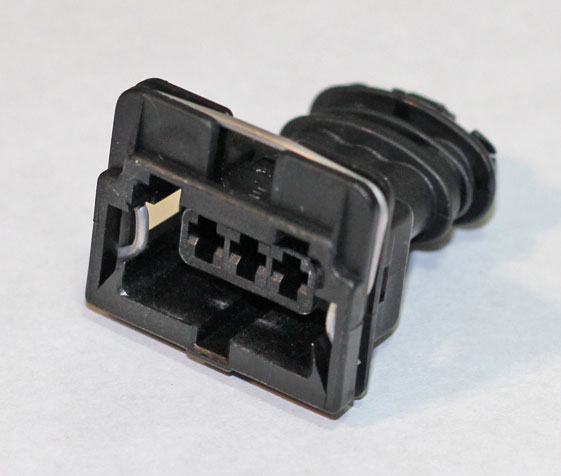
My air valve came in today. What style connectors did you use to connect the wiring?
Zach
Zach
QUOTE(Vacca Rabite @ Jun 8 2017, 09:08 AM)
My air valve came in today. What style connectors did you use to connect the wiring?
Zach
Zach
If it's the 'bosch' style, I have connectors and pins.
QUOTE(Vacca Rabite @ Jun 8 2017, 05:08 AM)
My air valve came in today. What style connectors did you use to connect the wiring?
Zach
I did not have the connector but I used just the small 2.8 mm connectors from Amazon. .
Ahh, the 2pin Bosch connector. I'll throw one in with your VR sensor, Mike. (Shipping today...  )
)
Zach, I'll send one your way too, with a couple AMP35 pins.
)Zach, I'll send one your way too, with a couple AMP35 pins.
Ok so after working with DIY AutoTune it seems I may have an issue with my ECU. This could be causing my ECU to not pick up the signal from the Coil. So an engine drop may not be looming.
But I am still expecting that I will have to drop the engine just because.
But I am still expecting that I will have to drop the engine just because.
QUOTE(McMark @ Jun 8 2017, 09:31 AM)
Ahh, the 2pin Bosch connector. I'll throw one in with your VR sensor, Mike. (Shipping today...
)Zach, I'll send one your way too, with a couple AMP35 pins.
This is why I love the World and the great vendors we have.
Houston we have a problem!
After working with the guys at DIY Autotune, it seems like I may have a hardware problem on the board.
Resistor R20 should measure about 680 ohms. Actually has 681 printed on it.
Measured resistance? 0 ohms!
Of course this makes sense as R20 is in the Option +/- circuit which should give me a tach signal which I never saw out of the system once.
Click to view attachment
Waiting on feedback to see how to address.
Feel pretty good that I did the wiring correctly. The diode should have protected the circuit if it was reversed. But I am not a circuit guy.
Not sure this is a "user replaceable part." At least for this user.
That circuit is weak for filtering the noisy flyback high voltage from the ignition coil. You will have dropped signals at higher RPMs. I strongly recommend aborting on the OPTOIN - and OPTOIN + nonsense circuit and going with the safer trigger wheel route and don't look back.
If you insist on making this work, you should replaced that resistor with a higher wattage and either buy or make a circuit to better shape and condition that noisy incoming signal. Or, have a spare microsquirt handy because if this fails again, it will leave you stranded somewhere, but what do I know
If you insist on making this work, you should replaced that resistor with a higher wattage and either buy or make a circuit to better shape and condition that noisy incoming signal. Or, have a spare microsquirt handy because if this fails again, it will leave you stranded somewhere, but what do I know
QUOTE(timothy_nd28 @ Jun 9 2017, 11:43 AM)
That circuit is weak for filtering the noisy flyback high voltage from the ignition coil. You will have dropped signals at higher RPMs. I strongly recommend aborting on the OPTOIN - and OPTOIN + nonsense circuit and going with the safer trigger wheel route and don't look back.
If you insist on making this work, you should replaced that resistor with a higher wattage and either buy or make a circuit to better shape and condition that noisy incoming signal. Or, have a spare microsquirt handy because if this fails again, it will leave you stranded somewhere, but what do I know
Tim. I really wish you would state your opinion clearly. I find it difficult to decipher your real feelings on this issue!
McMark has the trigger wheel on the way. But I wanted to prove the concept that it I could make it work for the $600 range.
I would like to think I could add the resistor but given the scale I don't think I can do it without causing more concerns.
Click to view attachment
I will start the engine removal this weekend.
QUOTE(timothy_nd28 @ Jun 9 2017, 11:43 AM)
That circuit is weak for filtering the noisy flyback high voltage from the ignition coil. You will have dropped signals at higher RPMs. I strongly recommend aborting on the OPTOIN - and OPTOIN + nonsense circuit and going with the safer trigger wheel route and don't look back.
If you insist on making this work, you should replaced that resistor with a higher wattage and either buy or make a circuit to better shape and condition that noisy incoming signal. Or, have a spare microsquirt handy because if this fails again, it will leave you stranded somewhere, but what do I know
Got a reply back from DIY and they suggested a 1/2 watt resistor mounted off the board?
 They offered to complete the repair no problem. But as Tim said this still has limits. But I think I will send it in for the repair as a back up operation mode.
Received the trigger wheel and goodies from McMark! 
OK so I have not completely read the instructions provided but I thought I would ask if someone had the correct settings for this in regards to teeth and correct angle?
Click to view attachment
Should start the install this weekend.
OK so I have not completely read the instructions provided but I thought I would ask if someone had the correct settings for this in regards to teeth and correct angle?
Click to view attachment
Should start the install this weekend.
I usually start with an Offset Angle of 290°. From your screen grab it looks like the MS2E software call that Tooth #1 Angle.
If nothing happens when you first start with the crank trigger, try swapping the Ignition Input Capture from Falling Edge to Rising Edge. With the MicroSquirt firmware and running ignition, the engine won't start with that setting backwards. So it's pretty easy to tell. You can also figure it out definitively by loading the Tooth Analyzer firmware and looking at the waveform it spits out.
If nothing happens when you first start with the crank trigger, try swapping the Ignition Input Capture from Falling Edge to Rising Edge. With the MicroSquirt firmware and running ignition, the engine won't start with that setting backwards. So it's pretty easy to tell. You can also figure it out definitively by loading the Tooth Analyzer firmware and looking at the waveform it spits out.
QUOTE(McMark @ Jun 8 2017, 01:31 PM)
Ahh, the 2pin Bosch connector. I'll throw one in with your VR sensor, Mike. (Shipping today...
)Zach, I'll send one your way too, with a couple AMP35 pins.
I had not seen this post and got your package in the mail on my birthday earlier this week. THANKS! I was totally surprised.
Zach
QUOTE(Vacca Rabite @ Jun 15 2017, 09:17 AM)
QUOTE(McMark @ Jun 8 2017, 01:31 PM)
Ahh, the 2pin Bosch connector. I'll throw one in with your VR sensor, Mike. (Shipping today...
)Zach, I'll send one your way too, with a couple AMP35 pins.
I had not seen this post and got your package in the mail on my birthday earlier this week. THANKS! I was totally surprised.
Zach


QUOTE(McMark @ Jun 14 2017, 09:18 AM)
I usually start with an Offset Angle of 290°. From your screen grab it looks like the MS2E software call that Tooth #1 Angle.
If nothing happens when you first start with the crank trigger, try swapping the Ignition Input Capture from Falling Edge to Rising Edge. With the MicroSquirt firmware and running ignition, the engine won't start with that setting backwards. So it's pretty easy to tell. You can also figure it out definitively by loading the Tooth Analyzer firmware and looking at the waveform it spits out.
I guess the question I have is relative to TDC what angle is the missing tooth?
The information in the manual is not very clear.
From the manual:
Trigger Angle/Offset (deg)
In 'Toothed Wheel' this should always be set to zero – use tooth #1 angle instead.
Maybe it is that I read things too literal but if it should always be set to 0 and you are to use the #1 angle does that mean tooth #1 has to be at TDC? Or is the missing tooth TDC?
Tooth #1 Angle (deg BTDC)
Generally (with a missing tooth crank wheel) tooth #1 is the first tooth to pass the sensor after the missing tooth gap.
This would seem to follow McMark (290) and suggests that missing tooth should be TDC.
The missing tooth can be anywhere.
The sensor location can be anywhere.
The setting is there to tell the ECU how many degrees between TDC and when it senses the missing tooth. In the case of my trigger wheel, the missing tooth passes the sensor 290(ish) degrees away from TDC.
The sensor location can be anywhere.
The setting is there to tell the ECU how many degrees between TDC and when it senses the missing tooth. In the case of my trigger wheel, the missing tooth passes the sensor 290(ish) degrees away from TDC.
QUOTE(McMark @ Jun 15 2017, 06:24 AM)
The missing tooth can be anywhere.
The sensor location can be anywhere.
The setting is there to tell the ECU how many degrees between TDC and when it senses the missing tooth. In the case of my trigger wheel, the missing tooth passes the sensor 290(ish) degrees away from TDC.
Well that picture certainly clears up a lot of useless gibberish in the manuals!

By the time we are done there will be a lot of useful information in this thread.
QUOTE(Mblizzard @ Jun 15 2017, 10:45 AM)
QUOTE(McMark @ Jun 15 2017, 06:24 AM)
The missing tooth can be anywhere.
The sensor location can be anywhere.
The setting is there to tell the ECU how many degrees between TDC and when it senses the missing tooth. In the case of my trigger wheel, the missing tooth passes the sensor 290(ish) degrees away from TDC.
Well that picture certainly clears up a lot of useless gibberish in the manuals!
By the time we are done there will be a lot of useful information in this thread.
 I have been following this waiting to see how it ends up because I have been thinking about this very conversion to my 2.0 w/carbs
As the reality of modern business becomes more appearemt to all of us in the form of lower expectations, it is great to know we have people like McMark and Orginal Customs who make us understand that there are a few that still share our values and passion.
Just got this in and it is TOP SHELF and is on par with every item I have gotten from Orginal Customs from my complete engine to the smallest part. Well done sir!
Click to view attachment
Just got this in and it is TOP SHELF and is on par with every item I have gotten from Orginal Customs from my complete engine to the smallest part. Well done sir!
Click to view attachment
Progress made today finally. Engine dropped. Taken apart and trigger wheel,added. AC compressor out. Reassembled and ready to slip back in after some wiring and setting the valves.
Click to view attachment
Click to view attachment
Click to view attachment
Click to view attachment
Nice 
QUOTE(timothy_nd28 @ Jun 6 2017, 04:10 PM)
Doug (dlee6204) makes a neat bracket that mounts the sanden compressor on top. I bought his pulley adapter for this conversion but have decided to go a different route, it's all yours if you want it.
I would be interested in that for sure.
Well! Engine back in. Most of the wiring done. All of the things I was going to do with the next engine drop (new starter, change CHT lead, change clutch pull from crap plastic to metal, add SS oil cooler lines, space out oil cooler, and others) done.
Click to view attachment
Click to view attachment
Click to view attachment
Now just have to button up the lose ends and then see if it works!
Click to view attachment
Click to view attachment
Click to view attachment
Now just have to button up the lose ends and then see if it works!
Reviving this thread since I'm just going through configuring one of my MicroSquirt injection setups, but running the MS2Extra firmware.
It appears that the MicroSquirt firmware and the MS2Extra firmware use this 'Trigger Offset' and 'Tooth #1 Angle' differently. I had this car running on the MicroSquirt firmware with a Trigger Offset of 298.2°. Now that I've installed the MS2Extra firmware, it didn't want to start with that as the Tooth #1 Angle setting. I had to go the other direction and put in a setting of 75 to start (which started to run, but barely). Doing the math (360-298.1) gives me 61.8. I'll be tuning the Tooth #1 Angle setting tomorrow with a timing light and will update this post with my final Angle setting.
But this is just another example of how the settings between different firmwares can be drastic, and so if you're researching MegaSquirt settings it's vitally important that you know which firmware corresponds to the information your looking at. A quick web search can send you far down a wrong path if you don't pay attention.
This is a "lo-fi" version of our main content. To view the full version with more information, formatting and images, please click here.