Help - Search - Members - Calendar
Full Version: Today's Research Topic
914World.com > The 914 Forums > 914World Garage
McMark
I inherited a Harbor Freight Leakdown Tester (PN: 94190) from someone and was playing around with it lately, checking out a 2.7 CIS 911 engine that will be going up for sale soon ( shades.gif ).

I learned a few things that I feel should be common knowledge when looking at leakdown results and leakdown testers.

Backstory
I hooked up the HF gauge out of the box and immediately ran into confusion. The instructions indicated that you should pressurize the tester and adjust it to 0% leakage, then hook it to the cylinder and read the leakdown percentage. Well that was a bust, right off the bat. Setting up the gauge as instructed resulted in an inlet pressure of around 35psi. Most people on the internet recommend running a 100psi inlet pressure. So naturally, you would increase the inlet pressure to that recommended level, but the HF then drops to 0% leakdown, as pressure increases.

Initially I thought this was a gauge issue, so I ordered a couple quality pressure gauges from McMaster car and replaced the HF gauges with the McMaster units. This allowed me to compare inlet pressure with cylinder pressure, which is what the leakdown tester is supposed to do. But alas, these numbers still didn't make sense.

What I Learned
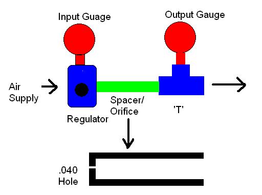
It turns out that a two gauge leakdown tester is showing you inlet pressure on one gauge, which is essentially your compressor pressure, regulated to 100psi (or whatever you choose). The other gauge shows you the pressure inside the cylinder. But between those two gauges there is an orifice (precisely measured small hole). The size of this orifice is EXTREMELY IMPORTANT.

What a leakdown tester is actually showing you is a comparison between the amount of air that can squeeze through the orifice COMPARED to the amount of air that can squeeze through the engine leak path (ring gaps, burned valves, etc). It's more like a ratio than a percentage. So if you think of it as a ratio (Orifice : Leakage), then it's easy to realize that if you change the orifice size you change the ratio, even though the leaks on the engine haven't changed.

Bottom Line
I completely disassembled the HF tester and the orifice in that unit is >2.5mm. While there is no particular standard for leakdown testers MOST units and most people are using a 0.040"/1mm orifice. This is referenced in aircraft leakdown standards, and has basically been adopted by the automotive industry. Posts I found on this subject confirm that expensive testers (such as MAC) come set up with a 1mm orifice.

The HF tester should not be used without modification. My next step is to try plugging the HF orifice and redrilling it to 1mm. This should make my HF gauge work like it should. I'll then reinstall the HF gauges and see how they compare to my quality gauges.

Be wary of leakdown numbers. I'm posting this because it's imperative that anyone who's shopping for 911 engines be aware that it's not enough to simply know the leakdown numbers. You need to know the inlet pressure that was used and the brand of gauge that was used.

IPB Image
tygaboy
Better defining (and demystifying) "important" information.

This PSA brought to you by your friendly neighborhood contributor to the knowledge base that is 914 World.

Thanks Mark! first.gif
76-914
Mark, prior to modifications to the HF tester, did you get some numbers from the HF unit @ 35psi, in order to compare with the unit you are constructing. I'd like to know the % the HF unit is off. beerchug.gif
McMark
QUOTE
I'd like to know the % the HF unit is off.

Unfortunately, it just doesn't work like that. Airflow is not linear. You can't just use a quick formula to translate. The HF orifice @ 2.5mm is so huge and any normal leakage is so small in comparison.

Leakdown percentages are one of those ideas that get passed around, but most people don't stop to think about what the numbers mean. What IS 10% leakdown? 10% of what? You might be tempted to guess that it means 10% of the air in the cylinder leaks out. That's incorrect. If it were correct your engine wouldn't run.

But back to the idea of a scaling calculation-- Using some random airflow calculator I googled, a 2.5mm orifice will flow over 6x as much air as a 1mm orifice at 100psi (in case you doubted airflow isn't linear). So 12% leakdown would scale to 2% leakdown. 911 guys are posting leakdown values of 2%, which even if scaling worked would be 0.333%. Your gauge doesn't read that sort of resolution...

And that's exactly why the 2.5mm orifice is a problem. The orifice is really what sets the scale or resolution. When you say your engine has 10% leakdown, what you're REALLY saying is that your engine has leakage equivalent to 10% of the maximum airflow through a 1mm orifice.

And none of that even accounts for the idea that 35psi is terribly low compared to combustion pressure, which is what we're really trying to get at. How much air/pressure/compression/power is lost to leakage when the fuel ignites. If you're trying to simulate 150-200psi using 35psi you're bound to get inaccurate readings simply because you're not pushing hard enough.
infraredcalvin
Mark, thanks for the info, the extra insight is most appreciated.

I bought a leakdown tester off amazon to check what was going on in my 930 engine (branded as OTC - Chinese made). I was less worried about the final result than comparing the differences between the cylinders. I had 4 that were showing less than 5%, then the final two were well over 30%. One I knew about was due to broken headstuds, the other was due to some carbon buildup hanging up an exhaust valve.

Bottom line is that I was able to get a repeatable baseline on the 4 good ones, then I could compare to the bad. I used a compression tester the same way, with similar findings.
McMark
I read a post on Pelican today that seemed to indicate the OTC setup has a 0.040"/1mm orifice.
euro911
I have 2 of the HF ones. The first one was defective out of the box so they replaced it. I won the other one in a raffle.

How are you going to plug the 2.5mm hole? JB-Weld or something?
McMark
Since I had it completely disassembled I just heated with with a torch and pushed some solder into it. Plugged right up.
euro911
QUOTE(McMark @ May 8 2017, 05:17 PM) *
Since I had it completely disassembled I just heated with with a torch and pushed some solder into it. Plugged right up.
OK. Did you drill the new 1mm orifice through the solder, or adjacent to it?
McMark
I will drill it through the solder. But I'm having trouble finding the drill bit. The small ones break and don't get replaced until the day after I need it. wink.gif
VaccaRabite
I had 2 of the HF units and returned both of them. Got the Blue Case one off ebay that many of us bought a bunch of years ago. Even with my air pressure set at 100PSI to make the math easy (I like to just look at the gauge and read the results), the HF units gave weird results.

Zach
euro911
QUOTE(McMark @ May 9 2017, 07:43 AM) *
I will drill it through the solder. But I'm having trouble finding the drill bit. The small ones break and don't get replaced until the day after I need it. wink.gif
I hear ya on the broken bits dry.gif ... I'll pretty sure my index has the right size bit, or very close to it. I'll be very careful biggrin.gif
This is a "lo-fi" version of our main content. To view the full version with more information, formatting and images, please click here.
Invision Power Board © 2001-2024 Invision Power Services, Inc.