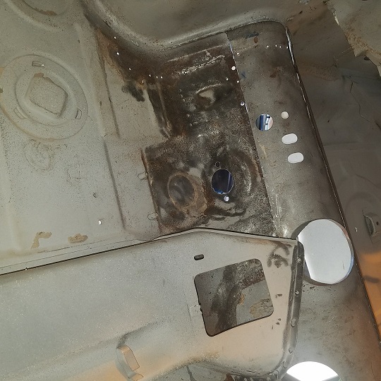
I'm getting ready to patch this bit of floor pan under the master cylinder that isn't included in the RD replacement piece and need some help figuring out how it is supposed to look.
Click to view attachment
A few months ago, I stole this pic from somebody's thread (sorry, I don't remember who) to use as a reference.
Click to view attachment
It looks like the front half of the circle pressed into the floor is slit and raised slightly to allow drainage - I assume in case the mc would leak. Can anyone confirm if that is correct? I ask because there are similarly pressed and slit circles elsewhere on the floor pan, but those are plugged with steel discs and seam sealer. Any insight about how that little spot under the mc is supposed to look and function would be most appreciated!
Full Version: Floor under MC
That slit would be for drainage, but I don't think for the MC. I believe its drainage just for water. I would leave that slit out of your replacement panel.
The other holes with plugs you speak of were used in the manufacturing process for spot welding.
Pete
The other holes with plugs you speak of were used in the manufacturing process for spot welding.
Pete
QUOTE(peteyd @ Jan 4 2018, 08:41 AM) 
That slit would be for drainage, but I don't think for the MC. I believe its drainage just for water. I would leave that slit out of your replacement panel.
The other holes with plugs you speak of were used in the manufacturing process for spot welding.
Pete
Thanks Pete! This confirms that spot was different from the 3 other pressed circles with c-slits and covers (in addition to the 4 holes with bung-style cover plates. I pondered whether that slit was just for draining water (snow and ice melting off shoes for example). I also wondered whether it is a good or bad thing to include that drainage. But it is good to know what the designers intended for that spot.
If they were dipping them bodies you would need drains. They are all over, even the trunk.
QUOTE(Mikey914 @ Jan 4 2018, 09:45 AM)
Are you sure it's for drainage? Because it would also allow water to be introduced into the interior if you were driving in the rain? The likelihood of water needing to be drained vs as driving in the rain, I'd seal it.
There is also the pedal reinforcement that goes underneath that becomes part of the system, I haven't yet looked hard at that to figure out how that would effect water ingress, or whether the aerodynamics would create low pressure in that area to pull liquid out rather than in. I'm always astounded at the cleverness of those German engineers, but yeah, they weren't perfect and did some dumb things too. Part of the fun of working on these cars is getting to play, "Are You Smarter than a Porsche Engineer?" But I guess you play that game every day!

I was also wondering about those plugs and drains - is the common wisdom today to weld all those plugs in place for maximum integrity, given that further spot welding seems unlikely.....
Brent..
Surely someone has a scrap parted out body that they could cut that section out for you..
Anyone??
Surely someone has a scrap parted out body that they could cut that section out for you..
Anyone??
It took me a while to find someone who was chopping up a cancerous hulk and was able to get this section.
Just before that happened I talked to Restoration Design at the Hershey Swap Meet. Though they don't manufacture this panel, they offered to go through their hulks and see if they could find a donor. Give them a call, they might be able to help.
Just before that happened I talked to Restoration Design at the Hershey Swap Meet. Though they don't manufacture this panel, they offered to go through their hulks and see if they could find a donor. Give them a call, they might be able to help.
QUOTE(johnhora @ Jan 4 2018, 12:53 PM)
Brent..
Surely someone has a scrap parted out body that they could cut that section out for you..
Anyone??
QUOTE(somd914 @ Jan 4 2018, 01:15 PM)
It took me a while to find someone who was chopping up a cancerous hulk and was able to get this section.
Just before that happened I talked to Restoration Design at the Hershey Swap Meet. Though they don't manufacture this panel, they offered to go through their hulks and see if they could find a donor. Give them a call, they might be able to help.
Thanks guys, but it's only the small area of that circle that needs to be patched in and should be an easy part to whip out in about an hour. I know that foot box looks like ass, but it's just surface rust beyond that circle. I just finished media blasting it the best I could with the sun in my eyes and shield fogging up, but got it enough to confirm where I have solid metal to tie into. Mainly, I just needed to know exactly what I would be making. There is enough left of mine to make a decent pattern other than knowing details about the drainage. Still haven't decided whether to let it drip or seal it up, but at least now I know what the factory did with it.

This morning, Cary posted an image on Taylor's project thread that solved my mystery:
The image shows the pressed indent I was trying to figure out plugged with a metal disc. As I mentioned before, that circle under the MC looked suspiciously like a row of four circles on the front section of the floor pan. Those circles have U-shaped slits punched in them just like the one in the pic I had stolen as a reference. Here is an example from my old floor pan with the disc removed and sitting next to it:
Click to view attachment
And here is with the disc in place:
Click to view attachment
Just to be sure, I checked the fit of those discs in the remains of what I have under the mc. Perfect fit.
Click to view attachment
So it seems the engineers did not intend there to be drainage in that spot. I agree with Mark that these slits were probably for drainage during dipping processes, and later plugged with the discs. And the larger holes with the bung plugs were for spot welding access like Pete said. So, the inclination to leave that spot sealed is the correct one. I will just hammer form that depression without a hole or slit, but I will cut a new disc to put over it to mimic the factory look. This concludes another episode of Forensic Archeology.
The image shows the pressed indent I was trying to figure out plugged with a metal disc. As I mentioned before, that circle under the MC looked suspiciously like a row of four circles on the front section of the floor pan. Those circles have U-shaped slits punched in them just like the one in the pic I had stolen as a reference. Here is an example from my old floor pan with the disc removed and sitting next to it:
Click to view attachment
And here is with the disc in place:
Click to view attachment
Just to be sure, I checked the fit of those discs in the remains of what I have under the mc. Perfect fit.
Click to view attachment
So it seems the engineers did not intend there to be drainage in that spot. I agree with Mark that these slits were probably for drainage during dipping processes, and later plugged with the discs. And the larger holes with the bung plugs were for spot welding access like Pete said. So, the inclination to leave that spot sealed is the correct one. I will just hammer form that depression without a hole or slit, but I will cut a new disc to put over it to mimic the factory look.
This concludes another episode of Forensic Archeology.
Here's what I wound up doing. My die grinder died on me, so I'll have to clean up those inside welds later.
Click to view attachment
Click to view attachment
Click to view attachment
Click to view attachment
Click to view attachment
Click to view attachment
This is a "lo-fi" version of our main content. To view the full version with more information, formatting and images, please click here.