Full Version: Alternator question.
What is this jumper in the lower left corner of my relay board?
QUOTE(Gatornapper @ Sep 10 2019, 08:37 AM) 
What is this jumper in the lower left corner of my relay board?
That would jump the starter circuit to the fuel pump relay output. It doesn't make sense to be there.
Maybe you have a relay board issue? Did you try another one?
Spoke -
Do not know where/what this is - car is carbureted:
2) Remove the power to the FI ECU (if you have FI). If you have carbs, remove the ground jumper from the FI connector on the relay board. This jumper powers the fuel pump. We want the fuel pump off.
Do not know where/what this is - car is carbureted:
2) Remove the power to the FI ECU (if you have FI). If you have carbs, remove the ground jumper from the FI connector on the relay board. This jumper powers the fuel pump. We want the fuel pump off.
Clay -
Another relay board is being loaned to me and should be here tomorrow.
Should I remove this jumper? No idea why it is there, relay board looks original to car.....
If I remove it, will fuel pump relay still be energized by ignition key ON?
Thanks,
GN
That would jump the starter circuit to the fuel pump relay output. It doesn't make sense to be there.
Maybe you have a relay board issue? Did you try another one?
Another relay board is being loaned to me and should be here tomorrow.
Should I remove this jumper? No idea why it is there, relay board looks original to car.....
If I remove it, will fuel pump relay still be energized by ignition key ON?
Thanks,
GN
QUOTE(ClayPerrine @ Sep 10 2019, 07:42 AM)
That would jump the starter circuit to the fuel pump relay output. It doesn't make sense to be there.
Maybe you have a relay board issue? Did you try another one?
QUOTE(Gatornapper @ Sep 10 2019, 09:42 AM)
Spoke -
Do not know where/what this is - car is carbureted:
2) Remove the power to the FI ECU (if you have FI). If you have carbs, remove the ground jumper from the FI connector on the relay board. This jumper powers the fuel pump. We want the fuel pump off.
The way that jumper is installed, the FP will not run while you crank the engine. When you release the starter, the FP relay is energized through the starter and runs normally.
The front left pin should be connected to ground. This happens in your car when you release the starter.
QUOTE(Gatornapper @ Sep 10 2019, 09:12 AM)
Clay -
Another relay board is being loaned to me and should be here tomorrow.
Should I remove this jumper? No idea why it is there, relay board looks original to car.....
If I remove it, will fuel pump relay still be energized by ignition key ON?
Thanks,
GN
QUOTE(ClayPerrine @ Sep 10 2019, 07:42 AM)
That would jump the starter circuit to the fuel pump relay output. It doesn't make sense to be there.
Maybe you have a relay board issue? Did you try another one?
That jumper hooks the yellow wire for the starter to the output side of the fuel pump relay. It would not power the fuel pump when the car is running.
Like I said, it doesn't make any sense to be there. Without something to energize the ECU relay, the fuel pump relay won't turn on.
It is possible that someone moved the pins around in the harness connectors to the relay board. I would take a long wire, and hook it to the rearmost pin on the relay board where the jumper is. Then touch the other end to the positive battery post. The engine should crank if everything is wired correctly.
QUOTE(Gatornapper @ Sep 10 2019, 09:21 AM)
Ok, will do today.
One additional bit of info: GEN light is OUT when engine is idling.....only comes on with rpm increase, more rpm = brighter GEN light. Bat to chassis when light is OUT is about 12.2 on a fully-charged 12.6 v resting battery.
GN
That the GEN light goes out means the D+ voltage is equal to or near the Bat voltage. In the test that I detailed with the alternator yesterday, the GEN light was out on my car with the alternator unplugged from the relay board even though the VR was in the circuit.
In the run that you describe above, does the GEN light come on with key ON and engine not running?
In the run you describe, with more RPM the GEN light is brighter. It would be interesting to know what the battery voltage is as well as the D+ voltage. They are different but not sure which one is greater than the other.
QUOTE(ClayPerrine @ Sep 10 2019, 10:27 AM)
QUOTE(Gatornapper @ Sep 10 2019, 09:12 AM)
Clay -
Another relay board is being loaned to me and should be here tomorrow.
Should I remove this jumper? No idea why it is there, relay board looks original to car.....
If I remove it, will fuel pump relay still be energized by ignition key ON?
Thanks,
GN
QUOTE(ClayPerrine @ Sep 10 2019, 07:42 AM)
That would jump the starter circuit to the fuel pump relay output. It doesn't make sense to be there.
Maybe you have a relay board issue? Did you try another one?
That jumper hooks the yellow wire for the starter to the output side of the fuel pump relay. It would not power the fuel pump when the car is running.
Like I said, it doesn't make any sense to be there. Without something to energize the ECU relay, the fuel pump relay won't turn on.
It is possible that someone moved the pins around in the harness connectors to the relay board. I would take a long wire, and hook it to the rearmost pin on the relay board where the jumper is. Then touch the other end to the positive battery post. The engine should crank if everything is wired correctly.
The jump powers the FP relay any time the key is in the ON position. In the start position, the FP will not run.
QUOTE(Spoke @ Sep 10 2019, 10:17 AM)
The jump powers the FP relay any time the key is in the ON position. In the start position, the FP will not run.
Per the wiring diagram and lots of years of experience, it won't work that way. If it does, then something has been altered in the wiring or the relay board.
QUOTE(ClayPerrine @ Sep 10 2019, 02:05 PM)
QUOTE(Spoke @ Sep 10 2019, 10:17 AM)
The jump powers the FP relay any time the key is in the ON position. In the start position, the FP will not run.
Per the wiring diagram and lots of years of experience, it won't work that way. If it does, then something has been altered in the wiring or the relay board.
Yeah that jumper connection threw me for a loop too. I didn't think it work work and maybe something was re-wired from the OEM wiring.
However looking at the wire diagram below shows the path to ground for the fuel pump relay coil going through the starter bendix. When the starter is energized the FP turns off. When the key is ON, the FP will run. Not ideal but still operational. It would be best to remove that connection and just ground pin III of the FI connector.
QUOTE(ClayPerrine @ Sep 10 2019, 11:05 AM)
QUOTE(Spoke @ Sep 10 2019, 10:17 AM)
The jump powers the FP relay any time the key is in the ON position. In the start position, the FP will not run.
Per the wiring diagram and lots of years of experience, it won't work that way. If it does, then something has been altered in the wiring or the relay board.
From the relay board wiring diagram I have, it looks like Spoke's right.
Terminal III (top left) goes to the ground terminal on the fuel pump relay, the positive terminal of that relay is fed by the Power Supply relay.
Terminal II and IV (bottom 2) goes directly to the yellow starter wire.
With that configuration, yeah, the only way the relay would find ground is through the starter solenoid when it's NOT energized.
QUOTE(lierofox @ Sep 10 2019, 02:12 PM)
QUOTE(ClayPerrine @ Sep 10 2019, 11:05 AM)
QUOTE(Spoke @ Sep 10 2019, 10:17 AM)
The jump powers the FP relay any time the key is in the ON position. In the start position, the FP will not run.
Per the wiring diagram and lots of years of experience, it won't work that way. If it does, then something has been altered in the wiring or the relay board.
From the relay board wiring diagram I have, it looks like Spoke's right.
Terminal III (top left) goes to the ground terminal on the fuel pump relay, the positive terminal of that relay is fed by the Power Supply relay.
Terminal II and IV (bottom 2) goes directly to the yellow starter wire.
With that configuration, yeah, the only way the relay would find ground is through the starter solenoid when it's NOT energized.
That is not a good way to do it. Very Redneck.
NEVER have any problem starting this engine - is the easiest starting engine of any machine/vehicle I've ever owned - it always starts on the firing of the very first piston - or so it seems.
It does sometimes die after starting tho, and I have to switch the key back to "Off" to engage the starter a 2nd time.
Hard for me to believe the fuel pump isn't pumping when I crank this engine because while it idles terribly, it starts every time. It's never been a problem. Never.
The way that jumper is installed, the FP will not run while you crank the engine. When you release the starter, the FP relay is energized through the starter and runs normally.
The front left pin should be connected to ground. This happens in your car when you release the starter.
It does sometimes die after starting tho, and I have to switch the key back to "Off" to engage the starter a 2nd time.
Hard for me to believe the fuel pump isn't pumping when I crank this engine because while it idles terribly, it starts every time. It's never been a problem. Never.
QUOTE(Spoke @ Sep 10 2019, 08:25 AM)
The way that jumper is installed, the FP will not run while you crank the engine. When you release the starter, the FP relay is energized through the starter and runs normally.
The front left pin should be connected to ground. This happens in your car when you release the starter.
The GEN light is on bright when ignition is ON, engine NOT running - as it should be.
Funny that while I rev the engine up and down, the GEN light goes from Dim/off at idle to bright a 2,000 rpm - while the battery voltage remains fairly constant at 12.2 +/-.
I have not checked the D+ voltage in this scenario - will tomorrow.
Thanks,
GN
Ok, will do today.
One additional bit of info: GEN light is OUT when engine is idling.....only comes on with rpm increase, more rpm = brighter GEN light. Bat to chassis when light is OUT is about 12.2 on a fully-charged 12.6 v resting battery.
GN
That the GEN light goes out means the D+ voltage is equal to or near the Bat voltage. In the test that I detailed with the alternator yesterday, the GEN light was out on my car with the alternator unplugged from the relay board even though the VR was in the circuit.
In the run that you describe above, does the GEN light come on with key ON and engine not running?
In the run you describe, with more RPM the GEN light is brighter. It would be interesting to know what the battery voltage is as well as the D+ voltage. They are different but not sure which one is greater than the other.
Funny that while I rev the engine up and down, the GEN light goes from Dim/off at idle to bright a 2,000 rpm - while the battery voltage remains fairly constant at 12.2 +/-.
I have not checked the D+ voltage in this scenario - will tomorrow.
Thanks,
GN
QUOTE(Spoke @ Sep 10 2019, 08:42 AM)
QUOTE(Gatornapper @ Sep 10 2019, 09:21 AM)
Ok, will do today.
One additional bit of info: GEN light is OUT when engine is idling.....only comes on with rpm increase, more rpm = brighter GEN light. Bat to chassis when light is OUT is about 12.2 on a fully-charged 12.6 v resting battery.
GN
That the GEN light goes out means the D+ voltage is equal to or near the Bat voltage. In the test that I detailed with the alternator yesterday, the GEN light was out on my car with the alternator unplugged from the relay board even though the VR was in the circuit.
In the run that you describe above, does the GEN light come on with key ON and engine not running?
In the run you describe, with more RPM the GEN light is brighter. It would be interesting to know what the battery voltage is as well as the D+ voltage. They are different but not sure which one is greater than the other.
QUOTE(Gatornapper @ Sep 9 2019, 09:26 PM)
Memories guys? Jerry & Zack - Long ago I jumped D+ & DF and did get full 17v at the battery and reported on that numerous times to support my view that the alternator is fine. Even ran the test multiple times.
Also put 12+v to DF as the Pelican article suggests to check all the other diodes, and it too produced a full 14.1 v at the battery, showing all the other alternator diodes are good.
I don't usually remember what I had for lunch, let alone what happened 100 posts ago.

Electrical problems suck! When I was banging my head against the wall over my alternator problems I wanted to just beam Jerry over to my garage. the theory goes over my head really quick.
Zach
I was told to install that jumper for the fuel pump by a few highly respected/knowledgeable on this board ... (for a carbureted motor) 
Clay -
Just to make sure I don't short something out, you mean Pin III, correct?
Think I'll fuse the jumper from 12+ just to be safe.
From all you all are saying, this jumper doesn't make any sense. I get that.
But I can almost certainly assure you that the FP is running while I crank the engine. If it didn't, it seems to me I'd have a lot of dry cranking from time to time.
While this engine has poor compression and doesn't idle, it's the best starting engine I've ever seen. It seems like 1 revolution and she's running - every time.
GN
QUOTE
I would take a long wire, and hook it to the rearmost pin on the relay board where the jumper is. Then touch the other end to the positive battery post. The engine should crank if everything is wired correctly.
Mark -
The first comforting thing I've heard about that jumper - as the Porsche dealer did the carb conversion, the jumper definitely doesn't look like a shade-tree mechanic one, but a very professional one. Note the extra insulation from the terminals back an inch or so....almost like it's a factory jumper....or commercial one.
Some modification would be necessary for fuel pump energizing when eliminating the ECU - as it controlled the fuel pump. So this totally makes sense......
GN
I was told to install that jumper for the fuel pump by a few highly respected/knowledgeable on this board ... (for a carbureted motor)
The first comforting thing I've heard about that jumper - as the Porsche dealer did the carb conversion, the jumper definitely doesn't look like a shade-tree mechanic one, but a very professional one. Note the extra insulation from the terminals back an inch or so....almost like it's a factory jumper....or commercial one.
Some modification would be necessary for fuel pump energizing when eliminating the ECU - as it controlled the fuel pump. So this totally makes sense......
GN
QUOTE(euro911 @ Sep 10 2019, 07:31 PM)
I was told to install that jumper for the fuel pump by a few highly respected/knowledgeable on this board ... (for a carbureted motor)
QUOTE(euro911 @ Sep 10 2019, 09:31 PM)
I was told to install that jumper for the fuel pump by a few highly respected/knowledgeable on this board ... (for a carbureted motor)
This connection has been socialized many times and succinctly documented by SirAndy in this thread:
How To > HOW TO: run the fuel pump for carb conversions, the easy solution!
The fuel pump relay coil is grounded as shown by SirAndy in this picture. What was done on Gatornapper's car is quite unique and not ideal but does work. On his list of things to do on his 914 is correcting this connection.

QUOTE(VaccaRabite @ Sep 10 2019, 09:24 PM)
I don't usually remember what I had for lunch, let alone what happened 100 posts ago.
Zach
I concur.
Although not yet legally in PA... 

QUOTE(Gatornapper @ Sep 10 2019, 09:52 PM)
Mark -
The first comforting thing I've heard about that jumper - as the Porsche dealer did the carb conversion, the jumper definitely doesn't look like a shade-tree mechanic one, but a very professional one....
The jumper is well done and quite unique. The jumper on your 914 definitely stumped the band although it does work. SirAndy's solution is the one you want.
Put it on your list of things to correct. It is not as important as getting the alternator/VR working.
QUOTE(Gatornapper @ Sep 10 2019, 09:22 PM)
Funny that while I rev the engine up and down, the GEN light goes from Dim/off at idle to bright a 2,000 rpm - while the battery voltage remains fairly constant at 12.2 +/-.
Post #23 (on page 2 of now 7):
QUOTE(GregAmy @ May 13 2018, 03:22 PM)
...a slightly different problem: GEN light comes on strong with key on, engine not running, But then the GEN light glows very soft at idle, and then comes on stronger as RPMs build.
Post #36 (also on page 2 of now 7):
QUOTE(GregAmy @ Mar 25 2019, 09:58 PM)
Quick follow up: alternator replacement solved it. I'm guessing a bad diode.
That's such a hateful job...
Replace the alternator.
Edit: print these out in color, and keep them in your manual. As an electrical professional, you can appreciate their value. I've got mine spliced together in a multi-fold so I can expand them out on the toolbox and work through any/all electrical issues...
http://web.archive.org/web/20140328013841/...al_diagrams.htm
Thanks Greg....started doing so on many of the comments here many schematics from the start. Thanks also for the list at Pelican - I've got a lot of their diagrams, but not the list you sent.
Trying $200 Bosche VR and working relay board tonight/tomorrow. If they do not correct things, will rebuild alternator or have it rebuilt. Like you, I suspect they will change nothing.
If the alternator is bad, I want a technical explanation for why it passes all the tests except for the one that counts - working.
Just don't want to rebuild alternator and discover I still have the same problem......since no one can explain why I'm getting these results, I see that as a possibility - one I do not like at all.
GN
Post #23 (on page 2 of now 7):
Post #36 (also on page 2 of now 7):
Quick follow up: alternator replacement solved it. I'm guessing a bad diode.
That's such a hateful job...
Replace the alternator.
Edit: print these out in color, and keep them in your manual. As an electrical professional, you can appreciate their value. I've got mine spliced together in a multi-fold so I can expand them out on the toolbox and work through any/all electrical issues...
http://web.archive.org/web/20140328013841/...al_diagrams.htm
Trying $200 Bosche VR and working relay board tonight/tomorrow. If they do not correct things, will rebuild alternator or have it rebuilt. Like you, I suspect they will change nothing.
If the alternator is bad, I want a technical explanation for why it passes all the tests except for the one that counts - working.
Just don't want to rebuild alternator and discover I still have the same problem......since no one can explain why I'm getting these results, I see that as a possibility - one I do not like at all.
GN
QUOTE(GregAmy @ Sep 11 2019, 05:28 AM)
QUOTE(Gatornapper @ Sep 10 2019, 09:22 PM)
Funny that while I rev the engine up and down, the GEN light goes from Dim/off at idle to bright a 2,000 rpm - while the battery voltage remains fairly constant at 12.2 +/-.
Post #23 (on page 2 of now 7):
QUOTE(GregAmy @ May 13 2018, 03:22 PM)
...a slightly different problem: GEN light comes on strong with key on, engine not running, But then the GEN light glows very soft at idle, and then comes on stronger as RPMs build.
Post #36 (also on page 2 of now 7):
QUOTE(GregAmy @ Mar 25 2019, 09:58 PM)
Quick follow up: alternator replacement solved it. I'm guessing a bad diode.
That's such a hateful job...
Replace the alternator.
Edit: print these out in color, and keep them in your manual. As an electrical professional, you can appreciate their value. I've got mine spliced together in a multi-fold so I can expand them out on the toolbox and work through any/all electrical issues...
http://web.archive.org/web/20140328013841/...al_diagrams.htm
QUOTE(Spoke @ Sep 10 2019, 08:47 PM)
QUOTE(Gatornapper @ Sep 10 2019, 09:52 PM)
Mark -
The first comforting thing I've heard about that jumper - as the Porsche dealer did the carb conversion, the jumper definitely doesn't look like a shade-tree mechanic one, but a very professional one....
The jumper is well done and quite unique. The jumper on your 914 definitely stumped the band although it does work. SirAndy's solution is the one you want.
Put it on your list of things to correct. It is not as important as getting the alternator/VR working. WILL DO!
QUOTE(Gatornapper @ Sep 11 2019, 10:30 AM)
If the alternator is bad, I want a technical explanation for why it passes all the tests except for the one that counts - working.
No one on this forum can provide that information to you.
A local rebuilder might...if you'd take the time to remove the alternator and bring it to them.
I understand that Greg. And I've been thinking of going to rebuilder soon to ask that very question......before I remove the alternator.......
No one on this forum can provide that information to you.
A local rebuilder might...if you'd take the time to remove the alternator and bring it to them.
QUOTE(GregAmy @ Sep 11 2019, 08:53 AM)
No one on this forum can provide that information to you.
A local rebuilder might...if you'd take the time to remove the alternator and bring it to them.
I can understand questioning the health of the alternator in this situation.
However the simple DF to D+ test has the alternator producing 17V at the battery as expected for a good alternator.
An additional test with DF == D+ is to measure the voltage at D+. This should be equal to the battery voltage. This will go towards verifying the diodes are ok in the D+ as well as Battery outputs.
What is unexplained is why the VR produces no voltage at DF with the battery voltage at 12.x volts. The VR should be driving DF significantly if the battery voltage is in the 12.5V range.
Spoke -
May have found the problem, and it is indeed in the alternator.
Met this afternoon with the best mechanic I know in central VA.
The key is what I mentioned at least twice earlier - why, when I hit DF with 12+v and get a full charge at the battery, does the charge quit when I remove the 12v?????
Once charged, the armature should retain its charge - mine does not. For some reason, the armature loses its magnetism - when it should retain it once charged.
My mechanic friend said he has seen this on other bad alternators many times - but no one has ever explained to him WHY it occurs. It renders the alternator bad - even though all the diodes are fully functional.
So I suspect that is what I am dealing with.
GN
I can understand questioning the health of the alternator in this situation.
However the simple DF to D+ test has the alternator producing 17V at the battery as expected for a good alternator.
An additional test with DF == D+ is to measure the voltage at D+. This should be equal to the battery voltage. This will go towards verifying the diodes are ok in the D+ as well as Battery outputs.
What is unexplained is why the VR produces no voltage at DF with the battery voltage at 12.x volts. The VR should be driving DF significantly if the battery voltage is in the 12.5V range.
May have found the problem, and it is indeed in the alternator.
Met this afternoon with the best mechanic I know in central VA.
The key is what I mentioned at least twice earlier - why, when I hit DF with 12+v and get a full charge at the battery, does the charge quit when I remove the 12v?????
Once charged, the armature should retain its charge - mine does not. For some reason, the armature loses its magnetism - when it should retain it once charged.
My mechanic friend said he has seen this on other bad alternators many times - but no one has ever explained to him WHY it occurs. It renders the alternator bad - even though all the diodes are fully functional.
So I suspect that is what I am dealing with.
GN
QUOTE(Spoke @ Sep 11 2019, 12:34 PM)
I can understand questioning the health of the alternator in this situation.
However the simple DF to D+ test has the alternator producing 17V at the battery as expected for a good alternator.
An additional test with DF == D+ is to measure the voltage at D+. This should be equal to the battery voltage. This will go towards verifying the diodes are ok in the D+ as well as Battery outputs.
What is unexplained is why the VR produces no voltage at DF with the battery voltage at 12.x volts. The VR should be driving DF significantly if the battery voltage is in the 12.5V range.
QUOTE(Gatornapper @ Sep 11 2019, 04:42 PM)
Spoke -
May have found the problem, and it is indeed in the alternator.
Met this afternoon with the best mechanic I know in central VA.
The key is what I mentioned at least twice earlier - why, when I hit DF with 12+v and get a full charge at the battery, does the charge quit when I remove the 12v?????
Once charged, the armature should retain its charge - mine does not. For some reason, the armature loses its magnetism - when it should retain it once charged.
My mechanic friend said he has seen this on other bad alternators many times - but no one has ever explained to him WHY it occurs. It renders the alternator bad - even though all the diodes are fully functional.
So I suspect that is what I am dealing with.
GN
About applying D+ to DF through the GEN light and getting 17V at the battery, then no output from the alternator when the D+ to DF connection is removed.
The alternator turning off when DF is disconnected from D+ (ie, interrupting the field current) is what one would expect if the VR is not in place or not functional. The alternator's output is somewhat proportional to the amount of field current and the rotational speed of the alternator. Take away the field current and the alternator stops.
There are lots of confusing data points with your charging systems for sure. I try to avoid swapping components w/o knowing exactly what is wrong. Especially the alternator which is not fun to remove.
There are 2 data points which are consistent with each other:
1) The alternator is not working (duh)
2) The VR is not producing voltage at DF
At this point I would be concerned with why the VR is not driving DF. I detailed a static test with engine not running to check the VR operation.
Here's a good description of an automotive charging system like the 914. Text and link provided.
The Workings Of An Alternator
ALTERNATOR WARNING LIGHT
What does the little red light that says ALT, GEN or sometimes CHARGING mean when it comes on? Without being scientific, it means that either the alternator output voltage is lower than the battery voltage, or the battery voltage is lower than the alternator output voltage. If the light gets dimmer as you rev the engine up, then you most likely have a problem with the alternator. If the light gets brighter, then the battery is most likely the problem.
ALTERNATOR ROTOR
The rotor consists of a coil of wire wrapped around an iron core. Current through the wire coil – called “field” current – produces a magnetic field around the core. The strength of the field current determines the strength of the magnetic field. The field current is D/C, or direct current. In other words, the current flows in one direction only, and is supplied to the wire coil by a set of brushes and slip rings. The magnetic field produced has, as any magnet, a north and a south pole. The rotor is driven by the alternator pulley.
STATOR
Surrounding the rotor is another set of coils, three in total, called the stator. The stator is fixed to the shell of the alternator, and does not turn. As the rotor turns within the stator windings, the magnetic field of the rotor sweeps through the stator windings, producing an electrical current in the windings. Because of the rotation of the rotor, an alternating current is produced.
OUTPUT DIODES
A/C voltage is of little use in a D/C system, such as used in an automobile, so it has to be converted to D/C before it can be used. This conversion to D/C takes place in the “output diodes” and in the “diode trio.” Diodes have the property of allowing current to flow in only one direction, while blocking current flow in the other direction. The output diodes consist of six diodes, one pair for each winding. One of the pair is for the negative half cycle, and the other for the positive half cycle.
DIODE TRIO
The diode trio consists of three diodes, one per phase, which provides field current to the alternator regulator. This output will be discussed in more detail later in the “field current supply” section.
FIELD CURRENT SUPPLY
Field current supply is provided from two different sources – from the alternator itself, via the diode trio, and from the battery, via the alternator warning lamp. When you turn the key to “on”, the engine is not running and the alternator is not spinning. At this time, the voltage/current source for the field current is from the battery, through the ignition switch, and through the warning lamp. After the engine is started, and the alternator is up to speed, the output of the diode trio is fed back to the regulator, and serves as a source of current for the field current. At this time, the alternator is self sustaining, and the battery is no longer needed to power the automobiles electrical system.
REGULATOR
The regulator has two inputs and one output. The inputs are the field current supply and the control voltage input, and the output is the field current to the rotor. The regulator uses the control voltage input to control the amount of field current input that is allow to pass through to the rotor winding. If the battery voltage drops, the regulator senses this, by means of the connection to the battery, and allows more of the field current input to reach the rotor, which increases the magnetic field strength, which ultimately increases the voltage output of the alternator. Conversely, if the battery voltage goes up, less field current goes through the rotor windings, and the output voltage is reduced.
WARNING LIGHT
The alternator warning lamp travels a path to ground from the field current supply input to the voltage regulator. As a result, when the key is turned on, current flows through the warning lamp, through the resisters, transistors, and field coil in the alternator, and then to ground, causing the lamp to illuminate. Once the alternator is at full output its voltage will equal the battery voltage. At this time, with 12 volts on both sides, the lamp is out. If the alternator should fail, voltage from the diode trio would drop, and once again the lamp would light from the battery voltage. If the alternator output is only a little low, the lamp will be dimly lit. If the alternator fails completely, and the output voltage goes to zero, the lamp will be lit at full brilliance. Conversely, if the battery should fail, and the battery voltage drops, with the output voltage of the alternator on one side and the low battery voltage on the other, the lamp will also light. As stated earlier, if the light grows dimmer as the engine is revved up, it is because the alternator voltage is rising with the RPM, producing more voltage on the alternator side of the lamp. The closer the output voltage gets to the battery voltage, the dimmer the bulb becomes. By the same way, if the light gets brighter with increasing RPM, it is because as the alternator voltage increases, it is getting higher than the battery voltage. The higher the voltage with respect to the battery voltage, the greater the voltage difference across the lamp, and the brighter it gets.
The Workings of An Alternator
QUOTE(Spoke @ Sep 11 2019, 04:05 PM)
At this point I would be concerned with why the VR is not driving DF. I detailed a static test with engine not running to check the VR operation.
Precisely. Running your static test on 4 different VR's this am: Original, NOS, AC-Delco SS (probably made in China but copy of German one), and new Bosche loaned me by 914Sixer.
If none are producing voltage at DF, we know that's why system is not charging - and problem is neither in the VR nor the alternator.
914Sixer also loaned me a good relay board - that will be the next test if none of the VR's produce voltage at DF. What a gracious forum member Mark is. But we all already knew that, right?
GN
Is there any chance one of the VR sockets on the relay board have pushed through the potting and are not making solid contact with the VR? Maybe there enough that you can probe it, but not enough for the VR to really plug in? Its really hard to see it looking at the relay board, but easy to feel if you reach under the board.
Zach
Zach
Zach -
Thanks man, but swapped a good relay board yesterday another member loaned me - no change. So relay board is fine.
The expensive Bosche VR he loaned me did produce a solid 13.1 volts at the battery too, but not 14.1, and the Gen light stayed on.
I only ran it for a few minutes, then put my cheap SS AC-Delco one back in and now the Gen light stays OUT! But voltage at battery is only 12.2 to 12.4. Drove car in city for an hour in heavy traffic, thinking when I got home the battery would be discharged in the 11 volt range.
Nope. 12.36 volts. Normal resting voltage on this new gel battery is 12.65, so it was down a little, but not much.
I retract what I said about alternator being bad. Spoke clarified that the armature is simply an electro-magnet with windings as they all have - and all electro-magnets lose their magnetism when no voltage is on the windings. So the armature needs voltage all the time to work. And the armature IS getting voltage because I do have a charging voltage of 12.2 to 12.4. Apparently this is sufficient for daytime driving with no other electrical loads.
So I may just run this VR until I drop the engine for a top-end rebuild in the next 6 or so months.......
GN
Is there any chance one of the VR sockets on the relay board have pushed through the potting and are not making solid contact with the VR? Maybe there enough that you can probe it, but not enough for the VR to really plug in? Its really hard to see it looking at the relay board, but easy to feel if you reach under the board.
Zach
Thanks man, but swapped a good relay board yesterday another member loaned me - no change. So relay board is fine.
The expensive Bosche VR he loaned me did produce a solid 13.1 volts at the battery too, but not 14.1, and the Gen light stayed on.
I only ran it for a few minutes, then put my cheap SS AC-Delco one back in and now the Gen light stays OUT! But voltage at battery is only 12.2 to 12.4. Drove car in city for an hour in heavy traffic, thinking when I got home the battery would be discharged in the 11 volt range.
Nope. 12.36 volts. Normal resting voltage on this new gel battery is 12.65, so it was down a little, but not much.
I retract what I said about alternator being bad. Spoke clarified that the armature is simply an electro-magnet with windings as they all have - and all electro-magnets lose their magnetism when no voltage is on the windings. So the armature needs voltage all the time to work. And the armature IS getting voltage because I do have a charging voltage of 12.2 to 12.4. Apparently this is sufficient for daytime driving with no other electrical loads.
So I may just run this VR until I drop the engine for a top-end rebuild in the next 6 or so months.......
GN
QUOTE(VaccaRabite @ Sep 12 2019, 06:43 PM)
Is there any chance one of the VR sockets on the relay board have pushed through the potting and are not making solid contact with the VR? Maybe there enough that you can probe it, but not enough for the VR to really plug in? Its really hard to see it looking at the relay board, but easy to feel if you reach under the board.
Zach
Going to put a volt-meter in the cabin. Can someone advise me on where an original volt-meter would get its positive signal? Where I should tap the wiring for a 12v signal that will switch off with the ignition?
TIA,
GN
TIA,
GN
Cigar litter is always hot.
QUOTE(Gatornapper @ Sep 13 2019, 08:53 AM)
Zach -
Thanks man, but swapped a good relay board yesterday another member loaned me - no change. So relay board is fine.
The expensive Bosche VR he loaned me did produce a solid 13.1 volts at the battery too, but not 14.1, and the Gen light stayed on.
I only ran it for a few minutes, then put my cheap SS AC-Delco one back in and now the Gen light stays OUT! But voltage at battery is only 12.2 to 12.4. Drove car in city for an hour in heavy traffic, thinking when I got home the battery would be discharged in the 11 volt range.
13.1 is acceptable - the battery is charging. 12.2 - 12.4 isn't. You have resistance somewhere and it will strand you eventually... I was where you are now last summer.
At around 11.5 volts your car starts running rough running. By 10.6 or so your car is dead. but your flashers will still work while you wait for the tow truck. And then you get to post on the Flatbed thread.
Zach
Just found this on Pelican's site for a rebuilt Bosche alternator - surprised I've never seen this issue before - this guy says the problem exists on multiple alternators he has......seems this would explain what's going on with my system. Of course, I won't know until I pull my alternator........
===================================
Andrew B.
October 25th, 2016
Rear cover can short circuit
This alternator doesn't come with the rear cover plate and wiring harness. You have to transfer those parts from your old alternator.
There is an un-insulated terminal on the back side of the alternator, labelled B+ (positive connection from the battery) That terminal can ground against the back cover plate, making a short circuit ground from the battery. The terminal has both a nut sticking up and a wide washer under the nut. I covered the washer with a ring of paper gasket material, held in place with a dab of RTV silicon, and then covered the nut with a small plastic cap, again held with RTV silicon. The Porsche parts diagrams show a gasket under the back cover plate. That would help space the cover up to clear this terminal, but that gasket was missing from my old alternator, and it is not included with this new one. I cut a new gasket from 1/16" paper gasket material and installed it under the cover. Checking the 3 or 4 old alternators I had in my parts collection, sure enough, they all have blobs or sealant or other somewhat jury rigged looking solutions to this problem. Bosch should really be providing an insulated cover for this terminal, or a back cover plate with more clearance."
GN
With all the measurement of voltages being discussed around Gatornapper's charging issues, I decided to take a few measurements of my 914 in which the charging system is working as expected.
If a charging system (alternator, VR, battery) is being evaluated for some issue, one should always think about taking a "set" of measurements to get a good feel for the health of the system. That set would include:
1) Battery voltage
2) D+ voltage at VR or alternator plug
3) DF voltage at VR or alternator plug
4) D- voltage at VR or alternator plug
Each measurement is taken with respect a chassis hard point. Not the battery negative or engine or transmission. Use either the stud behind the relay board or the stud behind the battery.
I took a couple of sets of measurements today after a 10 minute drive. 4 sets of measurements were taken:
1) At idle w/o headlights
2) at 2k RPM w/o headlights
3) at idle headlights ON
4) at 2k RPM headlights ON
First set at idle w/o headlights.
VBAT: 13.5Vdc
D+: 13.5-13.8Vdc bouncing around
DF: 12Vdc
D-: -25mv
at 2k RPM w/o headlights.
VBAT: 13.6Vdc
D+: 13.95Vdc steady
DF: 5Vdc
D-: -66mv
at idle headlights ON.
VBAT: 12.6Vdc
D+: 13.5Vdc
DF: 11.3Vdc
D-: -31mv
at 2k RPM headlights ON.
VBAT: 13.4Vdc
D+: 13.6Vdc
DF: 6Vdc
D-: -120mv
All 4 sets of these measurements took less than 5 minutes total. Notice VBAT and D+ are always within 1V of each other. This indicates the 6 steering diodes pointing to VBAT and D+ are in good shape.
Since the magnetic field generated by the armature is rotational speed dependent, as the RPM increased the VR dropped the voltage to the field windings (about 12V down to 5-6V) to keep the output voltage constant.
Notice the voltage of D- increases with increased alternator load maxing out at -0.12V with lights on at 2k RPM.
Spoke -
Just saw this for first time since back from our family vacation.....I'll take the same readings today or tomorrow with the new Bosche VR that does charge (13.4 at bat) but has the GEN light on almost all the time.
Today or tomorrow.......
GN
With all the measurement of voltages being discussed around Gatornapper's charging issues, I decided to take a few measurements of my 914 in which the charging system is working as expected.
If a charging system (alternator, VR, battery) is being evaluated for some issue, one should always think about taking a "set" of measurements to get a good feel for the health of the system. That set would include:
1) Battery voltage
2) D+ voltage at VR or alternator plug
3) DF voltage at VR or alternator plug
4) D- voltage at VR or alternator plug
Each measurement is taken with respect a chassis hard point. Not the battery negative or engine or transmission. Use either the stud behind the relay board or the stud behind the battery.
I took a couple of sets of measurements today after a 10 minute drive. 4 sets of measurements were taken:
1) At idle w/o headlights
2) at 2k RPM w/o headlights
3) at idle headlights ON
4) at 2k RPM headlights ON
First set at idle w/o headlights.
VBAT: 13.5Vdc
D+: 13.5-13.8Vdc bouncing around
DF: 12Vdc
D-: -25mv
at 2k RPM w/o headlights.
VBAT: 13.6Vdc
D+: 13.95Vdc steady
DF: 5Vdc
D-: -66mv
at idle headlights ON.
VBAT: 12.6Vdc
D+: 13.5Vdc
DF: 11.3Vdc
D-: -31mv
at 2k RPM headlights ON.
VBAT: 13.4Vdc
D+: 13.6Vdc
DF: 6Vdc
D-: -120mv
All 4 sets of these measurements took less than 5 minutes total. Notice VBAT and D+ are always within 1V of each other. This indicates the 6 steering diodes pointing to VBAT and D+ are in good shape.
Since the magnetic field generated by the armature is rotational speed dependent, as the RPM increased the VR dropped the voltage to the field windings (about 12V down to 5-6V) to keep the output voltage constant.
Notice the voltage of D- increases with increased alternator load maxing out at -0.12V with lights on at 2k RPM.
Just saw this for first time since back from our family vacation.....I'll take the same readings today or tomorrow with the new Bosche VR that does charge (13.4 at bat) but has the GEN light on almost all the time.
Today or tomorrow.......
GN
QUOTE(Spoke @ Sep 15 2019, 06:47 PM)
With all the measurement of voltages being discussed around Gatornapper's charging issues, I decided to take a few measurements of my 914 in which the charging system is working as expected.
If a charging system (alternator, VR, battery) is being evaluated for some issue, one should always think about taking a "set" of measurements to get a good feel for the health of the system. That set would include:
1) Battery voltage
2) D+ voltage at VR or alternator plug
3) DF voltage at VR or alternator plug
4) D- voltage at VR or alternator plug
Each measurement is taken with respect a chassis hard point. Not the battery negative or engine or transmission. Use either the stud behind the relay board or the stud behind the battery.
I took a couple of sets of measurements today after a 10 minute drive. 4 sets of measurements were taken:
1) At idle w/o headlights
2) at 2k RPM w/o headlights
3) at idle headlights ON
4) at 2k RPM headlights ON
First set at idle w/o headlights.
VBAT: 13.5Vdc
D+: 13.5-13.8Vdc bouncing around
DF: 12Vdc
D-: -25mv
at 2k RPM w/o headlights.
VBAT: 13.6Vdc
D+: 13.95Vdc steady
DF: 5Vdc
D-: -66mv
at idle headlights ON.
VBAT: 12.6Vdc
D+: 13.5Vdc
DF: 11.3Vdc
D-: -31mv
at 2k RPM headlights ON.
VBAT: 13.4Vdc
D+: 13.6Vdc
DF: 6Vdc
D-: -120mv
All 4 sets of these measurements took less than 5 minutes total. Notice VBAT and D+ are always within 1V of each other. This indicates the 6 steering diodes pointing to VBAT and D+ are in good shape.
Since the magnetic field generated by the armature is rotational speed dependent, as the RPM increased the VR dropped the voltage to the field windings (about 12V down to 5-6V) to keep the output voltage constant.
Notice the voltage of D- increases with increased alternator load maxing out at -0.12V with lights on at 2k RPM.
I recently bought this car and it has some electrical "issues". Some PO in it's life thought he was an electrician when he was a spaghetti chef. I've seen more organized wiring in a can of Chef-Boyardee.
I am having charging issues. It is not charging. I did a drive last Saturday night and it left me stranded about a mile from the house. It died in front of a friends house so I left it there over night and towed it home the next day. I left it on the trickle charger all week and it fired right up yesterday.
Here are the symptoms I am seeing.
I am not getting the light on with the key in and turned on. I'm thinking I need to replace the bulb as my starting point. Does anyone have specs/part number on a proper replacement bulb?
I am getting 12 volts across the battery posts on an analog multimeter
I placed a jumper wire between D+ and DF. Started the car and the multimeter showed no voltage change at the battery posts.
Correct me if I am wrong but the light failure should not be an issue when I jumper D+ and DF. Jumpering D+ and DF effectively bypass the light.
Based on what I am seeing, I need to replace the bulb and the alternator.
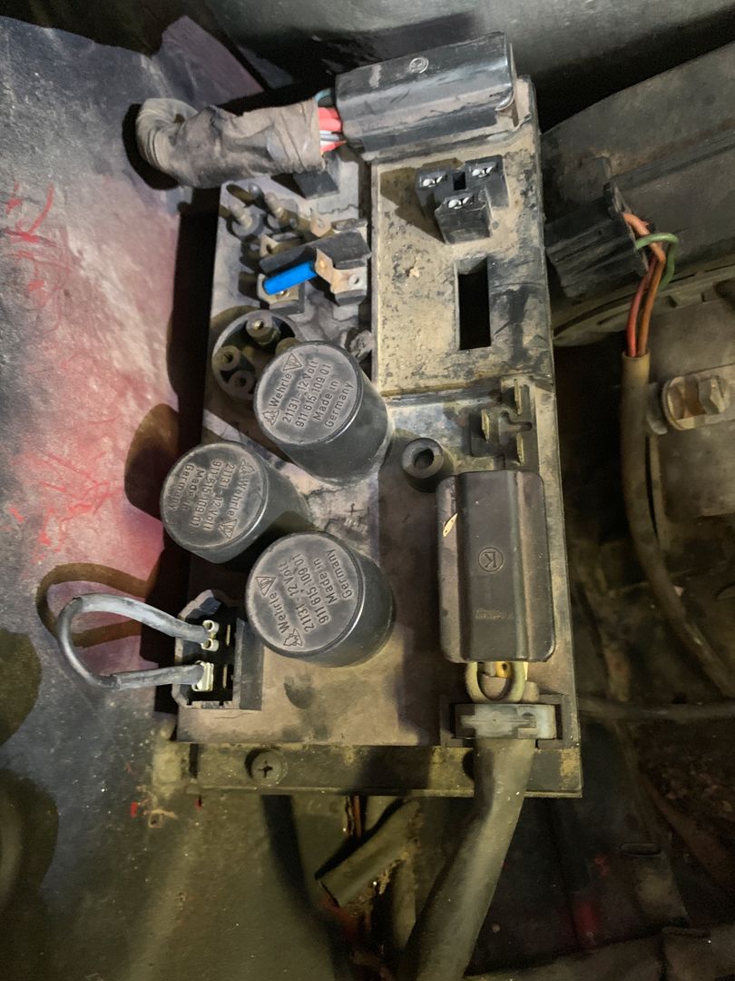
The car is running carbs and here is a picture of the relay board. It looks to be missing a few things.
Click to view attachment
The yellow wire that comes down from the top of the pic and goes over and connects to the screw for the engine tin is the ground wire some PO(S) installed for the license plate lights. The white wire is the other license plate light wire. It goes from where you can see it in this picture, up through a hole that was drilled in the firewall, down behind the back pad, along the drivers side long and then up into the dash by the driver door hinges.
The other/silver "wire" connected to the same engine tin screw is a stainless steel cable that I think was installed as some kind of ground strap.(The other option is that it is there to keep the engine in place while accelerating so the massive torque doesn't rip the engine right out of the car... Yeah, I'm going with dumb @$$ PO ground strap attempt . )
The green wire goes(went) down to the starter solenoid and had four splices in it including the two you can see. Each splice was a different gauge of wire. It is/was the PO(S) attempt at a replacement for the factory yellow wire that goes down to the solenoid. I just couldn't deal with looking at it so I replaced it with a single yellow wire in the correct gauge with much better routing.
The fuel pump comes on when I turn the key to the on position. This is controlled by a switch under the dash which turns the fuel pump on and off when the key is in the on position.
There is some additional non-factory wiring in the tunnel that looks like it is not connected to anything in the engine compartment. I will remove it as I have time to work on the car.
On a semi related note, where is the best place to get the cloth tape the factory used to wrap the wiring harness?
Click to view attachment
I am having charging issues. It is not charging. I did a drive last Saturday night and it left me stranded about a mile from the house. It died in front of a friends house so I left it there over night and towed it home the next day. I left it on the trickle charger all week and it fired right up yesterday.
Here are the symptoms I am seeing.
I am not getting the light on with the key in and turned on. I'm thinking I need to replace the bulb as my starting point. Does anyone have specs/part number on a proper replacement bulb?
I am getting 12 volts across the battery posts on an analog multimeter
I placed a jumper wire between D+ and DF. Started the car and the multimeter showed no voltage change at the battery posts.
Correct me if I am wrong but the light failure should not be an issue when I jumper D+ and DF. Jumpering D+ and DF effectively bypass the light.
Based on what I am seeing, I need to replace the bulb and the alternator.
The car is running carbs and here is a picture of the relay board. It looks to be missing a few things.
Click to view attachment
The yellow wire that comes down from the top of the pic and goes over and connects to the screw for the engine tin is the ground wire some PO(S) installed for the license plate lights. The white wire is the other license plate light wire. It goes from where you can see it in this picture, up through a hole that was drilled in the firewall, down behind the back pad, along the drivers side long and then up into the dash by the driver door hinges.
The other/silver "wire" connected to the same engine tin screw is a stainless steel cable that I think was installed as some kind of ground strap.(The other option is that it is there to keep the engine in place while accelerating so the massive torque doesn't rip the engine right out of the car... Yeah, I'm going with dumb @$$ PO ground strap attempt .
)The green wire goes(went) down to the starter solenoid and had four splices in it including the two you can see. Each splice was a different gauge of wire. It is/was the PO(S) attempt at a replacement for the factory yellow wire that goes down to the solenoid. I just couldn't deal with looking at it so I replaced it with a single yellow wire in the correct gauge with much better routing.
The fuel pump comes on when I turn the key to the on position. This is controlled by a switch under the dash which turns the fuel pump on and off when the key is in the on position.
There is some additional non-factory wiring in the tunnel that looks like it is not connected to anything in the engine compartment. I will remove it as I have time to work on the car.
On a semi related note, where is the best place to get the cloth tape the factory used to wrap the wiring harness?
Click to view attachment
QUOTE(AZBanks @ Oct 5 2019, 09:46 PM)
I placed a jumper wire between D+ and DF. Started the car and the multimeter showed no voltage change at the battery posts.
Correct me if I am wrong but the light failure should not be an issue when I jumper D+ and DF. Jumpering D+ and DF effectively bypass the light.
Check the bulb resistance with your multimeter. If it is open, it needs to be replaced. Not sure what wattage it is. Someone else should chime in on that.
Jumping D+ to DF will not get the alternator started if the bulb is not in the circuit. The bulb provides a bit of armature field current to get the alternator started. Then D+ will pull up DF and the alternator will produce maximum output of about 17V.
Spoke -
Bulb is fine, lights brightly both with ignition on, engine not running, and when engine is running.
Remember? I checked to make sure it was 2 watt, which it was, and I still put in a new one.
Weird thing is new Bosch VR charges fine - but GEN light stays on most of the time. New SS VR - light is off, but max. voltage to battery is 12.4 to 12.6.
Still have to do the tests you listed....been busy.....
GN
I placed a jumper wire between D+ and DF. Started the car and the multimeter showed no voltage change at the battery posts.
Correct me if I am wrong but the light failure should not be an issue when I jumper D+ and DF. Jumpering D+ and DF effectively bypass the light.
Check the bulb resistance with your multimeter. If it is open, it needs to be replaced. Not sure what wattage it is. Someone else should chime in on that.
Jumping D+ to DF will not get the alternator started if the bulb is not in the circuit. The bulb provides a bit of armature field current to get the alternator started. Then D+ will pull up DF and the alternator will produce maximum output of about 17V.
Bulb is fine, lights brightly both with ignition on, engine not running, and when engine is running.
Remember? I checked to make sure it was 2 watt, which it was, and I still put in a new one.
Weird thing is new Bosch VR charges fine - but GEN light stays on most of the time. New SS VR - light is off, but max. voltage to battery is 12.4 to 12.6.
Still have to do the tests you listed....been busy.....
GN
QUOTE(Spoke @ Oct 6 2019, 10:36 PM)
QUOTE(AZBanks @ Oct 5 2019, 09:46 PM)
I placed a jumper wire between D+ and DF. Started the car and the multimeter showed no voltage change at the battery posts.
Correct me if I am wrong but the light failure should not be an issue when I jumper D+ and DF. Jumpering D+ and DF effectively bypass the light.
Check the bulb resistance with your multimeter. If it is open, it needs to be replaced. Not sure what wattage it is. Someone else should chime in on that.
Jumping D+ to DF will not get the alternator started if the bulb is not in the circuit. The bulb provides a bit of armature field current to get the alternator started. Then D+ will pull up DF and the alternator will produce maximum output of about 17V.
I think Spoke's response was for me. Sorry to hijack your thread. I'm having the same or at least a similar issue to what you are facing so I jumped in here instead of creating a new thread.
Spoke -
Bulb is fine, lights brightly both with ignition on, engine not running, and when engine is running.
Remember? I checked to make sure it was 2 watt, which it was, and I still put in a new one.
Weird thing is new Bosch VR charges fine - but GEN light stays on most of the time. New SS VR - light is off, but max. voltage to battery is 12.4 to 12.6.
Still have to do the tests you listed....been busy.....
GN
I placed a jumper wire between D+ and DF. Started the car and the multimeter showed no voltage change at the battery posts.
Correct me if I am wrong but the light failure should not be an issue when I jumper D+ and DF. Jumpering D+ and DF effectively bypass the light.
Check the bulb resistance with your multimeter. If it is open, it needs to be replaced. Not sure what wattage it is. Someone else should chime in on that.
Jumping D+ to DF will not get the alternator started if the bulb is not in the circuit. The bulb provides a bit of armature field current to get the alternator started. Then D+ will pull up DF and the alternator will produce maximum output of about 17V.
QUOTE(Gatornapper @ Oct 7 2019, 01:17 PM)
Spoke -
Bulb is fine, lights brightly both with ignition on, engine not running, and when engine is running.
Remember? I checked to make sure it was 2 watt, which it was, and I still put in a new one.
Weird thing is new Bosch VR charges fine - but GEN light stays on most of the time. New SS VR - light is off, but max. voltage to battery is 12.4 to 12.6.
Still have to do the tests you listed....been busy.....
GN
QUOTE(Spoke @ Oct 6 2019, 10:36 PM)
QUOTE(AZBanks @ Oct 5 2019, 09:46 PM)
I placed a jumper wire between D+ and DF. Started the car and the multimeter showed no voltage change at the battery posts.
Correct me if I am wrong but the light failure should not be an issue when I jumper D+ and DF. Jumpering D+ and DF effectively bypass the light.
Check the bulb resistance with your multimeter. If it is open, it needs to be replaced. Not sure what wattage it is. Someone else should chime in on that.
Jumping D+ to DF will not get the alternator started if the bulb is not in the circuit. The bulb provides a bit of armature field current to get the alternator started. Then D+ will pull up DF and the alternator will produce maximum output of about 17V.
I picked up a set of dash light bulbs from the bird. I thought I was getting one bulb so I ordered two. Turn out, I got two sets. If anyone needs a dash light bulb, let me know and I'll drop one in the mail, I have PLENTY!
I swapped out the bulb and nothing changed. Still no light when the key is in the on position.
I swapped out the bulb and nothing changed. Still no light when the key is in the on position.
QUOTE(AZBanks @ Oct 11 2019, 08:42 PM)
I swapped out the bulb and nothing changed. Still no light when the key is in the on position.
Assume you're talking about the GEN light. Please get your voltmeter, start the car, measure:V+, VD, V-, and Battery to chassis. So much information about the state of the charging system is contained in one of these charging voltage sets. Please take all 4 measurements at the same time. Should take about 1 minute. Write them down and let me know what they are.
This is a "lo-fi" version of our main content. To view the full version with more information, formatting and images, please click here.