Welding update…. It’s DONE! (well mostly, I’m sure I’ll find more to do if I look hard enough)
I spent some time cleaning up the areas that won’t be accessible after I get it assembled. So I put some primer and paint in the areas around the firewall and gas tank as well as under where the suspension will be mounted. Since the underside was previously painted black, I finished it off with a black matte.
My next step was to attach the front suspension.
Easier said than done.
First I needed to mount the clutch master cyl. But, I wanted to mount it in the proper position not upside down as it was.. I found out quickly that they did it for a reason, because the master and the steering rack wants to occupy the same space. I’m sure a couple of you already told me that, but I had to try. So that means I had to bleed the clutch master right side up before mounting it upside down. That also means I had to connect the clutch slave, and the clutch slave bracket, but that means I had to reassemble the oil pickup tube and oil pan. Having done all that I realized that the clutch throwout lever wasn’t engaging properly so I had to pull the trans back and reengage it correctly. I had previously pulled the transaxle out but not put it back in correctly. (There are no books on this)
Ok, where was I (are you still following this?) Can you see why this is taking so long?
Now the transaxle is back in, correctly engaging the throwout bearing. The gearshift cables are re-connected. The slave cylinder is connected, and guess what. It didn’t need bleeding. It works great.
So now I need to flip the slave cyl over to gain room for the steering rack and then…
mount the wildwood brackets and pedals,
mount the front suspension,
run the fuel line, fuel pump, filters, fuel tank, etc
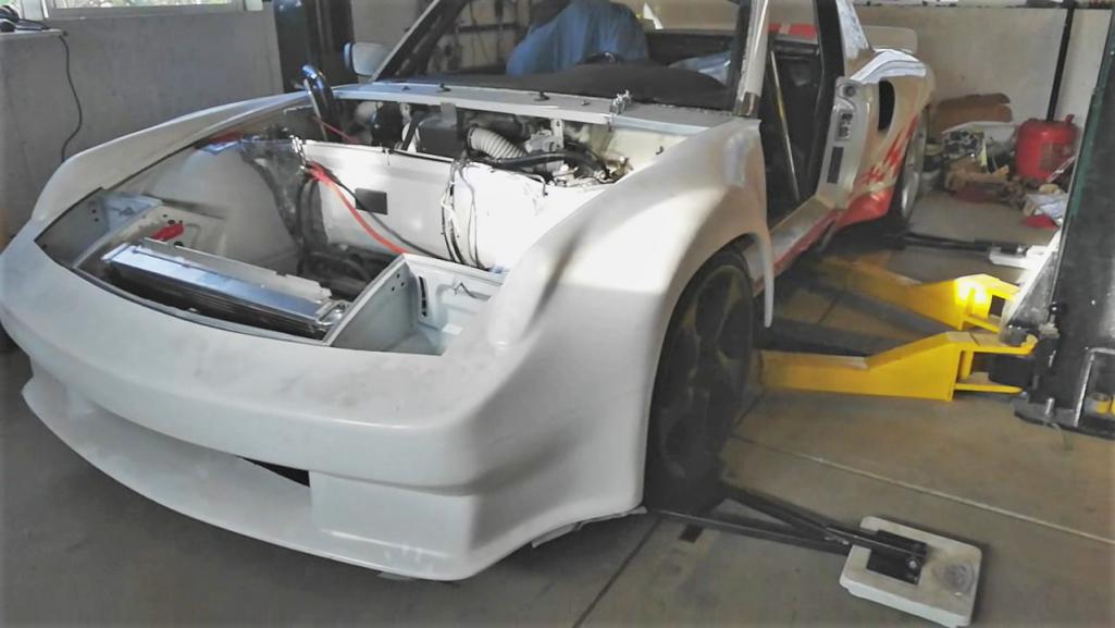
cut out the opening for the radiator, fab up radiator mounting brackets, etc. run the hoses.
Reassemble the heater, vent hoses, and water lines to the heater core.
Cut out turn signal light openings in the fiberglass fenders. Then mount those lights.
I also have to do the one part that is still 914. That is assemble the headlight buckets.
Now comes the fun part. Wiring it all back up. I labeled it all and marked it down on paper and lots of photos. But it will still be ‘fun’.
I left out an important part. That is mounting the fiberglass fender and front bumper assembly. So I’ll probably insert that in to the mix where appropriate. Oh and the windshield install. And the door. And a tune-up. And the seat mod, and roll bar mods. And some day I’ll get to paint…
So, there are a few bits to accomplish in the next month before the first autocross.


![popcorn[1].gif](http://www.914world.com/bbs2/style_emoticons/default/popcorn[1].gif)
