I have a 1974 914 with a 1.8 ltr. engine and L-Jet injection. The fuel injection harness does not plug into the four prong connector on the relay board. I understand this is correct for the model. However, there is a wire embedded in the wrapped cable of the 12 pole connector housing from the ignition harness with a female connection. There is no apparent connection. Can you shed any light on that wire and where it should be connected? mschafer51@outlook.com
Full Version: Engine Bay Relay Board
A picture would help
That wire activates the fuel pump when cranking. It goes on either of the rear terminals in the 4 pin block on the left rear corner of the board.
Per the wire diagram the yellow wire goes to pin II at the 4 pin connector on the relay board.
That is the rear most inside pin.
That pin is energized by the starter power so the FI gets a signal that the engine is being cranked over.
Jim
That is the rear most inside pin.
That pin is energized by the starter power so the FI gets a signal that the engine is being cranked over.
Jim
Is the car still starting and running?
IIRC from when I re-wired the race car to remove the relay board, the yellow wire is actually from the ignition switch (and/or seat belt interlock relay) to send power to the starter solenoid.
From that photo, it appears that the original yellow wire is still intact inside the wiring harness, that this loose yellow wire is connected to that factory yellow wire going to the relay board. The factory yellow wire goes through the relay board circuit to exit the T12 connector - also via a yellow wire - to the starter solenoid. If your starter is still turning when you select the crank position on the ignition switch, and the yellow wire is still going to the starter solenoid, then that's the case.
It is within the relay board, via the T4b connector, that power goes to the ECU during cranking to have it energize the fuel pump.
So, given all that, your question becomes: what did someone want to power up during cranking? And why would they do that, given that this circuit is borderline-capable to begin with (which is why many of us relay that circuit)?
Greg, he has an Ljet car. You are describing a Djet car arrangement. Different animals.
QUOTE(JeffBowlsby @ May 9 2019, 09:49 AM) 
Greg, he has an Ljet car. You are describing a Djet car arrangement. Different animals.
Ah. So the D-Jet starter circuit is wired differently?
That thin yellow wire in the Ljet ignition harness is the stock configuration, not modified as you were suggesting, and goes to the Ljet dual dual relay. You are confusing it with the thicker yellow solenoid activating wire which is inside the harness casing.
Handy to know, Jeff; thanks!
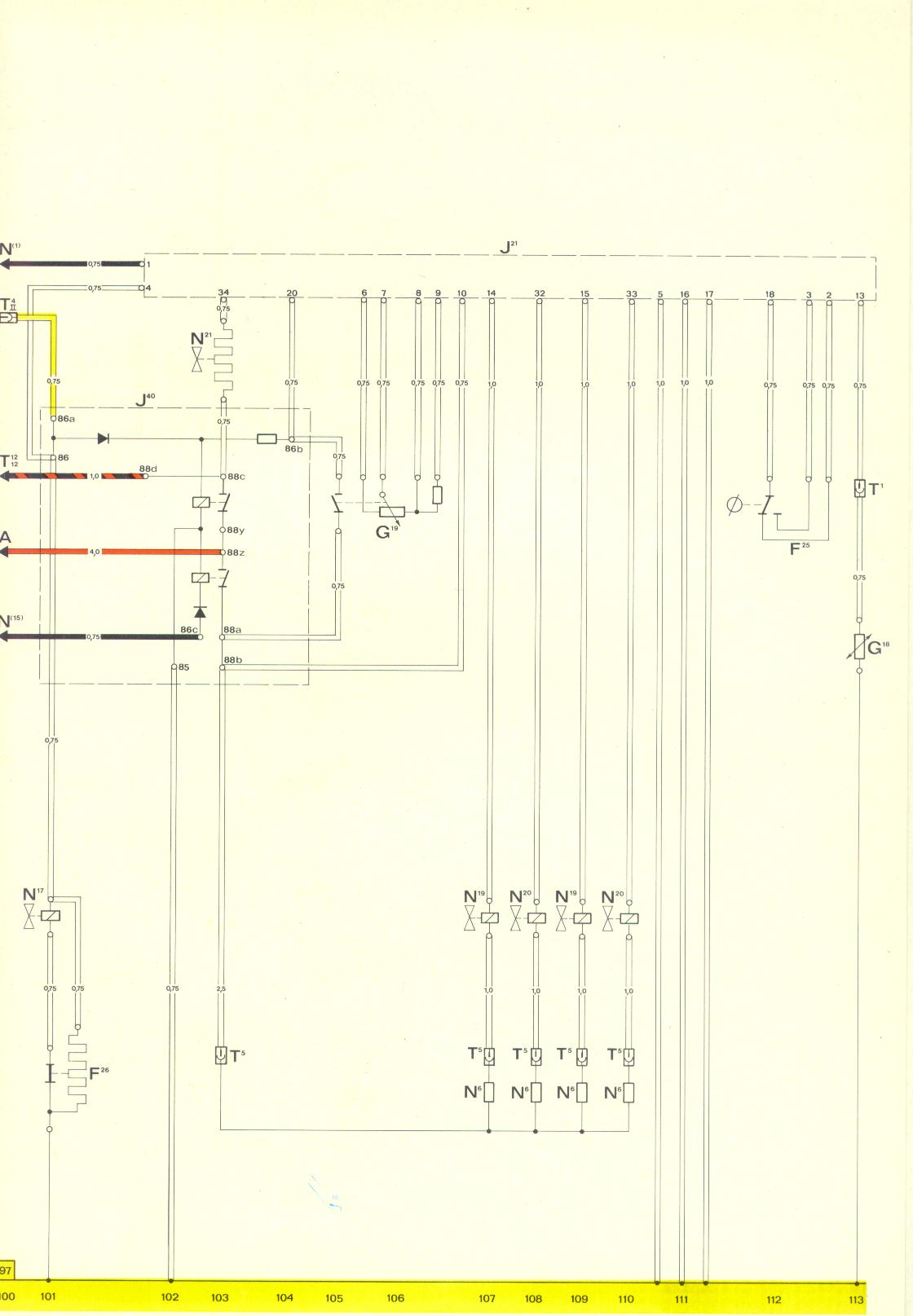
Interesting that the factory wiring diagram for the '74 AFC illustrates the wire to the double relay (J40) comes off T4-II:
http://web.archive.org/web/20130403002222i...ic_74_AFC-B.jpg
Interesting that the factory wiring diagram for the '74 AFC illustrates the wire to the double relay (J40) comes off T4-II:
http://web.archive.org/web/20130403002222i...ic_74_AFC-B.jpg
QUOTE(GregAmy @ May 9 2019, 09:48 AM)
Handy to know, Jeff; thanks!
Interesting that the factory wiring diagram for the '74 AFC illustrates the wire to the double relay (J40) comes off T4-II:
http://web.archive.org/web/20130403002222i...ic_74_AFC-B.jpg
Thanks for the info
QUOTE(GregAmy @ May 9 2019, 08:48 AM)
Handy to know, Jeff; thanks!
Interesting that the factory wiring diagram for the '74 AFC illustrates the wire to the double relay (J40) comes off T4-II:
The yellow wiring in the diagram is the yellow wire in the picture that the OP asked about.
T4-II ties into the starter circuit through the relay panel, so while cranking T4-II has power to it.
L-jet does not cycle the fuel pump when the key is on, it turns on the fuel pump while the starter is operating and when enough air is sucked through the air flow meter to open the flap slightly.
Jim
Thank you all for your comments
Downrange
Downrange
This is a "lo-fi" version of our main content. To view the full version with more information, formatting and images, please click here.