OK guys - we have some very talented people here and I'm hoping to bring my wiring skills up a level.
What separates amateur wiring from a pro level? One item that comes to mind - no use of Harbor Freight connectors (which I am guilt of).
What else comes to mind?
Full Version: Differences between amateur and professional wiring?
Solder your crimp fittings to take it to the next level. All solder joints should be shiny when completed. Connectors should be marine grade heat shrink style that require a heat gun to complete. Wiring should be bundled neatly and routed in a manner that does not cause stress on any of the wires. Wires should be of the required size, color coded or labeled in a manner that makes identification easy. That should get your started. The real pros will chime in shortly. 
EDIT: buy a good set of crimpers. They'll be north of $70
EDIT: buy a good set of crimpers. They'll be north of $70
Wire should be SAE Type GPT wire at minimum. Use proper crimp connectors, not the cheap crap you find at Autozone or Walmart.
Proper Crimpers and tools go a long way. Heat shrink, strain relief, and proper wire looming
But it is very hard to say what Pro wiring surely is. As various levels are used across multiple industries.
Soldering should not be used in an automotive strand wire application.
I would use heat shrink with adhesive.
Then if your stepping up to the top level your going to go with wiring that has been twisted, and loomed together, and using high end connectors. Weather-pack are like the low end connectors, and it just climbs in cost and complexity from there.
Wiring goes up, if you see anything that says MIL on it, run, it will cost you $$$$.
Label everything, and then clear heat shrink the label. They actually make printers that print onto heat shrink, I still add clear over it to keep it protected.
After that I can say I build all my wiring on paper first, then in string, then on a board or bench, then in wire.
Not a pro anymore, I used to wire up one-off prototype stuff, it was all MIL spec, and all in white, with numbers at each end. And a spreadsheet was used to keep it all straight. You can get the MIL spec wire in colors other than white, it was just easier in our application to stock white and use it for everything.
http://www.visioneng.com/wp-content/upload...rol.15SEP16.pdf
I learned a lot from this site. I'm kinda an advanced amateur.
....Soldering should not be used in an automotive strand wire application.
Why Not?
I learned a lot from this site. I'm kinda an advanced amateur.
....Soldering should not be used in an automotive strand wire application.
Why Not?
QUOTE(76-914 @ Jan 3 2020, 08:26 PM) 
Solder your crimp fittings to take it to the next level.
EDIT: buy a good set of crimpers. They'll be north of $70
Agree completely that you need a good set of crimpers. Note that crimpers are specific to the type of termination you are using (Spade, Molex, Weatherpack, Deutsch, Amphenol, etc.). 914's use really low end spade connectors which are really low tech but cheap and easy to fix which has it merits. Mac Tools and Snap-on both have some nice crimers that basically roll the crimp inward rather than simply crushing it from both sides like cheap crimping pliers.
QUOTE(bandjoey @ Jan 3 2020, 09:00 PM)
....Soldering should not be used in an automotive strand wire application.
Why Not?
Beware of soldering vehicle wiring. The solder wicks up into the wire and creates a non flexible termination. If the soldered termination is subject to vibration (and it will be in a car) it will fatigue and crack over time. I know there are DoD military vehicles with soldered connections and I can tell you horror stories about that wiring and associated military style Amphenol connectors. Likewise I've seen plenty of race cars with soldered connections. Some good, some terrible. Race cars are not typically subjected to decades of use. Not saying don't ever solder but minimize it and for sure don't over do the solder and have it wicking up into the wire beyond where the crimp ends. Personally no solder for me.
Trying to create a shrink wrap strain relief often creates more havoc that what it was intended to prevent. Automotive wiring needs flexibilty at its termination to survive. Nothing wrong with a little bit of strain relief where harness split's into Y formations though. Again, don't over do it. Flexibility is critical to survival.
You will not find soldered connectors (other than on a mid harness splice) on modern vehicles. Not for cost but rather that you want the flexibility of a crip termination and the lack of vibration fatigue problems.
As previously referenced what sets the men from the boys:
1) Neatness. Braided sheath, convolute, or simple wiring tape really makes it tidy.
2) Leaving enough service length so the connector isn't severely flex'd and so it can be removed later without stressing the wire.
3) Properly crimped connections. Crimp them, then pull on them - hard, they should not slip or give. A properly crimed connector will not let lose before the wire itself breaks.
4) Color coding and consistency. Don't be cheap. Buy quality wires with unique tracer markings. Plenty of sources for vintange and German wiring colors.
https://www.riwire.com/
Look at Jeff Bowlsby's wiring harness designs. Very nice and a good benchmark to shoot for.
I'll just add a little to the already excellent advice given. You can buy OEM (AMP) connectors at digikey. They are high quality and an exact match of what came originally in these cars. Here is a list of some of the part numbers I used rebuilding my harness:
Click to view attachment
You can use generic grommets but OEM are still available but a bit of a PITA to source. Most of the grommets are blanked sealing grommets so IMO, using open style grommets is not at a professional level as they won't seal out water or air like the originals. Here is a list of part numbers for most of the grommets. If you want the spreadsheet that includes source links, PM your email address.
Click to view attachment
As for soldering, follow the earlier advice and do not solder terminal connectors for the reasons @Superhawk996 described. From what I have read, soldered terminal connections are not allowed in aviation applications. That says something. However, DO solder wire splices if you have to make them. Use a lineman's splice , solder it, and protect it with heat sink. I match the heat sink color to the wire and add match tracers with colored sharpies just for that extra touch.
914Rubber sells OEM harness tape if you want to match the original. You can also get it on ebay. I think the brand is Telsa but can't remember for sure.
Hope this helps.
Click to view attachment
You can use generic grommets but OEM are still available but a bit of a PITA to source. Most of the grommets are blanked sealing grommets so IMO, using open style grommets is not at a professional level as they won't seal out water or air like the originals. Here is a list of part numbers for most of the grommets. If you want the spreadsheet that includes source links, PM your email address.
Click to view attachment
As for soldering, follow the earlier advice and do not solder terminal connectors for the reasons @Superhawk996 described. From what I have read, soldered terminal connections are not allowed in aviation applications. That says something. However, DO solder wire splices if you have to make them. Use a lineman's splice , solder it, and protect it with heat sink. I match the heat sink color to the wire and add match tracers with colored sharpies just for that extra touch.
914Rubber sells OEM harness tape if you want to match the original. You can also get it on ebay. I think the brand is Telsa but can't remember for sure.
Hope this helps.
QUOTE(bbrock @ Jan 3 2020, 09:37 PM)
Here is a list of some of the part numbers I used rebuilding my harness:

That is an incredibly useful list of small parts. Thank you for sharing. It must have taken a ton of time to research all those part numbers.
@SirAndy
That list should get moved somewhere for ease of acess long after this thread disappears off the front page.
If you are a bit detail obsessed like me, I found that brake cleaner, hard nylon brush, then a soapy water can clean up a tired existing harness pretty well. Rewrap it with new cloth tape from HD.
Also I would add new fuse terminal block to the four main high amp feed wires (10 ga. red) coming off your battery terminal block. I think the stock setup is a bit under designed in my opinion (mine was) Cheap easy insurance.
Also I would add new fuse terminal block to the four main high amp feed wires (10 ga. red) coming off your battery terminal block. I think the stock setup is a bit under designed in my opinion (mine was) Cheap easy insurance.
That is a really good guide!
The Home built aircraft “industry” is a good place to find high quality advice, tools and supplies. One of the go to sources is https://www.steinair.com/. They can supply a wide variety of wiring supplies of good quality in the type of quanties appropriate to our kind of use. Maybe of most value is that they have sorted through the quality maze and provide great quality vs. value for the hobbiest/near professional
In addition, this ste http://www.aeroelectric.com/articles.html#...20and%20Splices Is a wealth of knowledge on all things electrical in layman’s terms. It is focused on aviation but there is a lot of elementary how to stuff there about correct solder joints, crimping, termination etc. written by a guy known as Electric Bob in the home builders world. Entertaining writer and also a very KISS engineer.
Not affiliated to either
QUOTE(AZBanks @ Jan 4 2020, 02:48 AM)
Awesome link to behind the scences of high end Motorsport wiring.
Two great quotes that reflect the unfortunate ugly side of motorsports
"A person we know used to wire high end off the road racing vehicles where the total wiring bill was often North of $25,000.00 for parts and labor and he did not want to do it anymore as it was tough getting paid for the work, not to mention all the travel and fighting clients. "
"We once built a new harness for a long term racing project, ready for installation. Due to unrealistic attitudes and unappreciative recipients we simply cut up the harness and saved the connectors. Expensive lesson."
QUOTE(Costa05 @ Jan 3 2020, 10:43 PM)
If you are a bit detail obsessed like me, I found that brake cleaner, hard nylon brush, then a soapy water can clean up a tired existing harness pretty well. Rewrap it with new cloth tape from HD.
Also I would add new fuse terminal block to the four main high amp feed wires (10 ga. red) coming off your battery terminal block. I think the stock setup is a bit under designed in my opinion (mine was) Cheap easy insurance.
Agree here, I had to install a new to me main harness & was afraid of a short somewhere.
here's my new fuze box.
Click to view attachment
Dont use any kind of tape to wrap your harness with (yes it may be original but there are better options available) I used the braided nylon sleeving often found in industrial robots etc when I did my aftermarket ECU install. Just terminate the ends with heatshrink with glue and it looks great.
+1 on the correct crimping tools and also get a proper set of pliers for removing the insulation on the cables. Its worth the $20 instead of using the old worn sidecutter !
+1 on the correct crimping tools and also get a proper set of pliers for removing the insulation on the cables. Its worth the $20 instead of using the old worn sidecutter !
I thought this would be a useful topic, thanks for all of the great discussion and information.
Are there any specific crumpets recommendated?
Are there any specific crumpets recommendated?
My recommendations from https://www.steinair.com/product-category/tools/page/2/
SKU: SAT-001 crimpers
SKU: SAT-030 crimper dies
SKU: SAT-018 pin crimper
SKU: SAT-005 wire strippers
The crimper and dies for crimping insulated terminals, the pin crimper for connector pins and un-insulated terminals, and the wire strippers for general use.
Have fun
SKU: SAT-001 crimpers
SKU: SAT-030 crimper dies
SKU: SAT-018 pin crimper
SKU: SAT-005 wire strippers
The crimper and dies for crimping insulated terminals, the pin crimper for connector pins and un-insulated terminals, and the wire strippers for general use.
Have fun
I've been really happy with this budget crimping set for occasional DIY use.
https://www.amazon.com/gp/product/B00Y7M7SG...=UTF8&psc=1
https://www.amazon.com/gp/product/B00Y7M7SG...=UTF8&psc=1
QUOTE(bandjoey @ Jan 3 2020, 08:00 PM)
http://www.visioneng.com/wp-content/upload...rol.15SEP16.pdf
I learned a lot from this site. I'm kinda an advanced amateur.
....Soldering should not be used in an automotive strand wire application.
Why Not?
I completely disagree with the comment about not soldering the wires. That is an old wives tale. If you take a close look at a factory 914 harness, you will find that every connection on it is soldered. When I rebuilt the DME harness for the 4.0L motor, every connection on it was soldered when I disassembled it. If you do it right, soldering the connections is a very good, reliable connection.
QUOTE(ClayPerrine @ Jan 5 2020, 01:46 PM)
QUOTE(bandjoey @ Jan 3 2020, 08:00 PM)
http://www.visioneng.com/wp-content/upload...rol.15SEP16.pdf
I learned a lot from this site. I'm kinda an advanced amateur.
....Soldering should not be used in an automotive strand wire application.
Why Not?
I completely disagree with the comment about not soldering the wires. That is an old wives tale. If you take a close look at a factory 914 harness, you will find that every connection on it is soldered. When I rebuilt the DME harness for the 4.0L motor, every connection on it was soldered when I disassembled it. If you do it right, soldering the connections is a very good, reliable connection.
 never had an issue with soldering once I got good @ it
  .
.QUOTE(barefoot @ Jan 4 2020, 08:29 AM)
QUOTE(Costa05 @ Jan 3 2020, 10:43 PM)
If you are a bit detail obsessed like me, I found that brake cleaner, hard nylon brush, then a soapy water can clean up a tired existing harness pretty well. Rewrap it with new cloth tape from HD.
Also I would add new fuse terminal block to the four main high amp feed wires (10 ga. red) coming off your battery terminal block. I think the stock setup is a bit under designed in my opinion (mine was) Cheap easy insurance.
Agree here, I had to install a new to me main harness & was afraid of a short somewhere.
here's my new fuze box.
Click to view attachment
Exactly. That is a clean install.
QUOTE(ClayPerrine @ Jan 4 2020, 07:46 PM)
I completely disagree with the comment about not soldering the wires. That is an old wives tale. If you take a close look at a factory 914 harness, you will find that every connection on it is soldered. When I rebuilt the DME harness for the 4.0L motor, every connection on it was soldered when I disassembled it. If you do it right, soldering the connections is a very good, reliable connection.
There is material science behind the recommendation. It is not an old wives tale.
A stranded wire that is soldered esentially becomes a larger gauge solid wire. That singular wire then work hardens due to vibration. With enough time and vibration it will break.
The analogy is to take a coat hanger (single strand wire). Now begin bending it back and forth (i.e. low frequency vibration). Eventually it work hardens and breaks. if you speed up the the bending (vibration frequency) or the amount you bend the wire (the vibration amplitude) the faster it breaks.
Copper work hardens in the same way that steel does though it takes longer.
This is the reason automotive uses stranded wire. Multiple smaller gauge wires are more flexible than a singe larger strand and work harden over a much longer period of time.
I'm not sure what harness you're looking that is soldered. There are many crimped spade connectors that have a bit of insulation over the spade to prevent shorts but the connections underneath are crimped not soldered.
The sole exception that I'm aware of is I think the 14 way engine harness "bullets" are soldered at the very end. They are then inserted into the 14 way plastic connector and capped / clamped in position such that those little bullets are not exposed to vibration the way the rest of the spade connectors in the engine compartment are. The wires coming out of that 14 way harness are able to flex freely. I would go look to be sure but my engine harness is currently in storage. Going from memory the only other connector that uses those soldered bullets is the trans reverse switch which is notorious for breakage.
Having been professionally trained on alll methods and techniques of soldering, and having repaired thousands of wiring harnesses over the years, I will continue to disagree with you.
The problem with soldering connections is not with the soldering. If you do it right, and don't extend the solder past the end of the metal on the connector, you don't damage the copper strands when you strip the wire, and you put proper strain reliefs on the wire, then you will have a good connection.
The problem with soldering connections is not with the soldering. If you do it right, and don't extend the solder past the end of the metal on the connector, you don't damage the copper strands when you strip the wire, and you put proper strain reliefs on the wire, then you will have a good connection.
QUOTE(ClayPerrine @ Jan 5 2020, 04:33 AM)
Having been professionally trained on alll methods and techniques of soldering, and having repaired thousands of wiring harnesses over the years, I will continue to disagree with you.
The problem with soldering connections is not with the soldering. If you do it right, and don't extend the solder past the end of the metal on the connector, you don't damage the copper strands when you strip the wire, and you put proper strain reliefs on the wire, then you will have a good connection.
I agree 100% I have been building, repairing and troubleshooting elevators in some of the tallest buildings in Manhattan for the past 33 years, talk about vibration! When done properly, a good solder, is the best form of connection, the reason the aviation industry shuns it is human error is higher and temperatures vary greatly. I have removed wires from 40 years of service in a 50 story building with no soldering issues, due to the well trained men who came before me, mostly Military trained, so done properly, it’s the most effective.
I think You are both right.
For our purposes, well done crimps (using better quality tools and materials) will yield excellent results.
Good soldering is a bit harder and more involved skill to master (as implied by Tjmrfe). I reserve it for use on splices and crimp joints where gas tight joints are hard to achieve ( large gauge wires and terminations)
And of course proper use of shrink tube for sealing and strain relief.
If you can master these basic skills you can build some reliable and good looking wiring.
@ClayPerrine Clay you are 100% correct, but an amateur going to professional should not be soldering wires into a harness. You have proper training it is 100% effective, key is proper training.
For a guy to go down the street grab some crap solder and soldering iron, and start soldering up a harness. We hav all done dumb things at one time and still might be we are all someone else's Dumb Previous Owner. I have found through many years working many different industries that I can always find someone better than me. And they intern can point to someone better than them.
Clay you are 98% better than most of use on this board at what you know and have learned, and I am sure you can point out a few people who are better still.
Soldering has it place, but it should be a pro class item. I solder stuff all the time, but it has the proper strain reliefs.
I have torn into enough cars to know that you don't give an untrained person a soldering Iron and say fix that. What you end up with is a bunch of crap, and more repairs. If you spend anytime around boats or trailers you learn the average Joe does some pretty stupid stuff.
To make the transition from amateur to professional requires the willingness to learn the craft, what ever craft it is, and then constantly learn as the techniques and technologies continue to advance. Then put in the dedicated hours honing to become a master.
For a guy to go down the street grab some crap solder and soldering iron, and start soldering up a harness.
We hav all done dumb things at one time and still might be we are all someone else's Dumb Previous Owner. I have found through many years working many different industries that I can always find someone better than me. And they intern can point to someone better than them.Clay you are 98% better than most of use on this board at what you know and have learned, and I am sure you can point out a few people who are better still.
Soldering has it place, but it should be a pro class item. I solder stuff all the time, but it has the proper strain reliefs.
I have torn into enough cars to know that you don't give an untrained person a soldering Iron and say fix that. What you end up with is a bunch of crap, and more repairs. If you spend anytime around boats or trailers you learn the average Joe does some pretty stupid stuff.
To make the transition from amateur to professional requires the willingness to learn the craft, what ever craft it is, and then constantly learn as the techniques and technologies continue to advance. Then put in the dedicated hours honing to become a master.
Stephen, pretty much what I was trying to say.
I have spent a lot of well intended time making way more trash soldering than I have made crimping - that includes connectors in my kit built airplane where I thought soldering would be “better”
Ended up cutting out most of those crappy efforts and honing my crimping skills with good tools, materials, techniques and results.
Thank god for planning in service loops.
The thought of service loops got me thinking further -
For me one of the marks that distinguishes amateur from pro wiring is a pros wiring uses only the amount of wire necessary. In other words he has the confidence to cut wires to the perfect length the first time knowing that his termination technique/skill (soldering or crimping) will be right the first time. The result is a tidy looking job with all wires carrying even strain, no loops, S bends or tangled crossovers.
That is what I strive for as an amateur and only achieve sometimes.
QUOTE(ClayPerrine @ Jan 5 2020, 07:33 AM)
Having been professionally trained on alll methods and techniques of soldering, and having repaired thousands of wiring harnesses over the years, I will continue to disagree with you.
The problem with soldering connections is not with the soldering. If you do it right, and don't extend the solder past the end of the metal on the connector, you don't damage the copper strands when you strip the wire, and you put proper strain reliefs on the wire, then you will have a good connection.
 That's OK. The beautiful thing is that each of us is free to do as we see fit on our personal vehciles. I have nothing but respect for the you and the vehicles you've built. You do awesome work and I don't mean to imply anything negative about your craftsmanship. It is impressive!
 Honestly, I'm aligned to what you are saying that if soldering is done PROPERLY there is little risk in automotive applications IF the wire isn't subject to vibration stress.
However, the reality is that most people are not competent at soldering. The tools and the techniqes are far more complicated than the tools required for crimping. It takes training and lots of practice to get soldering right. I say that as USAF trained electronics technician. Nicked wiring from improper stripping, seen it. Overheated wires that melt and degrade the wire insulation, seen it. Underheated wires with a blob of solder just basically sticking two wires together in a high resistance joint, seen it. Improperly designed stress relief that is bent too tightly, and creates intermittent connections as wires vibrate, seen it. Too much solder flux and not cleaned leading to corrosion later on, seen it. Not enough flux, seen it. The list of potential soldering flaws goes on and on.
But let's at least be factual about this. A proper crimp is superior and this isn't just my personal opinion or a desire to disagree with you personally or any of the other posters in favor of soldering. The fact that crimping is superior is based on unimaginable test hours conducted by NASA, automotive OEM's, and the global aviation industry on vibration tables and wiring harness test rigs that most readers of this forum have never seen. It is not just a personal opinion or old wives tale.
"Crimping is an efficient and highly reliable method to assemble and terminate conductors, and typically provides a stronger, more reliable termination method than that achieved by soldering." Excerpted from NASA document.
Click to view attachment
https://workmanship.nasa.gov/lib/insp/2%20b...s/frameset.html
See section 2.01 for source of the quote and the graphic.
The previous post from @AZBanks on high end motorsports wiring was priceless. Long but incredibly thorough so i won't rehash that one but it was worth reading in full. The craftsmanship & planning that is required to produce F1 level wiring harness is amazing. That truly is what separates professional from amatuer work which was the point of the OP.
QUOTE(AZBanks @ Jan 4 2020, 02:48 AM)
Here is an example of a medium sized vibration test table. There are tables used that are much larger than this. Now envision that with a complete wiring harness with representative wiring harness attachments and/or instrument panel and other related modules mounted to it and subjected to known road load vibration profiles and duty cycle testing. Sorry I couldn't find one with wiring on it

https://www.youtube.com/watch?v=etUNYZP_yHA
And of course for automotive, 4 post shakers are commonly used by all OEM's for testing and development of full vehicles. Typically 4 posters are not used for durability work like proving out a wiring harness but it gives you some insight into the massive size of some of the vibration test equipment available and the vibration stress that the harness will be subjected to. Here is a neat 7 post shaker being used for suspension development. Skip the first 20 seconds of the nose cone testing.
https://www.youtube.com/watch?v=_SPflUyT1rQ
Simply put, crimps are better if you don't know what you are doing with solder! This argument will probably go on forever, but my experience says solder is better.
A solder joint is always better electrically and vibration will not be an issue if the harness is routed and supported correctly. Solder weeping up a copper wire is controlled by PROPER soldering techniques. Placing the heat in the right place and using a wire heat sink will prevent solder from creeping up the wire. I was taught to NASA standards in a Naval shipyard and worked to exacting standards on wiring and connectors for nuclear instrumentation on nuclear powered naval ships. I have done a lot of soldering from circuit cards to large power carrying wires. One thing most folks overlook when soldering is cleanliness of the parts to be soldered! Dirty wire and connectors cause bad solder joints. We examined completed solder joints under a microscope for holes due to dirt. If there were holes, solder came off/out and re-cleaned and re-soldered until it passed inspection.
Soldered connections remove the chance of corrosion from interfering with the wire to connector connection. There are other ways to help keep corrosion away from the connector to wire joint such as heat shrink connectors using a PROPER crimping tool and heat gun. One area I worked in had a large drawer full of crimpers, in excess of 50, for different size and application. We had engineering provide the type and size of crimper, wire, and connector to use for each connection type.
I could go on all day with stories of wiring and connectors and how they interact with the end use and environment they are subjected to in engine rooms. Think of heat, humidity, oils, and vibration.
Tom
PS: If you are going to do a lot of soldering, do it in a well ventilated area with a fan blowing gently to move the vapors away from you. The lead in solder can cause problems with your health.
You all missed the most effective wire connection. Second only to speed tape.
original colored wires and sized correctly, solder, and heat shrink tubing. NOTHING less
OK guys - we have some very talented people here and I'm hoping to bring my wiring skills up a level.
What separates amateur wiring from a pro level? One item that comes to mind - no use of Harbor Freight connectors (which I am guilt of).
What else comes to mind?
QUOTE(Tdskip @ Jan 3 2020, 06:12 PM)
OK guys - we have some very talented people here and I'm hoping to bring my wiring skills up a level.
What separates amateur wiring from a pro level? One item that comes to mind - no use of Harbor Freight connectors (which I am guilt of).
What else comes to mind?
QUOTE(bandjoey @ Jan 3 2020, 09:00 PM)
http://www.visioneng.com/wp-content/upload...rol.15SEP16.pdf
I learned a lot from this site. I'm kinda an advanced amateur.
....Soldering should not be used in an automotive strand wire application.
Why Not?
The crimping examples here make it really clear on why you need a quality crimper.
Thanks for sharing this.
Thanks to all who have contributed their information on this very interesting topic.
The links to the NASA and RBRacing (and others) sites are certainly illuminating and well worth studying.
I've learned a lot....Thanks!
The links to the NASA and RBRacing (and others) sites are certainly illuminating and well worth studying.
I've learned a lot....Thanks!
Whether you solder or crimp don't scrimp on the materials. The Chinese wire at the local parts store is not up to surviving in a classic car, especially in the engine bay. For a few dollars more you can buy TXL or GXL wire that's meet many new car specifications.
If you know anyone into the hotrod or classic muscle car scene they are familiar with companies like Painless, American Autowire and Ron Francis. These companies all use quality American made copper strand wire. Their wiring harnesses are typically crimped but solder joints are needed for some applications.
For my 914 loom rewire I put the original loom on a 4X8 sheet of plywood. I found a lot of burnt and or hacked up wires / connectors so most if not all of the wires will be replaced (color matched to the original wiring schematic with similar or larger gauge high temp GXL wire) .
I'm not that good with wiring, I have done my share of "letting the smoke out", but for most part the 914 loom is made up of crimped wires. For some of the more complicated sub looms, like the FI/engine loom, I will buy a quality pre-made loom. I plan to test each circuit on my work board before it goes in the car.
There is many great "wiring" threads on this forum. You can learn a lot from those guys, regular and pro's, who have been through this before us.Click to view attachment
Yeee haaa.
HOLY COW these are nice to use. Thanks for the encouragement gentlemen.
Click to view attachment
HOLY COW these are nice to use. Thanks for the encouragement gentlemen.
Click to view attachment
I use black PVC jacketing on my engine harnesses, and I crimp and solder the terminals on both ends (PRN), taking explicit care just to solder the terminal ends. I also use some dual wall heat shrink, and very limited PVC tape
Pretty much all of my engine harnesses are made to spec using factory wire coding, with a couple exceptions due to wire availability. Using too small of a gauge wire is trouble, and too heavy of a gauge will make the wire bundle larger with can be a problem
Pretty much all of my engine harnesses are made to spec using factory wire coding, with a couple exceptions due to wire availability. Using too small of a gauge wire is trouble, and too heavy of a gauge will make the wire bundle larger with can be a problem
QUOTE(Tdskip @ Jan 9 2020, 12:32 PM)
HOLY COW these are nice to use. Thanks for the encouragement gentlemen.
Yep, once you go to ratcheting crimpers with the appropriate dies you never go back. And your die set continuously increases in size.

Even a budget-friendly model like you have is worlds above the ubiquitous cheap pliers-type crimper.
If you want to really have fun start pinning connectors with machined pins/sockets (see Deutsch DT or HDP20 series for relatively budget friendly stuff) with a HDT-48-00 crimper or similar with turret and depth stops.

We Probably don't need one more 2 cents but, I was an electrician on Navy Jets back about 50 years ago and we always used crimp fittings for repairs . Of course we had the proper crimpers . only used solder on "cannon" plugs , but they were then "potted" to compensate for vibration.
QUOTE(IronHillRestorations @ Jan 9 2020, 10:53 AM)
and too heavy of a gauge will make the wire bundle larger with can be a problem
Combining this with the important advice earlier to use only quality GXL or TXL automotive wire... If you do need or want to bump up a wire size, using TXL which has a thinner wall but same temperature and insulation rating as GXL can allow you to sneak in a slightly heavier gauge wire while keeping the bundle size manageable.
Don’t start with the substandard examples - I just spent about 6 hours removing a “professionally” installed remote start/security system from my son’s Toyota forerunner. Looked like an alien brain had integrated itself into the wiring harness with electrical tape, wrap ties and twisted wire “splices”. It sucked the reliability right out of the machine!
QUOTE(Larmo63 @ Jan 9 2020, 09:01 PM)
Hold my beer.........
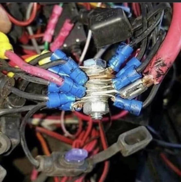
Shudder.....
The only thing missing from that mess is scotchlocks....
QUOTE(ClayPerrine @ Jan 10 2020, 09:50 AM)
QUOTE(Larmo63 @ Jan 9 2020, 09:01 PM)
Hold my beer.........
Shudder.....
The only thing missing from that mess is scotchlocks....
That looks like my aka turbo car.
Professional.....Perry Kiehl. Engine harness is a thing of beauty.Click to view attachment
Now that you have some good racheting tools and dies, the next think you need to be thoughtful of is the connector itself. The stuff you get at the auto parts store all seem to fail. I go as far as pulling of the plastic sheath, crimp the terminal so I can visually see a good connection and slide back on the sheath.
There are also types of connectors that not only crimp the exposed wire, but they have an extra tang to crimp onto the sheathing - which is more like an OEM type of connection from what I have seen.
McMark posted a long time ago where he gets his terminals and they look to be excellent.
There are also types of connectors that not only crimp the exposed wire, but they have an extra tang to crimp onto the sheathing - which is more like an OEM type of connection from what I have seen.
McMark posted a long time ago where he gets his terminals and they look to be excellent.
QUOTE(TravisNeff @ Jan 10 2020, 03:56 PM)
There are also types of connectors that not only crimp the exposed wire, but they have an extra tang to crimp onto the sheathing - which is more like an OEM type of connection from what I have seen.
McMark posted a long time ago where he gets his terminals and they look to be excellent.
For the previous postings that referenced the need for strain relief, the OEM connectors have built in strain relief as mentioned above. Esentially the lightly rolled end tabs capture the insulation and use that as a means to keep strain off the actual electrical connection.
These are the types of crimp connectors that should be used as noted by previous post.
Click to view attachment
I will also point out that the crimpers the OP posted a picture of are the same ones I use and they are designed to crimp the bare wire and sheath crimps of the OEM style terminals simultaneously using a stepped crimping die.
QUOTE(bbrock @ Jan 11 2020, 11:24 AM)
I will also point out that the crimpers the OP posted a picture of are the same ones I use and they are designed to crimp the bare wire and sheath crimps of the OEM style terminals simultaneously using a stepped crimping die.
I followed your lead @bbrock , very nice to use and way-way-WAY better than how I had been doing it. I am likely going to go back and re-do quite a few connections now.
This is a "lo-fi" version of our main content. To view the full version with more information, formatting and images, please click here.