Quick question regarding the DME relay and fuel pump...
Is it required to power the Fuel Pump off of pin 87b from the DME relay, or can one simply power the DME and Fuel Pump simultaneously, say, from the ignition switch?
Thanks
Full Version: Quick Question regarding 3.6 conversions
I'm using the PMS conversion harness and the fuel pump runs off the DME.
I'd be reluctant to run the fuel pump straight off the ignition switch.

I'd be reluctant to run the fuel pump straight off the ignition switch.
QUOTE(SirAndy @ Jan 4 2021, 02:25 PM) 
I'm using the PMS conversion harness and the fuel pump runs off the DME.
I'd be reluctant to run the fuel pump straight off the ignition switch.
Thank you @SirAndy
Thinking about it further, after the post, I've come to the same conclusion. Working my way through the **questionable** wiring on my ECU, but I think I'm seeing light at the end of the tunnel.
You need at least two standard relays for it to work correctly.
The DME relay is Bosch's substitute for two standard relays. One turns on power to the ECU and the fuel pump relay, and the other is triggered by the ECU to run the fuel pump, injector power, and the O2 sensor. If the ECU doesn't see a pulse from the crank sensor, the Fuel pump relay does not energize, so no fuel and no injector pulse.
If you like, I can draw a diagram of how mine is wired. It works fine, and I used Bosch solid state relays.
Personally, with all the DME relay issues I have seen, I didn't want one on the car. If you are using the stock /4 relay board, you can use the relays for the D-Jet ECU. They are already wired correctly.
Clay
Hi @ClayPerrine - Previous modification got ride of the stock /4 relay board, and a diagram would be really helpful, thank you.
Digging into all this currently after finishing the stock wiring this last weekend and I believe my current setup uses 1x relay to turn on the ECU and DME, though I'll need to confirm as I'm not infront of the car now. DME Pin-87b definitely seems to be powering fuel pump on mine. I'm fine going that route, or another as I have 2x extra relays in the front trunk.
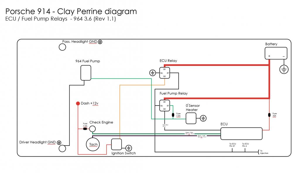
In the interest of clarity, I've begun mapping out the electrical system(s) on my car. Option 1 (shown in Orange) is what I understand to be the original route. Option 2 (shown in Green) is what I was thinking I would do going off of ignition.
Thanks in advance, guys!
Click to view attachment
Digging into all this currently after finishing the stock wiring this last weekend and I believe my current setup uses 1x relay to turn on the ECU and DME, though I'll need to confirm as I'm not infront of the car now. DME Pin-87b definitely seems to be powering fuel pump on mine. I'm fine going that route, or another as I have 2x extra relays in the front trunk.
In the interest of clarity, I've begun mapping out the electrical system(s) on my car. Option 1 (shown in Orange) is what I understand to be the original route. Option 2 (shown in Green) is what I was thinking I would do going off of ignition.
Thanks in advance, guys!
Click to view attachment
Here is a quick and dirty diagram to wire up the ECU and Fuel pump relays. This replaces the DME relay.
Click to view attachment
What is happening here is when you turn the key on, the ignition switch supplies power to the ECU relay coil. The ECU relay closes, and supplies power to the ECU, the injectors, the ignition coil igniters, and other items. It also supplies power to the relay coil for the Fuel Pump relay. When the DME sees a pulse on the crank sensor, it grounds pin 85 on the fuel pump relay, turning on the fuel pump and the O2 sensor heater.
There are other things that also come off pin 87 the ECU relay that are not listed in this diagram. If you refer to the wiring diagram I posted in your build thread, the output from pin 87 on the ECU relay goes to junction point #1 on the wiring diagram.
Hope that helps.
Clay
@ClayPerrine - Very helpful as well as the post on my project thread, can't thank you enough. While I'm sure every 3.6 project is different, this and other information really helps to piece things together.
Do you mind if I replicate this diagram for future reference and post it on here? Sometimes, such is my case, it really helps to know what others did, and the smallest shred of info can open a lot of doors.
For anyone reading this or for any future search items that may come up, I'm also posting a diagram shared various times by @racerx9146 that I found very helpful in regards to pin / wire identification
Click to view attachment
QUOTE(RiqueMar @ Jan 5 2021, 11:45 AM)
@ClayPerrine - Very helpful as well as the post on my project thread, can't thank you enough. While I'm sure every 3.6 project is different, this and other information really helps to piece things together.
Do you mind if I replicate this diagram for future reference and post it on here? Sometimes, such is my case, it really helps to know what others did, and the smallest shred of info can open a lot of doors.
For anyone reading this or for any future search items that may come up, I'm also posting a diagram shared various times by @racerx9146 that I found very helpful in regards to pin / wire identification
Click to view attachment
That is a great diagram. But my experience with DME relay failures made me go with two Bosch solid state relays instead. You can use this diagram, and replace the DME relay with the two in my diagram. Plus, square Bosch relays are available in your FLAPS, DME relays are way more expensive and only available from a specialty Porsche shop or the dealer. You can walk into a local auto parts store and pick up a generic horn relay for under 5 bucks that will work to get you home without a flatbed.
QUOTE(ClayPerrine @ Jan 5 2021, 11:06 AM)
That is a great diagram. But my experience with DME relay failures made me go with two Bosch solid state relays instead. You can use this diagram, and replace the DME relay with the two in my diagram. Plus, square Bosch relays are available in your FLAPS, DME relays are way more expensive and only available from a specialty Porsche shop or the dealer. You can walk into a local auto parts store and pick up a generic horn relay for under 5 bucks that will work to get you home without a flatbed.
I understand that, and it makes sense. Currently, my difficulty is not knowing what is/was done to the engine ECU previously, save for the elimination of the 914-4 relay board, so I'm trying my best to combine all info and find a work through, as the car did work previously.
I figure my best hope right now is to get everything working as it was and proceed from there. Based on the diagram you drew , Clay, I've come up with this and added info from the other diagram as well, please let me know what you think, and again thanks for the help!
Click to view attachment
QUOTE(RiqueMar @ Jan 5 2021, 03:36 PM)
I understand that, and it makes sense. Currently, my difficulty is not knowing what is/was done to the engine ECU previously, save for the elimination of the 914-4 relay board, so I'm trying my best to combine all info and find a work through, as the car did work previously.
I figure my best hope right now is to get everything working as it was and proceed from there. Based on the diagram you drew , Clay, I've come up with this and added info from the other diagram as well, please let me know what you think, and again thanks for the help!
The diagram looks great. It is better than my hand drawing.
Let me know if I can help you in any way.
And Betty says she finally has a diagram on how Clay Perrine works.
QUOTE(ClayPerrine @ Jan 6 2021, 03:39 PM)
The diagram looks great. It is better than my hand drawing.
Let me know if I can help you in any way.
And Betty says she finally has a diagram on how Clay Perrine works.
Good to hear! DM me your email, and I'll send a pdf copy. Will be adding more info as I progress. Main goal is to get the system functioning as it was previously, and then clean up / convert / improve from there. As I dig into different documentations of 3.6 conversions, I've come to the conclusion that 'no two projects are alike'.
Adding to this dialogue, have currently started documenting my setup 'as-is'. So far, this is where I'm at, and mind you, all was functioning. Any and all feedback welcome, trying to get this thing running so I can clean it all up! 
Click to view attachment
Click to view attachment
You have the "constant power" feed to the ECU running through a relay. It needs to be direct to the battery. The ECU actually learns the engine. Every time you disconnect the battery, it loses all of that learning, and has to start over. The constant power feed to the ECU keeps the memory intact.
Clay
Clay
QUOTE(ClayPerrine @ Jan 9 2021, 06:16 PM)
You have the "constant power" feed to the ECU running through a relay. It needs to be direct to the battery. The ECU actually learns the engine. Every time you disconnect the battery, it loses all of that learning, and has to start over. The constant power feed to the ECU keeps the memory intact.
Clay
Just posted and already very helpful, I'll note that and begin making changes like that.
Right now, I'm trying to figure out the leads from the DME '87b'. One of which is cut-clean, and the other that disappears into the harness, believe it to be Green/Black, and lead somewhere on the engine. I previously marked it as 'Coils, but now think it is to one of the sensors.
This is a "lo-fi" version of our main content. To view the full version with more information, formatting and images, please click here.