Help - Search - Members - Calendar
Full Version: PorSTi Project Thread…
914World.com > The 914 Forums > 914World Garage
Pages: 1, 2, 3, 4, 5, 6, 7, 8, 9, 10, 11, 12, 13, 14
McMark
QUOTE
I may not quite understand the question.

Nope, I was confused. I understand now.
Amenson
Lots has happened since my last post.

My wife and I purchased our first house on Friday! Thankfully it is the house that we are currently living in so the move will not be so bad...already done beer.gif Now that we own it the house projects will start ramping up, yet another good reason to get the car on the road in the next 2 weeks.

Click to view attachment

Suby wires touched the car for the first time. Had to make the mount for the main fuse box before the engine went back in. The harness was quickly returned to the basement for further modification.

Click to view attachment

While going through the parts bins I realized that I forgot to install the gaskets for the timing belt covers, so off those came. While I was in the area I helicoiled the alternator/PS bracket bolt that the dealership stripped when I brought the donor car to them for a new power steering pump. headbang.gif

Click to view attachment

Hopefully the last picture of the firewall like this for a while. I went through and tightened everything while I had easy access.

Click to view attachment

...
Amenson
...
A gratuitous glamor shot on the way back home.

Click to view attachment

Home again.

Click to view attachment

Made and mounted the line for the slave cylinder. Can't hook it up because my SnapOn inverted flare took broke. This is the first really crappy tool that I have purchased from them.

Click to view attachment

Shift linkage is in.

Click to view attachment

Click to view attachment

...
Amenson
...
Also installed the drivers seat and shifter. I was going to leave the seat out until the last minute to keep it from getting scuffed up but decided that it would probably be a good idea to give my wife someplace to sit when she is helping me bleed the brakes. Plus it makes the car seem more drivable driving.gif

Click to view attachment

I still have some mechanical stuff to finish up but am going to start spending the majority of the time working on the wiring. Less than 2 weeks until Woodward, must stay focused. wacko.gif

Scott
pktzygt
I'm really jealous. I'm still in the staring at the motor in the car and wondering how to reconnect all the loose vacuum lines and plugs. Then I still need to figure out how to get an intercooler to stay put in there.
Amenson
QUOTE(pktzygt @ Aug 3 2009, 01:27 PM) *

I'm really jealous. I'm still in the staring at the motor in the car and wondering how to reconnect all the loose vacuum lines and plugs. Then I still need to figure out how to get an intercooler to stay put in there.


You would not be jealous if you knew how much time it has taken to get this point.

I would recommend going to the Subaru technical website and download the factory manual for the engine"s donor car. Very useful stuff.

Oh, and it really helps to have the same car that the engine came from in your driveway to look at when you get stuck beer.gif

Keep at it,
Scott
Amenson
Still plugging away.

My new flare tool came in so I finished the clutch plumbing.
Click to view attachment

Figured I should give it a try so I bled all three new hydraulic circuits. Takes a while to fill all those lines but got it done with the help of my wife. The clutch seems to work very well. The brakes are, well...stiff, to put it mildly. The master cylinders are sized for the new calipers, not the ones on there now.

First fluid in the car!!!
Click to view attachment

Looks so sad up on the stands w/o wheels.

Click to view attachment

I also installed all of the intake plumbing clamps. Bought a boatload of T-clamps and it was so tight in places that I had to resort back to regular old hose clamps.

Click to view attachment

And installed the driver's harness. Unfortunatly it might not work very well because I am probably going to run out of adjustment. The belts are made to be installed in normal sedans with a much larger gap between the mounting point and the seat.

Click to view attachment

Did a bunch of other things not picture worthy like install the rubber strip under the fuel cell straps and tighten everything up, ran the soft part of the return line, set all of the steering coupler positions and tightened everything down, and worked on the wiring harness.

Still more to go but the end is in sight.

Scott
Amenson
Today was harness day, and what a day it was.

Apparently this is what I look like after 10, nearly continuous, hours of working on the harness. Not pretty wacko.gif

Click to view attachment

This is what I removed.

Click to view attachment

This is what is left.

Click to view attachment

I can't seem to find the main cruise control switch, rear blinkers, or brake lights. Other than that, everything that I need is there and labled. There are a few things that I have not identified yet. Hopefully get these things figured out first thing tomorrow morning so that I can wrap it up a bit and lay it in the car to see where things will mount and how much I will need to extend parts of the harness to get to the front of the car. I know that the harness in the back could be shortened up a bit but that will be a winter project. Now I just need to do what is necessary to get it running.

Scott
Amenson
Still not running. It seems like the to do list is infinite, just when I think that it is getting shorter I find new things to add. I was really hoping to have it running today. Not going to happen. I did take tomorrow off from work so I should be able to get it to fire tomorrow.

Here is the harness pretty much ready to go for initial fitting.
Click to view attachment

Subaru made the main chunk of the harness in two parts that seperate by a load of connectors. Here is the left half.
Click to view attachment

In the car. The loose wires dangling below the fuse box are the radiator fan and headlight circuits. They will be extended to the front and then wrapped.
Click to view attachment

I decided that in order to reduce the potential bugs, I would start the engine before I start lengthening the harness to the front. This means that all of the switches, sensor, etc will be in the trunk for startup. Once everything is working as expected I will start cutting/splicing.

Finished the top to the coolant filler tank. It was nice to pick up the torch again after staring at wires for 3 days straight.
Click to view attachment

Filled it with trans fluid and oil.
Click to view attachment

Also wrapped the exhaust going under the trans and tidied up/tightened a load of other things. It is going to be very tight getting it ready for next weekend but there is still a real chance. Tomorrow will tell.

Scott
Amenson
Running!!! beer.gif beerchug.gif beer3.gif

https://www.youtube.com/watch?v=kembTjP-4ao

It would have started on the first turn of the key had I remembered that the clutch needs to be pressed. The ecu is not entirly happy and then there is the small matter that everything is still in the trunk. Oh, and based on the valve noise I did not quite get the valve clearances quite right.

Much more to do and not much time before Woodward. I have had it for today, time for bed.

Scott
championgt1
Congrats! Just the fact that it runs has to be a huge success. What a cool project. smilie_pokal.gif
VOX
whoo congratulations!
Zaney
Great Job Scott!!!!
The attention to detail is simply awesome! This thread shows that it can be done!!

(now it is time for a WRX tranny! stirthepot.gif )

Good luck for the Cruise!


Nate smilie_pokal.gif
Amenson
QUOTE(Zaney @ Aug 11 2009, 07:23 AM) *

Great Job Scott!!!!
The attention to detail is simply awesome! This thread shows that it can be done!!

(now it is time for a WRX tranny! stirthepot.gif )

Good luck for the Cruise!


Nate smilie_pokal.gif


Thanks the positive feedback guys beerchug.gif The accomplishment feels a little better today after a good night sleep. I was a bit exhausted and overwhelmed by the thought of the work required over the next few days to enjoy the moment.

Just ordered an AccessPort to help work through debug...and no, I will not change to the stage 2 map. happy11.gif

I will go through a couple 901's before I switch to a WRX tranny, hopefully by then someone will have a really nice shift linkage worked out.

Cheers,
Scott
charliew
Nice work, I'm sure the wiring is tough. Disabling the cells will be a trick. My son's subaru mag says that subaru now has a 6 spd the same size as a 5 spd although I don't know what ft lbs it will handle or if it will convert to the front wd like the 5 spd. They also have a cv tranny but it's not in the turbo cars.

Bummer about the valve lash though.

This winter you might want to check out romraider for your tuning although the drive by wire makes it really complicated.
roadster fan
smilie_pokal.gif Keep it up, it will be drivable in no time. Awesome!

Jim
Amenson
About time for another update. I have spent the last couple of weeks trying to find a reason not to open the engine up again. Checked the valve clearance...3 times, all ok. Compression check, fine. Leakdown...better than perfect. Fire up the engine, still clacking. WTF. Finally decided to open her up.

Where did all of this crap come from?
Click to view attachment

Oh, from here.
Click to view attachment

What is wrong in there?
Click to view attachment

Nothing obvious here.
Click to view attachment

Is this one straight?
Click to view attachment

A spin in the drill says yes.

...

Amenson
...

Six of the first six show straight as well. I am starting to get concerned that I my prognosis of bent valves was incorrect. The last two did not disappoint. This is not an optical illusion.

Click to view attachment

A few calls to the regional Subaru dealerships and I have 2 new valves and some gaskets. Time to put it back together...it really looks pitiful.

Click to view attachment

Valves are back in.

Click to view attachment

Put it it back together.

Click to view attachment

...

Amenson
...

Starting to look like an engine again.

Click to view attachment

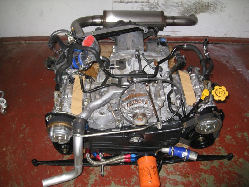
Button it up and stick it in.

Click to view attachment

Home again.

Click to view attachment

I will connect and start it up tomorrow. Man I hope that it is ok now.

Scott
Amenson
QUOTE(Amenson @ Aug 29 2009, 07:57 PM) *


I will connect and start it up tomorrow. Man I hope that it is ok now.


Back in business. The only noise it is making now is the sweet, sweet music of a boosted flat 4.aktion035.gif

Scott
charliew
When did the valves get bent? If they touched the piston there is a chance the rod inserts got mashed. I guess only time will tell at this point. You can check for bent valves by putting some naptha or mineral spirits in the combustion chamber with the head setting level, if it doesn't leak past the valves they are good. How can a bent valve pass the leakdown test? Also a bent valve would cause more bucket clearance than normal because the valve is not completely on the seat.

It's great that it is now quiet.
Amenson
QUOTE(charliew @ Aug 30 2009, 03:39 PM) *

When did the valves get bent? If they touched the piston there is a chance the rod inserts got mashed. I guess only time will tell at this point. You can check for bent valves by putting some naptha or mineral spirits in the combustion chamber with the head setting level, if it doesn't leak past the valves they are good. How can a bent valve pass the leakdown test? Also a bent valve would cause more bucket clearance than normal because the valve is not completely on the seat.

The valves probably got tweaked in the accident or I could have twisted the cam when I was not supposed to when I was reassembling the engine for the first time.

The valves would seat fine. They were bent just enough to come into the seat out of alignment and then snap into place...noisily. With the valve springs out I could get them into the seat with only a very small amount of force with my hand. So, it is possible to have good leakdown and valve clearance readings with a bent valve. I would assume that my engine would have passed your mineral spirits test as well.

I learned many valuable lessons with this fiasco. slap.gif

Scott
budman5201
Hey Scott,
My engine was noisey too when i first started it up. I think mine was sitting in a japanese junkyard for years before i got my hands on it. Not until about and hour running and a quick first oil change did it quiet down. Oh yeah by the way, the more on tune my engine got (aftermarket computer) the quieter it got. Purrs likes yours does now.

Now if it wasnt for that pesky A/C compressor thats going out it'd be quiet again....Next item to fix!
charliew
The early tt dohc motors (96) had hydraulic lifters and they are notorious about being gummy and noisy. Sometimes they need to be removed and cleaned to get to run quiet.
Amenson
It had been a while since I have had a sense of accomplishment so I decided to make the front filler tank today.

I was planning to order all of the fittings and material and making one from scratch until I found this one at Speedway Motors for nearly the same price as the parts I needed. Of course it did not come pre-cut.
Click to view attachment

Down to size:
Click to view attachment

welder.gif
Click to view attachment

Installed, forgot to order the barb fittings so I can not hook it up yet.

Click to view attachment

I think that I will install the axles next and then start pulling more wires.

Scott
Zaney
Scott,

We are Jonesing for an UPDATE icon_bump.gif

Hope all is well!

Nate
Amenson
QUOTE(Zaney @ Feb 18 2010, 08:35 PM) *

Scott,

We are Jonesing for an UPDATE icon_bump.gif

Hope all is well!

Nate


All is well, although I have been slacking on the car a bit...sort of. I have taken care of a load of piddly uninteresting things. Also finished the plumbing for the radiator expansion tank which really helped purge the air from the cooling system. I can now idle the car indefinitely w/o the temperature threatening to leave the normal range without fans.

Click to view attachment

Over Thanksgiving my father and I installed the front air dam. I am thoroughly unimpressed with the fit of this part. Somewhere on the passenger side it is over 1/2" short. Not sure what I am going to do about it. I am really not in the mood to cut it apart and glass it back together but it bothers me every time I look at the car.

Click to view attachment

...

Amenson
My parents bought us a new heater for the garage as a house warming present! 60,000 btu...much nicer to work in the garage now!

Click to view attachment

While I was winter test for 17 days earlier this month I decided to modify the aftermarket electronic spedo sender that attaches to the angle drive so that I could get rid of the angle drive.

Unfortunately I did not take a picture of the part that I made but essentially I remade the brass piece on the right so that I could use the bolt confused24.gif from the angle drive. It is pressed into the housing and the bushing is pressed into it.

Click to view attachment

Finished product with extra parts:

Click to view attachment

Guts:
Click to view attachment

Installed:

Click to view attachment

I made a detailed 3D drawing in Google Sketchup if anybody is interested in doing this to their sender.

Scott
Amenson
Here is the drawing of the bushing:

Click to view attachment


Scott
fat73
QUOTE(Amenson @ Feb 24 2010, 07:11 AM) *

Here is the drawing of the bushing:

Click to view attachment


Scott

The talent on this forum continues to amaze me. Awesome work.
Ed
GS Guy
That's a pretty trick modification to the electronic speedo adapter Scott! I'm going to have to look into doing that to mine. The angle drive serves no real purpose with the electronic sensor, except to adapt it to the trans!

It looks like you cannibalized some parts from the angle drive - obviously the nut, but what else? Sounds like some internal portion that presses into your custom bushing?

Material of the new bushing? What kind of press fits did you use - couple of thousandths?

Is the end product just the 3 new parts added to the sensor housing - the new bushing, piece pressed into the inside and nut on the outside - all this simply pressed into the sensor housing?

I like it!

Jeff
Amenson
QUOTE(GS Guy @ Feb 24 2010, 05:39 PM) *

That's a pretty trick modification to the electronic speedo adapter Scott! I'm going to have to look into doing that to mine. The angle drive serves no real purpose with the electronic sensor, except to adapt it to the trans!

It looks like you cannibalized some parts from the angle drive - obviously the nut, but what else? Sounds like some internal portion that presses into your custom bushing?

Material of the new bushing? What kind of press fits did you use - couple of thousandths?

Is the end product just the 3 new parts added to the sensor housing - the new bushing, piece pressed into the inside and nut on the outside - all this simply pressed into the sensor housing?

I like it!

Jeff


I only used the nut from the angle drive. The piece in the drawing is the only part that I made. The original was brass but I did not have any in the shop at work so I used aluminum. I reused the pressed in brass bushing from the original speedo piece.

The press fits were ~3-4 thou...a bit tight but matched the original parts. The brass bushing presses into the aluminum piece that I made and that presses into the speedo housing. If you want the Sketchup, file let me know and I can email it to you.

Oh, I had to drill out the rivets that hold it together. I replaced them with 3x20 mm hardware.

Scott

Amenson
Well, it is time to dig back into the wiring harness. I started by troubleshooting the only non-functioning part of the electrical system...the alternator. Of course I assumed that I messed up something in the initial harness modification so I spent much longer than normal coming to accept the reality that the alternator is dead. In order to pull the alternator the intercooler had to come out and in order to remove the intercooler the rear trunk had to come off.

Click to view attachment

With that resolved I started in on the wiring. The task is to separate the stuff that needs to be in the dashboard area and the stuff that does not. When I first started back on the wiring I had the distinct feeling of being overwhelmed again. After an hour or so I regained my familiarity with the schematic and it was full steam ahead.

Click to view attachment

Click to view attachment

A few more long days like this and I may be able to start it from the driver's seat finally!

Scott
GS Guy
QUOTE(Amenson @ Feb 24 2010, 10:09 PM) *

I only used the nut from the angle drive. The piece in the drawing is the only part that I made. The original was brass but I did not have any in the shop at work so I used aluminum. I reused the pressed in brass bushing from the original speedo piece.

The press fits were ~3-4 thou...a bit tight but matched the original parts. The brass bushing presses into the aluminum piece that I made and that presses into the speedo housing. If you want the Sketchup, file let me know and I can email it to you.

Oh, I had to drill out the rivets that hold it together. I replaced them with 3x20 mm hardware.

Scott


Hey Scott - I completed the same modification to my speedo sensor yesterday and it seems to work perfectly for mechanical fit. The only thing I found I needed beyond your description was running a 1/4" reamer through both rotor bushings while the unit was assembled (without the rotor installed) to correct a very slight mis-alignment between top and bottom bushings. I was getting some stiffness in turning the rotor after assembly, kissing it with the reamer cleaned it up perfectly.

Now about that spaghetti... sure that engine doesn't have some Italian blood? biggrin.gif

Jeff
ruby914
Scott,
Nice work.
Seems you are taking a break from all the wires.
I know the feeling.
I saw what you were doing with your steering column and was inspired to follow. I will try to incorporate the instrument cluster and fabricate a new dash around it also.
I have all I need but the WRX steering wheel. I already started cutting but I am thinking it is still too long?
I see you cut it down "two more inches" so I know you have been there.
I don't have the Subaru wheel yet so I wonder if the depth between the grip and shaft is shorter on the Subaru wheel?
I measure about 7.5" outboard and 8.5" inboard from the stock 914 wheel to flat dash face. What did you finally come up with, from the dash, with the Subaru wheel?

Amenson
QUOTE(ruby914 @ Aug 3 2010, 07:55 AM) *

Scott,
Nice work.
Seems you are taking a break from all the wires.
I know the feeling.
I saw what you were doing with your steering column and was inspired to follow. I will try to incorporate the instrument cluster and fabricate a new dash around it also.
I have all I need but the WRX steering wheel. I already started cutting but I am thinking it is still too long?
I see you cut it down "two more inches" so I know you have been there.
I don't have the Subaru wheel yet so I wonder if the depth between the grip and shaft is shorter on the Subaru wheel?
I measure about 7.5" outboard and 8.5" inboard from the stock 914 wheel to flat dash face. What did you finally come up with, from the dash, with the Subaru wheel?


Ruby914,
Thanks for the feedback. Glad you could find some of my experiences useful headbang.gif. Although, the steering wheel adaptation is one area where my current implementation can be improved.

Currently the steering wheel sticks too far away from the dash. I do not have the stock IC installed so I measured from the back of the steering wheel to the vertical face of the dash along the steering column and the wheel is 10" away. This will be difficult to change and there is not so much room if you intend to use the Subaru plastic column cover. For me it is not much of a problem because I am short and made my pedal box position adjustable. I will have to recline my seat yet to get the perfect seating position.

There is also a problem on the back side. The shaft sticks out a bit too far and it required that I shorten parts of the intermediate shaft so that I could slide the knuckles as far over the splines as possible to avoid exceeding the max working angle of the knuckles. Before I did this I had a bit of binding. I would recommend shortening the back side even more than I did so that the shaft ends up in the same place as stock. This will require a modified/different mounting method.

Eventually I will do it again, maybe this winter. Hopefully you can refine the design so that I can copy you!

As for the wires...I have actually started to revisit them again the past couple of weeks. I have not posted any pictures because a bundle of wires looks like a bundle of wires no matter how much time I put into them. I did have a bit of a breakthrough...maybe more accurately, a reason to redo a whold bunch of work.

After much measuring and many mental iterations of wire routing, I think that I have figured out a very clean way to run the wires with a minimal amount of harness stretching. In some areas I may eventually get to shorten a few sections. If I move the main fuse box to the front where the old master cylinder reservoir was located and move the ECU to the center tunnel just in front of the rear access panel, I should be able to mount the secondary fuse box and relays under the dash or mabye under the front hood someplace. This will put all of the connectors for the Instrument cluster, switches, IG, ...etc in the proper place.

In order to do this though, it required pulling the pins for most of the wires so that I can separate the right and left engine bundles from each other and from the wires that go to the dash area. This is a very tedious process of getting the pins out of the connectors, fishing the wires out of the bundle running it back with the other wires for the same location and then getting the pin back in the correct place in the original connector. So far there have been ~10 wires that take short cuts that I have had to mark, cut and eventually extend. I have a few more hours of reorganizing before I can lay the harness in the car to confirm if my plan will work. Stay tuned.

Cheers,
Scott
ruby914


Scott,
I did some more cutting as seen in this photo and cut 1/4" off of each end of the intermediate shaft.
I drilled a new hole about 7/8' AFT of the original mount hole so all this gained me an extra 7/8", if I don't get a bind.
I also trimmed the cover until I got to where the back cover snaps together. This just fit but it may be better to trim the dash so the cover fits inside. I may still need to do that.
Were you trying to keep the tilt feature?
I really want to keep that but I think I will have to weld on a bar to mock a longer steering column and have that pivot around the first U-joints.
That will be a hard fit but other wise it seems to rotate too easy when locked and I think it will bind at any other pivot location.

I put my ECU behind the passenger seat you can see how that fit here http://z8.invisionfree.com/ClubNARP/index.php?showtopic=5431
Amenson
QUOTE(ruby914 @ Aug 12 2010, 08:29 AM) *

Scott,
I did some more cutting as seen in this photo and cut 1/4" off of each end of the intermediate shaft.
I drilled a new hole about 7/8' AFT of the original mount hole so all this gained me an extra 7/8", if I don't get a bind.
I also trimmed the cover until I got to where the back cover snaps together. This just fit but it may be better to trim the dash so the cover fits inside. I may still need to do that.
Were you trying to keep the tilt feature?
I really want to keep that but I think I will have to weld on a bar to mock a longer steering column and have that pivot around the first U-joints.
That will be a hard fit but other wise it seems to rotate too easy when locked and I think it will bind at any other pivot location.

I put my ECU behind the passenger seat you can see how that fit here http://z8.invisionfree.com/ClubNARP/index.php?showtopic=5431


Ruby914,
I checked out your thread on ClubNARP, amazing composite work. If you work out a new dash that fits the Suby cluster I would likely be interested in a copy.

I did keep my steering column adjustable, if for no other reason that I could not decide where to put it permanently. There is a picture of my mount back a few pages.

I moved the harness back into the car to see how everything fits. Pretty much the only place where I can get the passenger side of the engine connected at the same time as the dash stuff is with the ECU on the center tunnel. I should be able to modify the stock between the seat storage box to hide it and still have some storage.
Click to view attachment

I mounted the main fuse box down where I have the battery.

Click to view attachment

The secondary fuse box and relays seems to fit where the stock fuse box was. Although I have not figured out how to mount it. Maybe I can get that done yet this morning.

Cheers,
Scott
ruby914
Scott,
Thanks for the compliments on the dash.
Actually, you were one of the first I thought would possibly need the dash.
But when I saw you were working on a custom, printed circuit board, LED instrument panel, I figured you would not need it.
I don't think I would be going this direction if I had not read your thread and I would be happy to help your project come together.
With your interest, I have swayed back to a more robust mold and will see what I can do to accommodate you.
I will get an e-mail back to you shortly.
ruby914
Scott,
I checked the resistance between the WRX and 914 fuel sending units and added a 250 ohm resister in parallel from the green to brown 914 wires.
The resisters were from radio shack and only 1/2 W so I don't know what it should be or if that will last. This seems to work using the 914 sender unit for now.
You are a lot more knowledgeable than i with electronics, if you see any problem let me know.
I got my blinkers, and high beam lights working off the Suby column switch also but I have no 2002 Daytime running lights resister.
So I still have no low beams.
PN. 84057FE010 $69 - $45 is the cheapest I have found. I have been hunting around for the ohms and wattage of this part if you have an 02 maybe you could check yours for me?
I also tend to wonder if the 914 lights would need a different ohms value?

Edit:
I got high and low working.
I still don't understand the DRLs 100% but it is looking like I don't need the resister or any part of this circut.
Root_Werks
icon8.gif

Oh man, I stared too long at all those wires. lol-2.gif

Seriously, amazing work! I couldn't even begin to think I could keep track of all that. What a cool project!

smilie_pokal.gif
Amenson
QUOTE(ruby914 @ Sep 23 2010, 08:06 AM) *

Scott,
I checked the resistance between the WRX and 914 fuel sending units and added a 250 ohm resister in parallel from the green to brown 914 wires.
The resisters were from radio shack and only 1/2 W so I don't know what it should be or if that will last. This seems to work using the 914 sender unit for now.
You are a lot more knowledgeable than i with electronics, if you see any problem let me know.
I got my blinkers, and high beam lights working off the Suby column switch also but I have no 2002 Daytime running lights resister.
So I still have no low beams.
PN. 84057FE010 $69 - $45 is the cheapest I have found. I have been hunting around for the ohms and wattage of this part if you have an 02 maybe you could check yours for me?
I also tend to wonder if the 914 lights would need a different ohms value?

Edit:
I got high and low working.
I still don't understand the DRLs 100% but it is looking like I don't need the resister or any part of this circut.

Mike,
Good to hear that you found a solution for the fuel sending unit. The sender in my tank has the opposite resistance to the suby unit. Not sure what to do with that yet. confused24.gif

My harness is out of an 05, I do not have running lights. Can't help with your issue but resistors are pretty cheap if you order one from someplace like Digikey.
One thing that I have been thinking about is how to get the headlights to flip up from the Suby column. The 914 switch has a few extra contacts to work with the headlight motor. I am pretty sure that I can work it out with a relay, maybe two, but have not drawn the circuit yet. What did you come up with?

Cheers,
Scott
Amenson
QUOTE(Root_Werks @ Sep 23 2010, 08:09 AM) *

icon8.gif

Oh man, I stared too long at all those wires. lol-2.gif

Seriously, amazing work! I couldn't even begin to think I could keep track of all that. What a cool project!

smilie_pokal.gif

They are all color coded pinch.gif
Amenson
I thought a little bit more about the daytime running lights. Is there a relay or set of contacts that switches the resistor into the headlight circuit for DLR's?

In the end I don't think that it makes much sense having daytime running lights with flip up headlights. Unless you wanted to run your fog lights as DLR's idea.gif

Scott
AZ914
QUOTE(Amenson @ Sep 29 2010, 07:05 PM) *

Unless you wanted to run your fog lights as DLR's idea.gif

Scott


I know a few guys that have their FOGS wired to be hot on ignition (switched on) instead of with the parking lights. They use them for DRLs but you can always turn them off. Works great.
ruby914
I spent all this time and effort to get my low beams working thinking it was the ground that I didn't have the resister for.
I just wanted low beams, didn't even know what DRL's were for. I didn't have the DRL module and found people were taking them out of there cars, so I didn't need one.
Someone told me the resister was to lower the intensity of the lights, I didn't see a need for that.
I connected the DRL solenoid to ground with no resister. lights still didn't work. I was rotating the switch thinking first click was low, 2nd was high.
Finally found that the high beam is push forward and pull. But at this point the ground was not connected?
I looked at the circuit again. Seems I don't need the DRL module, diode and if I remove the DRL solenoid and connect the YG and YR wires that is all that is needed?
I am still not sure what the first rotation of the light switch should do? I am thinking it will operate the headlight motors through the unused DRL solenoid?
Again Scott, your far better with the electronics than I. Am I missing anything?

Quick update: I now have all the outer lights working, the tail / running lights were last. I put a diagram on my build thread at NARP.
Britain Smith
Which remote oil filter kit is this?

IPB Image

-Britain
GS Guy
Looks like Scott's running Canton hardware for the oil system? They make some nice stuff!
Amenson
QUOTE(GS Guy @ Nov 4 2010, 01:35 PM) *

Looks like Scott's running Canton hardware for the oil system? They make some nice stuff!

Yup, they are Canton parts. I think that I ordered them directly from Canton.

Cheers
Scott
Amenson
OK, so I made some decent progress recently, mostly thanks to ruby914. He made me a copy of his Subaru instrument cluster adapted dash. There is a link to his build thread a few posts back and if you have not already visited it, please do. He has made some really nice parts for his car.

So back to the dash, the part is amazing.
Click to view attachment

If you have removed the dash from your car, you will definitely appreciate what I have to say. If not, go out and remove it and then reinstall it before you continue reading.

He built all of the mounting lugs into his part. Yes, all 8 of them.
Click to view attachment

When removing the stock dash I was not sure that it would actually come out because the bolts stick through the vertical and horizontal faces of the sub dash. You have to lift and pull at the same time but there it only moves a short distance before the bolts in the other plane start binding. Anyways, after talking to ruby914 and seeing pictures of his work I was pretty sure that the part would fit but even with his skill I anticipated a bit of wrestling to get it in just because the fit is so stink'n tight. Not the case at all. I put the part in place checked a few holes for alignment, wiggled it a bit and it popped right in place.

I had to do some modifications to the sub dash to get the bottom ears of the instrument cluster to fit but the directions in his build thread made it very straight forward.

Isn't it cool!! first.gif
Click to view attachment

Click to view attachment

I also did quite a bit of very uninteresting stuff. Mostly organizing wires and mounting relays, switches and other random harness components. I am getting closer to being able to take the harness out again to lengthen and reconnect the wires that I have been cutting to get the harness to match the position of the components.

Cheers,
Scott
This is a "lo-fi" version of our main content. To view the full version with more information, formatting and images, please click here.
Invision Power Board © 2001-2024 Invision Power Services, Inc.