Full Version: PorSTi Project Thread…
Thanks Scott.
Finally took the time to remove the STI DOJ's from the axles. They are in really good shape and both fit the LSD!
Click to view attachment
It is amazing how much plunge the joints have. Definitely do not need floating axles with this type of joint.
I started pulling apart my extra suby trans so I took the oportunity while the center diff and other parts where off to weight it. Came in at 105 lbs. Measured a 901 and it is 80 lbs. Both were dry.
I decided to make my own engine cross bar. Considering using 1x1.5" rectangle tubing .120" wall (A513). Any FEA geeks out there want to provide feedback if this will be strong enough? Engine should weigh ~300lbs + a bit for exaust, intake etc.
Still looking for another phone dial or two.
Cheers,
Scott
Do you want the Lotus approach - its to heavy. Weight is not the only stress it has to endure. You have torque and forces induced by engine rotation. The arms become a huge lever. With out putting it through modeling or real world trails its just a guess.
My approach is go stronger, because not knowing your design, means I have to compensate for things beyond my current understanding. I just built my transmission hangers, well they are in mockup and tacked together. I used 1.5" DOM with a 0.125 inch wall. It is most likely over kill, but I had it and well thats the best metal to use, free!!! I ended up using the factory bar from a tail shifter because I had it around, and I bored the bolt holes out for 1/2" bolts, because thats what my Energy Suspension bushings required. It is also most likely over kill. But the engine mounts I picked up where built from 3/8 inch plate. The original ones I was building was 3/16" So I might have been wrong or Small Car, decided they wanted the no pictures of it yet.
But here are my trans hangers. Still need a little fitting, the gap is a little wider than I like. I now know why Ian went with Angle for his trans hangers. Hold it in place, mark, cut, and done. I am a masochist when it comes to working with metal. So much pain for so little pleasure.
Click to view attachment
Click to view attachment
I might be adding the Subaru mount piece to them also, to tie them together. Not needed, but I am thinking of using it for a place to mount a wheel, just in case I need a wheelie bar. In reality, it would be to have a location for a caster to make the engine easier to move about.
My approach is go stronger, because not knowing your design, means I have to compensate for things beyond my current understanding. I just built my transmission hangers, well they are in mockup and tacked together. I used 1.5" DOM with a 0.125 inch wall. It is most likely over kill, but I had it and well thats the best metal to use, free!!! I ended up using the factory bar from a tail shifter because I had it around, and I bored the bolt holes out for 1/2" bolts, because thats what my Energy Suspension bushings required. It is also most likely over kill. But the engine mounts I picked up where built from 3/8 inch plate. The original ones I was building was 3/16" So I might have been wrong or Small Car, decided they wanted the no pictures of it yet.
But here are my trans hangers. Still need a little fitting, the gap is a little wider than I like. I now know why Ian went with Angle for his trans hangers. Hold it in place, mark, cut, and done. I am a masochist when it comes to working with metal. So much pain for so little pleasure.
Click to view attachment
Click to view attachment
I might be adding the Subaru mount piece to them also, to tie them together. Not needed, but I am thinking of using it for a place to mount a wheel, just in case I need a wheelie bar.
In reality, it would be to have a location for a caster to make the engine easier to move about.
QUOTE(914forme @ Feb 9 2015, 05:10 AM) 
Do you want the Lotus approach - its to heavy. Weight is not the only stress it has to endure. You have torque and forces induced by engine rotation. The arms become a huge lever. With out putting it through modeling or real world trails its just a guess.
My approach is go stronger, because not knowing your design, means I have to compensate for things beyond my current understanding.
Still need a little fitting, the gap is a little wider than I like. I now know why Ian went with Angle for his trans hangers. Hold it in place, mark, cut, and done. I am a masochist when it comes to working with metal. So much pain for so little pleasure.
Ya, about those gaps...
 ...
... I see one of the tube mockup thingies in your picture. Does it help?
I am in the same boat. I know that the current bar works but is way beefy. Something lighter will work, just don't want to risk going too light. Luckily somebody
 is providing a tail shift engine bar for me to use or reference for material selection! See you Thursday.
Cheers,
Scott
QUOTE(Amenson @ Feb 9 2015, 09:29 AM)
Ya, about those gaps...
... I see one of the tube mockup thingies in your picture. Does it help?
I am in the same boat. I know that the current bar works but is way beefy. Something lighter will work, just don't want to risk going too light. Luckily somebody
is providing a tail shift engine bar for me to use or reference for material selection! See you Thursday.Cheers,
Scott
Quick answer Nope thus the reason for the gaps!!!!! I hate copying others work, but Ian had the right idea here. Easy to mockup, scribe a line, cut, and well, weld in place. It could also allow the brackets to be smaller. Which would help with leverage on the mounts and other factors. With out going into a bunch of force calculations, it becomes basic physics. Less leverage on a given point if it can be avoided, means less stress on the given point, thus lighter materials can be used.
The issue with the tube tool is keeping it oriented correctly, keeping a constant angle on the tube that matches the finale angle of the production piece. Then be able to get it in there. So I marked a line on the tube. Marked a line on the tool, always keep the two on the marked lines. And still got a gap.
It was closer than if I had done it with a pencil, and just guessing, but not close enough for me to say it was easier. If some one has an easier way, I am open to suggestions. Wood dowels, build a prototype, and then recreate it with metal. I used to do it with a roll of tape, and a sharpie, it works. I have also used a holes, but that works in fitting two tubes. This should have been a simple angle calculation.
 I could weld up a box section, two sides to build the angle then make a pattern and for the other two sides and fill it in.
  That would have been way easier, and could be made just as strong or stronger do to better joints. And I would have been done, when we had a nice day to weld outdid yesterday
 Tube is just so sexy though, I keep going back to it.
If you want "lighter" go with 4130 .095" chromoly.
Have any estimates about the weight of your homebuilt cradle? I'm thinking of using rectangular tubing also because it may be easier to mock up and provide some great torsional rigidity...
Chromoly lol, Im a CSOB, I had the 1.5 in my metal bin.
BTW, I just got done talking plasma CNCs with a co-worker, when we started talking my pipe fitting issue. He said I need this book, it solves all my issues. Pipe Trades Pocket Manual head to Amazon, no new ones in stock, one used. Okay, well, easy enough I am willing to learn.
Then I was walking away and thought oh crap, I know how to do this!!!! 4 hours of frustration would have been ended with a few steps.
Mark the plate with where you want the center of the tubes to land. Drill a hole big enough for you to pull a piece of wire through.
Bolt everything up
Pull the wire down and pass it through both holes. 2 points create a line.
Now I have all the information I need, measure the angles. Duplicate it in tube form.
Am I correct in this thinking?
Still might be easier to do it in flat sections and build the box.
Sorry for the thread hijack here Scott.
I'll start a new thread to see if I get better answers.
BTW, I just got done talking plasma CNCs with a co-worker, when we started talking my pipe fitting issue. He said I need this book, it solves all my issues. Pipe Trades Pocket Manual head to Amazon, no new ones in stock, one used. Okay, well, easy enough I am willing to learn.
Then I was walking away and thought oh crap, I know how to do this!!!!
4 hours of frustration would have been ended with a few steps.Mark the plate with where you want the center of the tubes to land. Drill a hole big enough for you to pull a piece of wire through.
Bolt everything up
Pull the wire down and pass it through both holes. 2 points create a line.
Now I have all the information I need, measure the angles. Duplicate it in tube form.
Am I correct in this thinking?
Still might be easier to do it in flat sections and build the box.
Sorry for the thread hijack here Scott.
I'll start a new thread to see if I get better answers.
QUOTE(914forme @ Feb 9 2015, 07:45 AM)
Sorry for the thread hijack here Scott.
I'll start a new thread to see if I get better answers.
This is a good discussion. I will be doing something similar once I get my engine square with the chassis again.
Moving along with progress, just stockpiling parts now.
I am considering using the AL front 911 cross member when I swap the front struts. I know, it is supposedly less stiff, but...I kind of like it so I may use it. Unfortunately my suspension setup was missing the bracing straps, or whatever they are called.
The think pointed to below:
Click to view attachment
Anybody have a pair that they want to sell or measure so that I can make them?
Thanks,
Scott
Man that is a pretty pan !
Funny your thinking about that.Todays work. LOL

Funny your thinking about that.Todays work. LOL
QUOTE(Amenson @ Feb 18 2015, 11:46 AM)
Moving along with progress, just stockpiling parts now.
I am considering using the AL front 911 cross member when I swap the front struts. I know, it is supposedly less stiff, but...I kind of like it so I may use it. Unfortunately my suspension setup was missing the bracing straps, or whatever they are called.
The think pointed to below:
Click to view attachment
Anybody have a pair that they want to sell or measure so that I can make them?
Thanks,
Scott
I have a set I could measure up for you, have to find them in the bin. I run one, its a heck a lot lighter than stock 914 unit. I never noticed flex, even with DOT-Rs or Slicks. Maybe with wider wheels and tires.

I picked up the smallest Subaru 5mt a starter I could find on Ebay to test the fit. I think that it is similar to the starter that 914forme just posted in his build thread but a different part number. Mine is 23300AA560 and might have come out of an 08 WRX.
It fits w/o cutting...just like Stephen said it would!!!
Click to view attachment
Click to view attachment
I think that I will still need to make a little room for the clutch slave, it is going to be very close.
I picked up a tail shifter engine mount from Stephen and tried it out yesterday. Surprisingly the cast bar is 1/2lb lighter. It also does not fit quite like I was hoping so now I am going to built one. I should be able to make it low profile enough so that it does not hang below the bottom of the floor/oil pan. It really makes me nervous now that the bar is the lowest point.
Cheers,
Scott
I fretted about cutting the trunk as well but I'm glad that I did. The black box in the pic is the cover. I now have direct access to the starter, solenoid and slave cylinder w/o crawling under the car. Very convenient!
Click to view attachment
Click to view attachment
QUOTE(76-914 @ Feb 22 2015, 07:51 AM)
I fretted about cutting the trunk as well but I'm glad that I did. The black box in the pic is the cover. I now have direct access to the starter, solenoid and slave cylinder w/o crawling under the car. Very convenient!
I am definitely not fretting about cutting up the car...if I need to for some purpose. If I can fit something w/o comprising functionality I will and spend the time/money saved improving something elsewhere on the project. Like welding the unnecessary seams in the intercooler plumbing and installing v-band clamps at the IC!
It was above freezing today (34F) so I thought that I would tinker in the garage for a bit. Started cleaning up the 911 front suspension and got stuck trying to remove the dust cap. Didn't have a 2" exaust clamp so I switched over to the engine cross bar. Figured that I would just confirm my measurements and start marking up the parts to cut. 3 hours later and was somehow pretty much finished.
Click to view attachment
Click to view attachment
Need to finish welding it, size the holes, radius the edges and paint it.
Can't wait to get rid of the huge cast piece.
Cheers,
Scott
Click to view attachment
Click to view attachment
Need to finish welding it, size the holes, radius the edges and paint it.
Can't wait to get rid of the huge cast piece.
Cheers,
Scott
I don't recognize that part since you removed all the saw dust.  Nice job on the cross bar.
Nice job on the cross bar.
Specs on the bar? Looks to be 2x2x1/4 with 3/8ths ends? Nice work!
QUOTE(914forme @ Mar 2 2015, 06:23 PM)
I don't recognize that part since you removed all the saw dust.
Nice job on the cross bar. Everything that might go on the car gets a quick swim in the parts cleaner!
QUOTE(mgp4591 @ Mar 2 2015, 07:06 PM)
Specs on the bar? Looks to be 2x2x1.4 with 3/8ths ends? Nice work!
Bar is 1"x1.5", 0.120" wall. The end material material is 3/8 and is welded to the bottom thickness of the bar for a total cantilevered thickness of 0.495". This should swap in for the current bar and keep the engine at the same height. I am going to weld the bar to the engine mount and add some gussets to provide a little extra margin against bending.
Cheers,
Scott
QUOTE(Amenson @ Mar 3 2015, 07:37 AM)
QUOTE(914forme @ Mar 2 2015, 06:23 PM)
I don't recognize that part since you removed all the saw dust.
Nice job on the cross bar. Everything that might go on the car gets a quick swim in the parts cleaner!
QUOTE(mgp4591 @ Mar 2 2015, 07:06 PM)
Specs on the bar? Looks to be 2x2x1.4 with 3/8ths ends? Nice work!
Bar is 1"x1.5", 0.120" wall. The end material material is 3/8 and is welded to the bottom thickness of the bar for a total cantilevered thickness of 0.495". This should swap in for the current bar and keep the engine at the same height. I am going to weld the bar to the engine mount and add some gussets to provide a little extra margin against bending.
Cheers,
Scott
That works and should be plenty strong. Looking forward to your progress!
Could not wait until the weekend to finish the bar...didn't hurt that it was over 40F in the garage. Heat wave. 
New bar with the old bar.
Click to view attachment
Should not be able to break this setup.
Click to view attachment
It holds the engine up!!
Click to view attachment
Should be able to put in a full day on Sunday to finish the engine and trans mounts.
Cheers,
Scott
New bar with the old bar.
Click to view attachment
Should not be able to break this setup.
Click to view attachment
It holds the engine up!!
Click to view attachment
Should be able to put in a full day on Sunday to finish the engine and trans mounts.
Cheers,
Scott
I was cleaning the 911 5-lug front suspension and pulled the A calipers...I knew they were going to be heavy but damn, it was ridiculous. This will not do.
I have had a set of billet dynalite style calipers in a bin forever. I dug them out and started drawing up adapters. Did a search online and found some cheap weld brackets from Jegs that have half of the work done already.
Click to view attachment
I laid out the strut side holes, now I just need to drill them and cut off the rest...hope my math was right! I will need some spacers to center the caliper on the rotor but I think that it is less than 5mm.
As an added bonus, I sized the master cylinder for these calipers so the pedal feel should soften up a bit...it is a bit stiff now.
Cheers,
Scott
Had a buddy over today and we swapped in the 911 front suspension. Went in no problem. Also finished the plate for the new calipers, still need to add a spacer but it seems to fit well.
Click to view attachment
Click to view attachment
I did notice that the strut insert retaining nuts to not properly center the strut. I think that I have the stock nut with KYB (they came with the car) inserts.
Is this the stock nut?
Click to view attachment
I also fussed around with the engine mount. It is deflecting a tiny bit so I am going to run a reinforcing rib down the top.
It is coming together but still quite a bit to do before the roads are salt free!
Oh, anybody want a set of stock front struts? They have BMW calipers with Hawk HP+ pads, fresh rotors and bearings. Trade for a nice 6 pack in person.
Cheers,
Scott
Click to view attachment
Click to view attachment
I did notice that the strut insert retaining nuts to not properly center the strut. I think that I have the stock nut with KYB (they came with the car) inserts.
Is this the stock nut?
Click to view attachment
I also fussed around with the engine mount. It is deflecting a tiny bit so I am going to run a reinforcing rib down the top.
It is coming together but still quite a bit to do before the roads are salt free!
Oh, anybody want a set of stock front struts? They have BMW calipers with Hawk HP+ pads, fresh rotors and bearings. Trade for a nice 6 pack in person.
Cheers,
Scott
Finally after hours in the garage I have some results to share. I fit the reinforcing ribs to the engine cross bar.
Click to view attachment
In order to maximize the height I had a load of clearancing to do for the perfect fit. Also notice the sandblasted ends of the engine side brackets. I cut the previous bracing out of the mount and prepped it to be welded to the new crossbar.
Click to view attachment
Mounts on the transmission came together also. Ready to be welded to the upper plates.
Click to view attachment
Virtually no gap, these should be a treat to weld.
Click to view attachment
And they were.
Click to view attachment
Look ma...no ratchet strap!
Click to view attachment
Also had the phone dials stripped and powder coated. The tires get swapped over tomorrow. Yes, the Fuchs will be available then also
Click to view attachment
Click to view attachment
In order to maximize the height I had a load of clearancing to do for the perfect fit. Also notice the sandblasted ends of the engine side brackets. I cut the previous bracing out of the mount and prepped it to be welded to the new crossbar.
Click to view attachment
Mounts on the transmission came together also. Ready to be welded to the upper plates.
Click to view attachment
Virtually no gap, these should be a treat to weld.
Click to view attachment
And they were.
Click to view attachment
Look ma...no ratchet strap!
Click to view attachment
Also had the phone dials stripped and powder coated. The tires get swapped over tomorrow. Yes, the Fuchs will be available then also
Click to view attachment
Finally finished the engine mount today. Had to use the torch twice to straighten it after welding.
Click to view attachment
Drivetrain is fully supported. Nothing from Porsche exists except the mounting holes in the chassis
Click to view attachment
Now I can drop the drivetrain and install the LSD!
Cheers,
Scott
Click to view attachment
Drivetrain is fully supported. Nothing from Porsche exists except the mounting holes in the chassis
Click to view attachment
Now I can drop the drivetrain and install the LSD!
Cheers,
Scott
Nice progress
A very nice build. 
http://www.performanceforums.com/forums/sh...EJ25-subi-setup
Nice trick to keep the heads on.Drydeck the block to keep the sleeves in place.First time seeing it done to the Subaru blocks,an elegant touch is the matching pockets.Good work.
http://www.performanceforums.com/forums/sh...EJ25-subi-setup
Nice trick to keep the heads on.Drydeck the block to keep the sleeves in place.First time seeing it done to the Subaru blocks,an elegant touch is the matching pockets.Good work.
Time to get serious on progress....HRPT is at the beginning of June and I want to drive the car all May to may sure that it is robust.
Pulled the engine trans and opened the trans to install the LSD and subaspool. Spent hours cleaning the case sealant and leftovers from the exploded center diff. Fortunately the gears and bearings look mint.
Click to view attachment
Got the gearbox back together, backlash set and went to install the o-rings in the bearing carriers. Got a little tight screwing it back in, must be a dry spot grabbing the o-ring...nope stuck. Will not move. Pulled the gearbox back apart and applied heat, will not move. Made a special tool, will not move. Pull the blade from the hacksaw and manually, very carefully, cut the carrier out of the case.
Click to view attachment
Pulled the carriers out of the spare gearbox, ordered a load of new seals and put it back together...again. Finally ready to go back in.
Click to view attachment
The engine trolly is set up for the 901 transmission and the suby trans does not sit level on it. Made for a bit of excitement getting it out, the engine slid off the dolly and wedged against the firewall...no harm no faul. Getting it back in was less eventful but inefficient enough that I will remake or modify the trolly before dropping it again.
Got it back in so that I can mock up the axles. This configuration may hold 1 ft/lb!
Click to view attachment
With the suspension at full droop I left .5" of clearance to remove the axle. Should give some clearance for toe adjustments and the DOJ has some remaining travel:
Click to view attachment
Big outer CV's look very happy!
Click to view attachment
Still a load of stuff to do and the engine needs to come back out to do much of it but the axles were the last of the parts to order. With a solid weekend next week I should be able to start it again....hopefully.
Cheers,
Scott
Looking great Scott! I like the no cradle. Looks very clean & less to work around for the exhaust. Great job 
Wow that looks great, make me want to redo my setup. I really like the calipers.
Banged out some big projects this weekend.
Rerouted the header around the new trans and DOJ's. The exhaust get's a bit close to the boot on the passenger side, special measures will need to be taken to keep it alive.
Click to view attachment
Welding is so much fun with no gaps, some of the joints were so tight I was able to fusion weld them (no filler)!
Click to view attachment
Also hacked the post turbo exhaust to the bare minimum and installed a v-band joint...
Click to view attachment
...so the rest of it can be done in aluminum. Simplify and add lightness.
Click to view attachment
Next on the list were the pesky silicon/clamp joints on the IC plumbing.
Click to view attachment
Gone...took a lot of cutting.
Click to view attachment
Also made clearance for the clutch fork.
Click to view attachment
Ran out of argon after tacking the IC tubing so I had to use the mig. Man do I hate grinding welds.
Total package, see if you can pick out all of the other little modifications.
Click to view attachment
Cheers,
Scott
Do you know what your pre &/or post intercooler air temps are ??
QUOTE(barrym @ May 5 2015, 02:42 AM)
Do you know what your pre &/or post intercooler air temps are ??
Generally at standstill it heat soaks quite a bit but cools down quickly while moving. I have considered installing the stock STI IC water sprayer, which Subaru probably installed for this exact reason.
I found a few data logs on my work laptop and the highest Intake Temp was 47C although I think that I have some other data with higher values.
It turns out that the axles I had made are too short. During testing tonight I pulled the DOJ apart.
I need to have another set made but am out of 911 axles. If anybody has a pair that they would be willing to ship ASAP to Dutchman Motorsports I could use a logistical miracle in order to make Power Tour this weekend.
Send me a PM if you have something.
Scott
I need to have another set made but am out of 911 axles. If anybody has a pair that they would be willing to ship ASAP to Dutchman Motorsports I could use a logistical miracle in order to make Power Tour this weekend.
Send me a PM if you have something.
Scott
Why not machine some spacers and run loger bolts? How much shorter are we talking??
QUOTE(Andyrew @ Jun 3 2015, 04:46 PM)
Why not machine some spacers and run loger bolts? How much shorter are we talking??
I am not sure how much length I really need but spacers are a great idea. Not sure why I did not think of that, I was looking at these when I ordered my CV Boots.
Spacers
They even come with longer bolts!
Probably not good enough for full power but might allow me to limp trough the event.
Thanks!!!!
Still looking for axles to modify.
Cheers,
Scott
Those are actually pretty cool! Gonna save that link for later...
I run one of these spacers on my 6 speed. I implanted magnets to use with my speed sensor.
All right, Bruce (BDStone) is coming through with a set of axles and beyond excellent customer service to get them to Dutchman Motorsports tomorrow. 
Dutchman has agreed to make them a priority in the shop when they arrive and seem to be able to turn them around in a day. Then it is a simple overnight Saturday delivery to me and I am back in business.
The plan for the axles is to make them as long as possible so that they don't bind when level. It will require dropping the back of the control arm to install them but, I am not going through this BS again.
I have done a ton of stuff since my last post, some of it I am particularly proud of and some of it might be useful to others. Will make an update after Power Tour...and probably have a garage sale to pay for the expedited shipping.
Cheers,
Scott
QUOTE(Amenson @ Jun 4 2015, 11:22 AM)
All right, Bruce (BDStone) is coming through with a set of axles and beyond excellent customer service to get them to Dutchman Motorsports tomorrow.
Dutchman has agreed to make them a priority in the shop when they arrive and seem to be able to turn them around in a day. Then it is a simple overnight Saturday delivery to me and I am back in business.
The plan for the axles is to make them as long as possible so that they don't bind when level. It will require dropping the back of the control arm to install them but, I am not going through this BS again.
I have done a ton of stuff since my last post, some of it I am particularly proud of and some of it might be useful to others. Will make an update after Power Tour...and probably have a garage sale to pay for the expedited shipping.
Cheers,
Scott
Hi Scott,
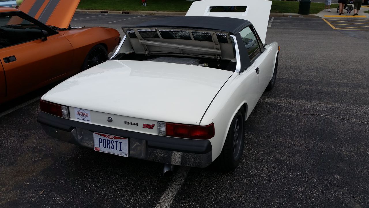
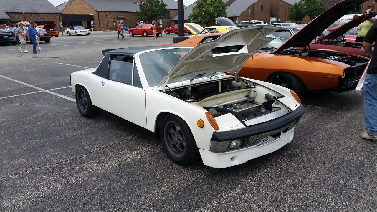
I just signed up on this board to tell you that I think your car is amazing!
I saw it at Parkland College, in Champaign, IL during the Power Tour. Your car caught me as soon as I saw the license plate and of course the STi badging. I have a "lightly modded, never tracked...ah.. who am i kidding....
2005 Subaru WRX STi so it was I thought it was really neat and liked the attention to detail. I was hoping to tell you this in person but I decided to move on to check out the rest of the 4000+ cars before the storms rolled in.Very cool car man!
(I hope you don't mind me posting/sharing a few pictures I snapped of it with my buddies. If so, let me know and i'll take them down. I'll post them here first)
Very nice!
Hello there Mr. Snail. The old Familiar
Very Clean and well done!
Just to show you my car during heavy braking in autocross.
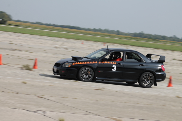
You probably won't see this until after the Power Tour so I hope everything went well, and you made it safely home.
Thanks for bringing the car out, it was awesome!
-Eric
^Eric, great action shot of the Subaru braking hard!
As for the 914, I love those wheels in that color, not too dark or glossy!
Very inspirational build, I must stop viewing it,,,,hahaha
As for the 914, I love those wheels in that color, not too dark or glossy!
Very inspirational build, I must stop viewing it,,,,hahaha
Hi Eric,
Thank you for the very kind words and even more than that, making the effort to find the car on the internets and then signing up to the forum to share them. Now that you are here you should check out the other awesome Suby builds and start planning your own, you already have the same engine donor car that I started with.
Post all of the pictures that you want...especially the one of the rear. Dutchman Motorsports deserves some extra exposure for the job they did turning my axles around in a day. If you post it on Facebook, please tag them.
Thanks,
Scott
Glad you made the tour, uneventful I hope!! Car wise that is.
How is the hood opening doing for your temps, and is that the only opening you have for exit? Still at the point I am pondering the cooling, like everyone else does. But your system seems to work, and well I don't think you just drive around at idle in fear that it will over heat.
How is the hood opening doing for your temps, and is that the only opening you have for exit? Still at the point I am pondering the cooling, like everyone else does. But your system seems to work, and well I don't think you just drive around at idle in fear that it will over heat.
QUOTE(914forme @ Jun 13 2015, 05:17 AM)
Glad you made the tour, uneventful I hope!! Car wise that is.
How is the hood opening doing for your temps, and is that the only opening you have for exit? Still at the point I am pondering the cooling, like everyone else does. But your system seems to work, and well I don't think you just drive around at idle in fear that it will over heat.
The hood opening is the only place air exits the radiator. Cooling is rock solid no matter what I do. Fans do not turn on unless I am stationary for a while even in super hot weather after beating on it. Most mornings on my 15 minute drive to work with several stop lights the fans don't turn all at all. The rather large Ron Davis radiator probably has something to do with it.
Cheers,
Scott
I've just finished reading 25 pages of a really well thought out and beautifully executed build. Damn!
Its hard to tell from the many pics you have posted so I will ask. How much room do you have between the Suby valve cover and the Porsche rear suspension console. (I suppose the threaded stud would be the first point of interference) In a few pics it looks really tight then in others it appears to be a few inches. Could you take a measurement for me?
Its hard to tell from the many pics you have posted so I will ask. How much room do you have between the Suby valve cover and the Porsche rear suspension console. (I suppose the threaded stud would be the first point of interference) In a few pics it looks really tight then in others it appears to be a few inches. Could you take a measurement for me?
QUOTE(Tyler E @ Jun 22 2015, 08:16 PM)
I've just finished reading 25 pages of a really well thought out and beautifully executed build. Damn!
Its hard to tell from the many pics you have posted so I will ask. How much room do you have between the Suby valve cover and the Porsche rear suspension console. (I suppose the threaded stud would be the first point of interference) In a few pics it looks really tight then in others it appears to be a few inches. Could you take a measurement for me?
Thanks for the very kind feedback.
There is a generous 3.5cm clearance between the valve cover and the suspension ear
 .
.Are you planning your own project?
Cheers,
Scott
I just looked and I joined this site 6 years ago. Wow. I guess I've had my '74 for that long. It hasn't moved, but I've been planning....and collecting parts. It needs a lot of love.
I have a line on a wrecked '05 Legacy GT with a manual trans for a good price. (Not quite an STI motor, but close) The clearance you've checked is one that has concerned me.
You have a few pics of Boxster hubs that you were using for your 5 lug conversion. Did you have any troubles with that? There is another thread here that suggests to mill the bearing retaining plate for clearance and it works. Did you have any other issues?
Thank you for the time you took to measure that for me. I hope to get at this soon.
QUOTE(Tyler E @ Jun 24 2015, 05:21 AM)
You have a few pics of Boxster hubs that you were using for your 5 lug conversion. Did you have any troubles with that? There is another thread here that suggests to mill the bearing retaining plate for clearance and it works. Did you have any other issues?
The Boxster hubs do interfere with the stock bearing retainer. I used CFR aluminum bearing retainers and they fit perfectly. The axle bolt does require a step spacer as shown in the other thread. My lathe was not running so I used 3 stock washers, one of which was bored out to clear the little bit of stub axle that protrudes the hub. The 2nd additional washer was to space the castle nut to where it will interact with the cotter pin.
I don't think that I have a picture, I was in full thrash mode when assembling this area.
Thanks for the info Scott. This whole thread has given me the answers I need.
Now where are the burnout videos? :-)
Now where are the burnout videos? :-)
QUOTE(Tyler E @ Jun 26 2015, 08:06 AM)
Thanks for the info Scott. This whole thread has given me the answers I need.
Now where are the burnout videos? :-)
Post of Last Year's Burnouts
This year was quite tame due to the clutch issue, only one on video and I have not seen it yet. I did one massive burnout because the entire level of the parking deck was wet from the guys power washing...only they got to enjoy it. I am not so sure they were so impressed after the show as I filled their work area with smoke. Overall I am glad that I had some restraint, there was not much life remaining in the clutch disk.
This is a "lo-fi" version of our main content. To view the full version with more information, formatting and images, please click here.