
Full Version: The Project Anklebiter Build Thread.
Pages: 1, 2, 3, 4, 5, 6, 7, 8, 9, 10, 11, 12, 13, 14, 15, 16, 17, 18, 19, 20, 21, 22, 23, 24, 25, 26, 27, 28, 29, 30, 31, 32, 33
I think this thread should be nailed
QUOTE(Phoenix 914-6GT @ Aug 13 2010, 02:09 AM) 
I think this thread should be nailed
I believe it's already in the 'Restoration' forum Andy created a few months back. In fact, I think it was the first one put in.
m.
QUOTE(Phoenix 914-6GT @ Aug 12 2010, 10:09 PM)
I think this thread should be nailed
What? You want to have sex with this thread? Well that's sure different. No marriage though, right?
I made some progress today. I pulled the drivetrain, finished welding the frame, and made the new suspension mounting points. I should be able to mock up most of the suspension within a week or so but here is how things look now. It is hilarious being able to pick the car up with one hand while placing a jackstand with the other, this thing is going to be so light!
Click to view attachment
Click to view attachment
Click to view attachment
Click to view attachment
Click to view attachment
Click to view attachment
You know, the more I look at this the more I like it.
-Britain
-Britain
Wow! 
QUOTE(plymouth37 @ Aug 11 2010, 01:11 PM)
Next step is to design and fab up the rear suspension.
Click to view attachment
Click to view attachment
congrats the last pic just became my background on my putter. If I had the skills to do this I would it looks sick. Can you post some more pic on how you connected everything into the longs. well the pics didn't show up with my post.
QUOTE(bigvag @ Sep 14 2010, 04:17 PM)
Can you post some more pics on how you connected everything into the longs?
I didn't manage to get any good pics of the entire inner structure so here is a crappy illustration. The red lines are the tubes that run within the frame rail while the green lines are the plates that tie them into the long.
Click to view attachment
Do you have a pipe bender in house or do you take it somewhere? Aslo when you made the trailing arm mounts how did you bend the 1/8" metal around, english wheel?
QUOTE(bigvag @ Sep 14 2010, 08:18 PM)
Do you have a pipe bender in house or do you take it somewhere? Aslo when you made the trailing arm mounts how did you bend the 1/8" metal around, english wheel?
There is a guy a couple blocks from me that has a good stock of tubing and a nice digital hydraulic bender that he lets me use. Although I did the passenger compartment cage myself with a hand bender while I was at Wyotech years ago.
The 1/8" steel bends pretty easy, I just tacked, then bent it a little around the contour and tacked it again about 1/2" from the previous tack weld, the heat from a couple tacks loosens it up and you can shape it pretty easily.
I made some progress over the weekend. I did a string and level alignment on the rear of the car and dialed in the the caster and camber. With the wheels aligned the bolts that hold the outer trailing arm mounts are exactly in the middle of the alignment slots so when the time comes to get it professionally aligned it should be an easy
(or at least possible) job.
I also tacked on the central strut mount and mocked up the struts.
Click to view attachment
Click to view attachment
(or at least possible) job.
I also tacked on the central strut mount and mocked up the struts.
Click to view attachment
Click to view attachment
I M N awe. Definitely one of the best threads EVER on this site 
looking forward to see what you are thinking with the pushrods and rocker assembly in the rear suspension.
Very C O O L!
Very C O O L!
I just read all 31 pages! WOW, simply amazing! Your car was the inspiration for my project, the way it looks is stunning!
Randall
Randall
QUOTE(Hontec @ Sep 29 2010, 12:20 AM)
I just read all 31 pages! WOW, simply amazing! Your car was the inspiration for my project, the way it looks is stunning!
Randall
Thanks man, that means a lot coming from someone with your talent. Can't wait to see the next update to your build thread!
Just put some pieces back together on the car, hopefully I can find the time to make some progress over the weekend.
Click to view attachment
Click to view attachment
What are you going to do with the rear body? After seeing some cars on this forum, I'm in serious doubt about which rear fenders to use with the tube frame.
I am either going to buy stock looking fiberglass GT fenders or make them if I am feeling brave, then bond them to a lid to form a 1 piece tilt rear (kind of like a Muira). Then if I feel really really brave I will take a mold of my bonded rear and create a non-bonded 1 piece F/G rear.
My focus right now is on the chassis, I would like to get it drivable by next summer, then focus on fitting a body to the independent chassis.
My focus right now is on the chassis, I would like to get it drivable by next summer, then focus on fitting a body to the independent chassis.
Brave undertaking!
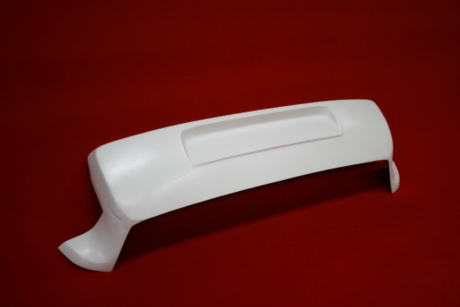
I'm thinking about buying GT complete fenders from a German company here, They are not just the bulges but complete fenders including sail panel and door frame. According to the 914 parts guy here, they are of good quality. This company also sells just the rear bulges but then a tad wider then the GT. I'm thinking of re-crafting these on the GT complete fenders and also buying the rear bumper/lip that fit's the new width and after making these to an exact fit, have them reproduced in Carbonfibre. Then also the rear trunk in CF.
I love the Sheridan rear, especially the wider one, but i would like to be able to open the trunk, on the other hand, I guess it would also be possible to adapt the sheridan to single fenders...
Here's what I mean
The GT fenders
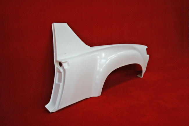
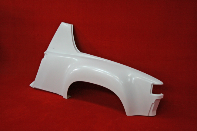
The tad wider fenders
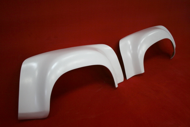
And the bumper to match
I'm thinking about buying GT complete fenders from a German company here, They are not just the bulges but complete fenders including sail panel and door frame. According to the 914 parts guy here, they are of good quality. This company also sells just the rear bulges but then a tad wider then the GT. I'm thinking of re-crafting these on the GT complete fenders and also buying the rear bumper/lip that fit's the new width and after making these to an exact fit, have them reproduced in Carbonfibre. Then also the rear trunk in CF.
I love the Sheridan rear, especially the wider one, but i would like to be able to open the trunk, on the other hand, I guess it would also be possible to adapt the sheridan to single fenders...
Here's what I mean
The GT fenders
The tad wider fenders
And the bumper to match
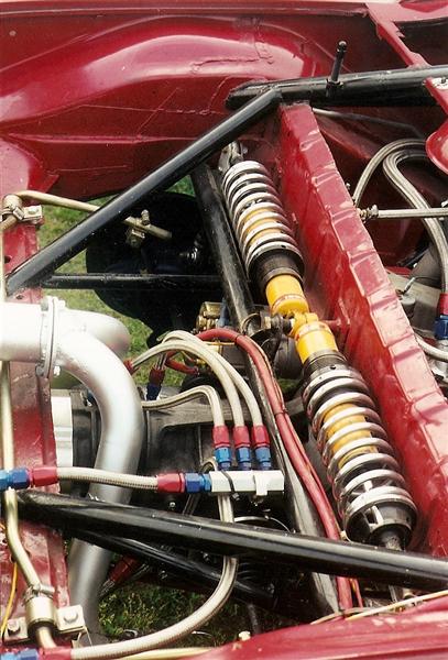
Great looking build.....your rear shock set up looks like what a friend of mine did to his race car....BTW this car is/was up for sale....unique center drive, hand built from the ground up 914 race car.....
Click to view attachment
Click to view attachment
Click to view attachment
Click to view attachment
Glad your Dog made it in the pic Can't wait to meet her Sunday.
Ferg
Can't wait to meet her Sunday.Ferg
QUOTE(jt914-6 @ Sep 29 2010, 03:24 AM)
Great looking build.....your rear shock set up looks like what a friend of mine did to his race car....BTW this car is/was up for sale....unique center drive, hand built from the ground up 914 race car.....
Click to view attachment
Do you have any more pictures of this car, looks very interesting. Does it have custom control arms in the rear?
-Britain
Yes, Very interesting.
Do you have a picture of the shock actuator pivot arm and mount? Do you know what the ratio used was?
LOVE THIS STUFF!
Do you have a picture of the shock actuator pivot arm and mount? Do you know what the ratio used was?
LOVE THIS STUFF!
Don't know about the actuator ratio or don't have a better pic....he was a little secretive about it but I'm sure he'd share info. He was a student of mine when I was instructing DE's. He's missed his calling in life. He built it from the ground up including body work & paint. PM me and I'll see if he'll share info. He's not a member of the world. Last time I talked to him it was for sale......
A older pic....
Click to view attachment
What it looks like now.....
Click to view attachment
A older pic....
Click to view attachment
What it looks like now.....
Click to view attachment
Nice...if it is for sale, try to get some more pictures.
-Britain
-Britain
Very nice car and amazing craftmanship, but I am always curious why someone puts so much money and time into a car and then sells it. Was the car not competitive? Hardship? Got bored of it and wanted to try something else? 
QUOTE(Steve @ Sep 29 2010, 06:03 PM)
Very nice car and amazing craftmanship, but I am always curious why someone puts so much money and time into a car and then sells it. Was the car not competitive? Hardship? Got bored of it and wanted to try something else?
He runs it in GT5 in PCA club racing and it has many wins and beats many others in higher classes. He's raced it and at least one other 914 for years. He is a family practice MD and I'm sure it has taken lots of his time. No hardship. As I said, he's missed his calling in life.
 Rear control arms are modified stock. I think he just may be tired of racing and his "pit crew" daughter is older now and is not going to races.
 A couple of more pics
Click to view attachment
Click to view attachment
Looks awesome. Where is it listed for sale?
Cool project, it's nice to see that a cantilever suspension like this has been done before on a 914, thanks for the pics!
QUOTE(plymouth37 @ Sep 29 2010, 11:30 PM)
Cool project, it's nice to see that a cantilever suspension like this has been done before on a 914, thanks for the pics!
Thanks......your car is going to be great.....hijack over.....anyone wanting to know more about the center drive 914.....pm me.....
I ran wheel to wheel against your friends car. Nice car
that was about 1996 ish...
heartland park, topeka kansas...
spoke with him at length. The car was a lot less modified then. He that same front hood (metal) and gave me the idea of doing it to my hood. That is actually how I learned to weld too. After talking to your friend and building up the courage, I bought a welder and cut my hood. First thing I ever MIG welded... Twas not pretty... but with enough bondo it worked fine.
brant
Dana... here's your thread. It's lonely. It wants more pictures of recent progress that you've done. 
It wants more pictures of recent progress that you've done.
QUOTE(RJMII @ Nov 20 2010, 02:50 PM)
Dana... here's your thread. It's lonely.
It wants more pictures of recent progress that you've done. Funny you should say that, I found a hole in my overwhelming school schedule to work on the beast, I am working out the geometry of the cantilever suspension now, should be able to post progress soon!
QUOTE(plymouth37 @ Nov 20 2010, 01:38 PM)
QUOTE(RJMII @ Nov 20 2010, 02:50 PM)
Dana... here's your thread. It's lonely.
It wants more pictures of recent progress that you've done. Funny you should say that, I found a hole in my overwhelming school schedule to work on the beast, I am working out the geometry of the cantilever suspension now, should be able to post progress soon!
![popcorn[1].gif](http://www.914world.com/bbs2/style_emoticons/default/popcorn[1].gif)

Yep
Here is what I have been playing with, it is a nice compact setup with a low cg. The springs are 400 lb/in and with the cantilever this is equivalent to about 250 lb/in at ride height and around 280 lb/in at full compression.
Click to view attachment
Click to view attachment
Just my 2C: but by putting the pivotpoint of the cantilever that far inward, in your setup, most of the force is used to raise the complete coilover instead of using that force to compress it. I could be wrong but by glancing over your drawing, that's the first thing that springs to my mind.
Randall
Randall
From what I can figure out, there is a good amount of force used to rotate the assembly but ultimately the spring should properly counteract the rotation of the cantilever arm. I could be wrong though, anybody else have a couple cents they want to pitch in?
Your upward movement of the trailing arm now results in a lateral force on the pivot arm. By moving the pivot point out and slightly tilting the triangle you get only vertical force as a result from trailing arm movement, this is what you want. The cantilever only translates this into lateral force onto the coilover. Avoiding slight up/down movement of the coilover is almost impossible, but in trying you wil get the best linear suspension travel.
Trying to find a pic, but doing this from my i-phone in a hotelroom...... Doesn't work
Randall
Trying to find a pic, but doing this from my i-phone in a hotelroom...... Doesn't work
Randall
I see what you are saying, I have played around with a couple designs that were closer to what you are talking about. My main issue with those designs i was that it forced me to mount the springs very high in the car in order to make the geometry work, which in turn was blocking the path for my exhaust to make it to the back of the car. Should have sucked it up and gone with double a-arms in the rear, would have made mounting shocks a lot easier.
some inspiration from our motorcycle friends
What would be the effect of a simple 90 deg bellcrank to transfer vertical motion into horizontal motion? The off center triangle designs exist for the tightest confines and non-linear travel like say bikes and such, like a mechanical means toward progressive action. Please correct me if I am wrong however.
This is what I was looking at before, a simple bell crank converting vertical motion to horizontal.
Click to view attachment
And here was my rendering using this concept.
Click to view attachment
I think this is the most straight forward solution but I was thinking about the offset cantilever because of space restrictions and the fact that the design above has a high center of gravity while the off set one is relatively low.
Click to view attachment
And here was my rendering using this concept.
Click to view attachment
I think this is the most straight forward solution but I was thinking about the offset cantilever because of space restrictions and the fact that the design above has a high center of gravity while the off set one is relatively low.
How do you guys think the handling would suffer if I went with the offset cantilever option? I think I am fine with the equivalent spring rate acting like a progressive spring adding around 7 pounds of extra spring force per inch of suspension compression, any opinions?
Here it is again for easy reference:
Click to view attachment
Here is a shot of an aftermarket wrangler suspension that looks similar, granted the Anklebiter will have a slightly different driving experience than this guy...
Click to view attachment
And another similar setup for a Nissan Titan:
Click to view attachment
My springs will be pointing towards each other rather than parallel but the lever action will work in the same way.
Dana, you make me sick. I love your work. Keep it going. I keep looking at the pictures I took when I was at your house and druel regularly.
QUOTE(plymouth37 @ Nov 21 2010, 12:07 PM)
How do you guys think the handling would suffer if I went with the offset cantilever option? I think I am fine with the equivalent spring rate acting like a progressive spring adding around 7 pounds of extra spring force per inch of suspension compression, any opinions?
My gut reaction is that the progressive change is a non-issue. I'm assuming the springs are maybe 1.5 orders of magnitude stiffer than the progressive increase so it probably will not be very noticeable at all.
One suggestion though. You might want to look into adding a bearing at the bellcrank's pivot point. While the car weights and hence suspension forces are radically different, we found the stiction to be pretty [unacceptably] high on our FSAE car with only a bushing.
QUOTE(jd74914 @ Nov 21 2010, 03:32 PM)
One suggestion though. You might want to look into adding a bearing at the bellcrank's pivot point. While the car weights and hence suspension forces are radically different, we found the stiction to be pretty [unacceptably] high on our FSAE car with only a bushing.
Good point, I had planned on using a bushing there but was wondering if it was going to be an issue.
I just spent two evenings reading all 33 pages. Absolutely amazing work. I'm inspired and motivated.
Bee Jay
Bee Jay
QUOTE(Bee Jay @ Nov 23 2010, 01:21 AM)
I just spent two evenings reading all 33 pages.
Don't be fooled. It is actually a clever ploy to soak up our time and keep us from working on or driving our cars. With the cumulative evenings people have spent reading this thread two or three complete cars could have been restored!
So I decided to go ahead with the design I posted earlier, I blew up my drawing to full size and made a template for the arms.
Click to view attachment
Today I built the suspension arms, I welded all of the seams from the inside, then welded and finished all of the seams on the outside. Now I have one bead of weld for structure and one for looks. I have a feeling I overbuilt the crap out of these but I would rather not risk it with suspension components. Even with the beefy arms this new suspension system weighs about a pound less per side than stock with a super low and inboard center of gravity.
I shot the arms with a coat of primer and will mock things up in the morning.
Click to view attachment
Click to view attachment
Click to view attachment
Today I built the suspension arms, I welded all of the seams from the inside, then welded and finished all of the seams on the outside. Now I have one bead of weld for structure and one for looks. I have a feeling I overbuilt the crap out of these but I would rather not risk it with suspension components. Even with the beefy arms this new suspension system weighs about a pound less per side than stock with a super low and inboard center of gravity.
I shot the arms with a coat of primer and will mock things up in the morning.
Click to view attachment
Click to view attachment
This is a "lo-fi" version of our main content. To view the full version with more information, formatting and images, please click here.