|
|
|
|
|
|
Here are some pics of my cage during construction. Attached thumbnail(s) 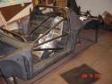 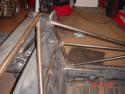 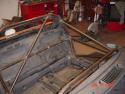 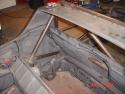
Pics Attached thumbnail(s) 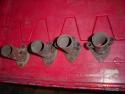 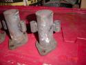 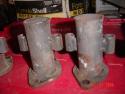 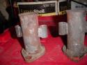 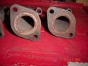 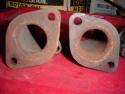 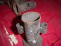
---------Updated test results---------- Second experiment- This time I submersed my 2 CHTs with the VDO CHT and a digital thermometer in cooking oil in a crock pot. I left the crock pot on for the entire experiment and stirred the pot before each reading. Here's the chart: 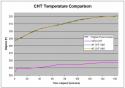 ------------------------------------------ So, I've had some trouble with CHTs being too high in racing conditions. I've worked and reworked the cooling system a number of times. But the CHTs are still too high. That's led us to question the readings I'm getting from my system. Currently I have a CHT sender under plug #1 and #3 and they connect to my AIM data logger. Jake suggested I get a VDO CHT guage to compare the two readings. So, I put the VDO CHT spark plug ring on top of my #1 CHT for the data logger and screwed the plug into the head and started the engine. The #1 CHT reads "T3" on the data logger display. I took several pictures as the engine warmed up and cooled off. First picture: 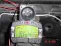 1 minute later: 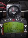 11 minutes later: (engine still on) 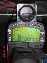 17 minutes later.... engine off now: 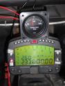 35 minutes later... engine off: 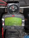 100 minutes after the first pic: 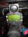 Here is a pic of the sender that I use with the data logger: 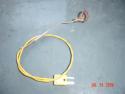 It sure seems like the VDO guage has a significant delay associated with it's display. I'm not sure I can conclude that my system is telling me the wrong temperature, but I can conclude that the two systems have very different reaction times.
I'm using the left headlight bucket for the oil cooler. With the dry sump system I only use the bumper/foglight opening and still get too much cooling on the track. On the right I use the foglight opening to get cooling air to the engine. Attached thumbnail(s) 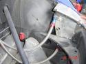 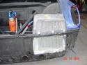 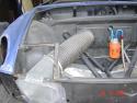
I'm having a 1-piece front clip developed for the 914. Bumper, air dam and splitter all one piece and made of carbon fiber. Here are some pics of the plug which will be used to make the mold. The template for the splitter is the piece of cardboards underneath the front flip. It's made to be legal for SCCA rules... can't extend beyond the outline of the bumper as seen from above. These will be for sale later this summer. You can buy the front clip only or get the front clip and splitter. They will be very light and very strong.... strong enough to punt Miatas, I'm told. If you want a larger splitter, we can do that, too. Attached thumbnail(s) 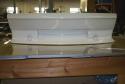 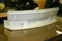 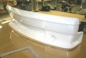 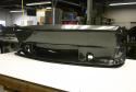 
Here's a few pics of the rear damper and upper chassis mount... again Koni double adjustable. Attached thumbnail(s) 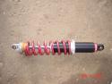 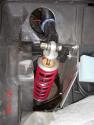
I fabricated a mounting bracket for the steering gear, since I no longer require the front subframe. This also moved the steering gear upwards in the body to help with bump steer. Attached thumbnail(s) 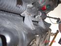
The front suspension...... I use Koni double adjustable inserts. Significantly shorter than stock, which is why I had to shorted the struts to accomodate them (the amount removed is shown in one of the pics), but I have 1" of travel before the jounce rubbers contact at my ride height. I also welded up the ball joint bolt and drilled and tapped the bottom of the strut to accept a 3/4" bolt. The bolt is hollow so I can use a screwdriver to adjust compression on the damper. The bolt goes through the 2 3/4" rod ends, which serve as the ball joint. The threaded tubes (gold in color) are attached to the chassis at the center to optimize the roll center geometry. I can adjust the track, wheelbase, caster and camber with these threaded tubes. The top of the strut attaches to the chassis with a homemade camber plate, where I can also adjust camber (and the rebound adjustment on the damper). The threaded spring perch sits on the strut. Attached thumbnail(s) 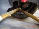 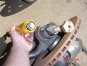 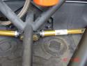 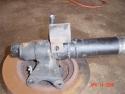 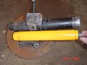 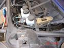 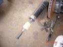 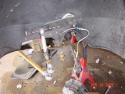 |


 Nov 6 2006, 08:13 AM