|
|
|
Porsche, and the Porsche crest are registered trademarks of Dr. Ing. h.c. F. Porsche AG.
This site is not affiliated with Porsche in any way. Its only purpose is to provide an online forum for car enthusiasts. All other trademarks are property of their respective owners. |
|
|

  |

| watsonrx13 |
 Mar 26 2010, 03:58 PM Mar 26 2010, 03:58 PM
Post
#1
|
|
Advanced Member  Group: Members Posts: 2,735 Joined: 18-February 03 From: Plant City, FL Member No.: 312 Region Association: South East States |
I'm in the process of checking the lift of the new cams I purchased from Jake. I would like to verify that I have the dial indicator positioned correctly to check the lift. Is this correct?
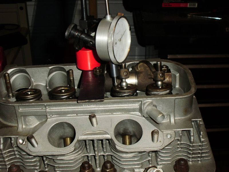 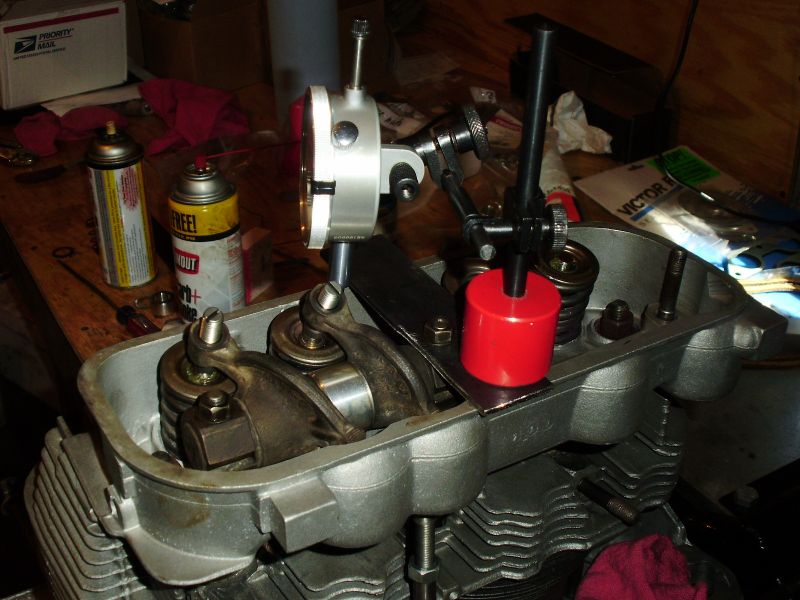 -- Rob |
   |

 
|
| McMark |
Mar 26 2010, 06:00 PM
Post
#2
|
|
914 Freak! Group: Retired Admin Posts: 20,179 Joined: 13-March 03 From: Grand Rapids, MI Member No.: 419 Region Association: None |
It's pretty good. Can't really tell because your two pictures are nearly 180* apart, which means it's essentially the same perspective. Take two pictures 90* apart (on from the 'front' and one from the 'left').
|
|
|
|
| McMark |
Mar 26 2010, 06:04 PM
Post
#3
|
|
914 Freak! Group: Retired Admin Posts: 20,179 Joined: 13-March 03 From: Grand Rapids, MI Member No.: 419 Region Association: None |
See....
Attached image(s) 
|
|
|
|
| URY914 |
Mar 26 2010, 06:16 PM
Post
#4
|
|
I built the lightest 914 in the history of mankind. Group: Members Posts: 121,070 Joined: 3-February 03 From: Jacksonville, FL Member No.: 222 Region Association: None |
Why are you checking this?
|
|
|
|
| ME733 |
Mar 26 2010, 07:01 PM
Post
#5
|
|
Senior Member Group: Members Posts: 842 Joined: 25-June 08 From: Atlanta Ga. Member No.: 9,209 Region Association: South East States |
......................I would suggest the following.....1) Rig up an entirely different way to mount and locate the dial indicator.( a c-clamp to the D.I. base and head or fins.).OR use the intake manafold studs for the plate/ D.I. location...2). you want to have ALL the hold down nuts for the rocker arm shaft studs, torqued properly.(with out your plate possably distorting alignment of R.A shaft.3). INSTALL and tighten the adjuster nuts.4) determine how you will measure the cam-@ .020- or @.050 ths...and ensure the D.I. has complete travel..(plus enought extra to keep tension on the guage/dial.)., from completely open to closed...and of course the 50% lift/rocker arm alignment completed...........................murray
|
|
|
|
| watsonrx13 |
Mar 26 2010, 09:22 PM
Post
#6
|
|
Advanced Member Group: Members Posts: 2,735 Joined: 18-February 03 From: Plant City, FL Member No.: 312 Region Association: South East States |
Thanks guys. I'll realign the DI to be more parallel with the valve. The plate isn't interferring with the RA, but I'll check another location for the plate.
-- Rob |
|
|
|
| watsonrx13 |
Mar 26 2010, 09:23 PM
Post
#7
|
|
Advanced Member Group: Members Posts: 2,735 Joined: 18-February 03 From: Plant City, FL Member No.: 312 Region Association: South East States |
QUOTE(URY914 @ Mar 26 2010, 07:16 PM)  Why are you checking this? Installing one of Jake's complete cam kit. -- Rob |
|
|
|
| McMark |
Mar 27 2010, 01:37 AM
Post
#8
|
|
914 Freak! Group: Retired Admin Posts: 20,179 Joined: 13-March 03 From: Grand Rapids, MI Member No.: 419 Region Association: None |
Aligning the dial indicator is a PITA. (IMG:style_emoticons/default/wink.gif) You have my sympathy.
|
|
|
|
| watsonrx13 |
Mar 27 2010, 04:31 AM
Post
#9
|
|
Advanced Member Group: Members Posts: 2,735 Joined: 18-February 03 From: Plant City, FL Member No.: 312 Region Association: South East States |
QUOTE(McMark @ Mar 27 2010, 02:37 AM) Thanks for the sympathy... I've got ALL day to get the measurements. I'll take more pics... -- Rob |
|
|
|
| McMark |
Mar 27 2010, 09:52 AM
Post
#10
|
|
914 Freak! Group: Retired Admin Posts: 20,179 Joined: 13-March 03 From: Grand Rapids, MI Member No.: 419 Region Association: None |
Yup, keep 'em coming. Remember, 90* apart. (IMG:style_emoticons/default/wink.gif)
|
|
|
|
| J P Stein |
Mar 27 2010, 10:05 AM
Post
#11
|
|
Irrelevant old fart Group: Members Posts: 8,797 Joined: 30-December 02 From: Vancouver, WA Member No.: 45 Region Association: None |
You need to keep the indicator follower perpendicular (square in 2 directions) to the retainer....it is square to the valve. Eyeballing it is close enuff. For what you are doing the cosine error you'll get is insignificant.
|
|
|
|
| watsonrx13 |
Mar 27 2010, 02:57 PM
Post
#12
|
|
Advanced Member Group: Members Posts: 2,735 Joined: 18-February 03 From: Plant City, FL Member No.: 312 Region Association: South East States |
After a hard day working, here's the pics with the dial indicator on the heads.
First shot  Second shot  Here's a shot at half the lift, checking the position of the adjustor and the valve.  So, does anyone see any glaring problems/issues? -- Rob |
|
|
|
| McMark |
Mar 27 2010, 04:27 PM
Post
#13
|
|
914 Freak! Group: Retired Admin Posts: 20,179 Joined: 13-March 03 From: Grand Rapids, MI Member No.: 419 Region Association: None |
Yeah, your pushrod is WAAAAAAY too short. The adjuster screw is nowhere near in line with the valve at half lift. Looks to me to be about 15* off or so, and it should be nearly 0*.
Attached image(s) 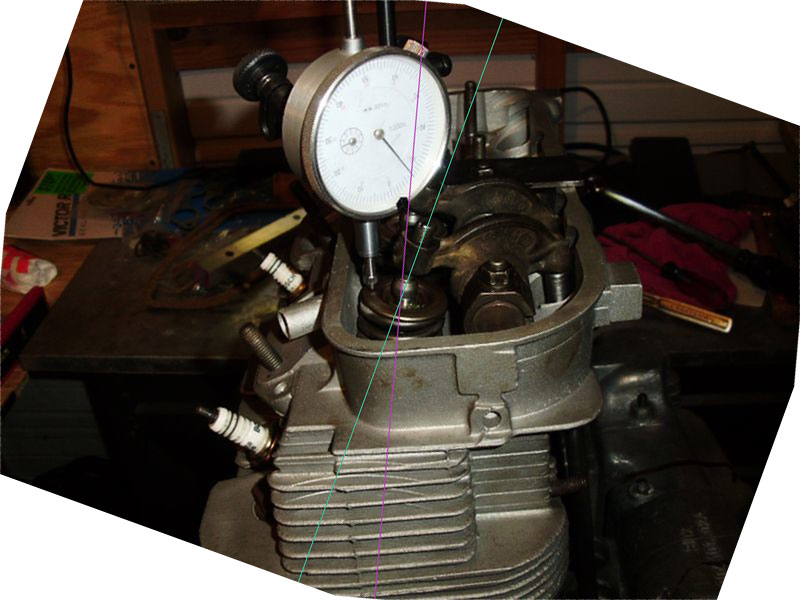
|
|
|
|
| rudedude |
Mar 27 2010, 04:40 PM
Post
#14
|
|
Senior Member Group: Members Posts: 511 Joined: 1-January 05 From: minneapolis, mn Member No.: 3,387 Region Association: Upper MidWest |
Did you clearance your rocker arms for the longer swivel adjusters?
Just curious. |
|
|
|
| watsonrx13 |
Mar 27 2010, 05:08 PM
Post
#15
|
|
Advanced Member Group: Members Posts: 2,735 Joined: 18-February 03 From: Plant City, FL Member No.: 312 Region Association: South East States |
QUOTE(rudedude @ Mar 27 2010, 05:40 PM) Did you clearance your rocker arms for the longer swivel adjusters? Just curious. No, I'm using the standard 1.7l rocker arms. Can you explain what is needed? -- Rob |
|
|
|
| watsonrx13 |
Mar 27 2010, 05:16 PM
Post
#16
|
|
Advanced Member Group: Members Posts: 2,735 Joined: 18-February 03 From: Plant City, FL Member No.: 312 Region Association: South East States |
QUOTE(McMark @ Mar 27 2010, 05:27 PM) Yeah, your pushrod is WAAAAAAY too short. The adjuster screw is nowhere near in line with the valve at half lift. Looks to me to be about 15* off or so, and it should be nearly 0*. So the valve and the adjuster screw should be exactly in line with each other? Does the beginning shots look correct? In Jake's valve train geometry he mentions shims for the rocker arms, would this be necessary for this installation? Do you have any pics showing the correct 1/2 lift position? -- Rob |
|
|
|
| McMark |
Mar 27 2010, 05:20 PM
Post
#17
|
|
914 Freak! Group: Retired Admin Posts: 20,179 Joined: 13-March 03 From: Grand Rapids, MI Member No.: 419 Region Association: None |
Yes they should be in line. Did you get new pushrods? Did you make your own?
|
|
|
|
| rudedude |
Mar 27 2010, 05:21 PM
Post
#18
|
|
Senior Member Group: Members Posts: 511 Joined: 1-January 05 From: minneapolis, mn Member No.: 3,387 Region Association: Upper MidWest |
I believe you need to clearance somewhere in neighborhood of 0.150" so that you get the proper geometry.
There are way more knowledgeable people here than me who know this without searching. Jule |
|
|
|
| McMark |
Mar 27 2010, 05:23 PM
Post
#19
|
|
914 Freak! Group: Retired Admin Posts: 20,179 Joined: 13-March 03 From: Grand Rapids, MI Member No.: 419 Region Association: None |
Here's a sample pic. It's not the clearest, and I can't remember if this is set perfectly at half lift, or just close. But you can see the valve and the adjuster are pretty much in line.
Attached image(s) 
|
|
|
|
| watsonrx13 |
Mar 27 2010, 06:00 PM
Post
#20
|
|
Advanced Member Group: Members Posts: 2,735 Joined: 18-February 03 From: Plant City, FL Member No.: 312 Region Association: South East States |
QUOTE(McMark @ Mar 27 2010, 06:20 PM) Yes they should be in line. Did you get new pushrods? Did you make your own? I have new push rods and I purchased the adjustable push rod from Jake. As rudedude suggested, should I clearance the rocker arms for the 911 swivel seats? -- Rob |
|
|
|
|
2 User(s) are reading this topic (2 Guests and 0 Anonymous Users)
0 Members:

|
Lo-Fi Version | Time is now: 11th June 2024 - 12:34 AM |
Invision Power Board
v9.1.4 © 2024 IPS, Inc.