|
|
|
Porsche, and the Porsche crest are registered trademarks of Dr. Ing. h.c. F. Porsche AG.
This site is not affiliated with Porsche in any way. Its only purpose is to provide an online forum for car enthusiasts. All other trademarks are property of their respective owners. |
|
|

  |

| TonyAKAVW |
 Oct 14 2004, 05:40 PM Oct 14 2004, 05:40 PM
Post
#1
|
|
That's my ride.  Group: Members Posts: 2,151 Joined: 17-January 03 From: Redondo Beach, CA Member No.: 166 Region Association: None |
I'm building a "roto-lok" system http://www.roto-lok.com/tech/technology.html
for the rotation of an antenna for amateur (ham) radio purposes. I'm trying to find an equation that relates the radius of a pulley/drum to the total friction. Basically I want to make sure that I put sufficient turns of wire around the drive shaft so that it does not slip. I've been searching on the web and I can't even really find equations relating tension to friction, etc. Any advice on where to look? -Tony |
   |

 
|
| john rogers |
Oct 14 2004, 05:55 PM
Post
#2
|
|
Senior Member Group: Members Posts: 1,525 Joined: 4-March 03 From: Chula Vista CA Member No.: 391 |
If I remember my naval engineering correctly about winches and capstans, the diameter only affects the number of turns of the driver/driven to turn some number of degrees. It is the number of wraps of wire/cable/line/rope and their tension that determines the amount of slippage. An additional factor is the weight of what you are trying to turn and the friction of the bearings supporting the driven load. I'd say you'll have to make a good guess and try it?
|
|
|
|
| TonyAKAVW |
Oct 14 2004, 06:07 PM
Post
#3
|
|
That's my ride. Group: Members Posts: 2,151 Joined: 17-January 03 From: Redondo Beach, CA Member No.: 166 Region Association: None |
Well, lets say there is one turn on the large drum, with some resulting friction. The capstan must at the least be able to provde this same friction, or else the cable will slip on the capstan. I plan on increasing the friction by adding more turns of cable to the capstan. What I want to know is how to calculate the number of turns for the capstan given that the coefficients of friction are the same, but the radii are different. I think that the weight that I'm turning doesn't factor in to finding this out.
Now if I find that I need to have two turns on the large drum, then I would have to double the turns on the capstan. I'm planing on using as many seperate strands as I can to make the coupling as stiff as possible, but that is in part at least constrained by the number of turns I need on the capstan to prevent slippage since the capstan is not extremely wide. For the bearings, I'm using needle bearings on precision gound hardened shafts, so I don't think their friction will be a dominant force here???? -Tony |
|
|
|
| TimT |
Oct 14 2004, 06:12 PM
Post
#4
|
|
retired Group: Members Posts: 4,033 Joined: 18-February 03 From: Wantagh, NY Member No.: 313 |
Lots of variables in this one
tension on the tail end of cable dia of cable total length of cable bearing coefficient of friction of the surface of the capstan coefficient of friction the cable speed in radians the capstan is turning... Or as John mentions make a guess and try.. sometimes its easier to try and see what happens than calculate When I worked on charte boats we anchored in about 100' of water usually a 100lb anchor, two turns on the capstan and the hook came up. friction (mu) is either added or subtracted from equations..... You need to pursue equations involving rotation in a shaft.. torsion equations.. j=(pi*d^4)/32 etc just have to introduce slippage into that.. |
|
|
|
| TonyAKAVW |
Oct 14 2004, 06:18 PM
Post
#5
|
|
That's my ride. Group: Members Posts: 2,151 Joined: 17-January 03 From: Redondo Beach, CA Member No.: 166 Region Association: None |
Thanks! I'll do some searching with those terms.
I would think though that tension, cable diameter and other constants (coefficients of friction are the same since in both cases its stainless steel against aluminum) would fall out of the equations when making a ratio of two equations to obtain N, a ratio of turns on capstan to turns on the driven drum. Just trying it out is probably the best way to go, probably wouldn't be too hard to setup something to test that, but being an engineer (albeit electrical) I just feel compelled to find the optimal solution. -Tony |
|
|
|
| Carl |
Oct 14 2004, 06:26 PM
Post
#6
|
|
Ummm ... what? Group: Members Posts: 781 Joined: 17-January 03 From: San Jose, CA Member No.: 163 Region Association: Northern California |
Other approaches would be to use a chain & sprocket or a serpentine belt. Is your tower for a low band array or VHF/UHF? A low band array would have a lot of wind loading and leverage.
C |
|
|
|
| MattR |
Oct 14 2004, 06:50 PM
Post
#7
|
|
Advanced Member Group: Members Posts: 3,279 Joined: 23-January 04 From: SF Bay Area Member No.: 1,589 Region Association: Northern California |
ugh, i just signed on to take a break from my statics homework...
|
|
|
|
| TonyAKAVW |
Oct 14 2004, 07:17 PM
Post
#8
|
|
That's my ride. Group: Members Posts: 2,151 Joined: 17-January 03 From: Redondo Beach, CA Member No.: 166 Region Association: None |
Actually this is for adjusting the elevation angle for microwave and millimeterwave antennas, as well as an optical transceiver. The beamwidth of the antennas is less than 1 degree and for the optical equipment, far less than 1 degree. For the optical setup I'm going to use this elevation control as a rough alignment and then micropositioner motors (with 2 um resolution) for fine adjustments. Each transceiver is about 30 lbs and on will be used at a time.
So basically this thing has to have zero backlash and tight coupling, as well as zero slippage. That for the most part rules out gears and chains, though I suppose zero-backlash gears could be used. Belts would also work I suppose To get an idea of the size of things, the driven drum will be 6 inches in diameter and the drive capstan, 3/4 inch diameter, both made from 6061 aluminum billet. Initially it will be hand controlled, but eventually I'll add stepper motors so that I can computerize it and automatically track a received signal for best performance. -Tony |
|
|
|
| F4i |
Oct 14 2004, 09:06 PM
Post
#9
|
|
914 DOG! Group: Benefactors Posts: 482 Joined: 22-December 03 From: AB Canada Member No.: 1,460 |
You could use coged belts. Like the kind used for cam belts in engines. Add a tensioner and there you go. thats my way, no math. (IMG:style_emoticons/default/biggrin.gif)
|
|
|
|
| groot |
Oct 15 2004, 06:03 AM
Post
#10
|
|
Dis member Group: Members Posts: 897 Joined: 17-December 03 From: Michigan Member No.: 1,444 |
Is this for home use? If so, I think I'd make a gross adjustment with a simple friction stop and use a fine adjustment with a screw. You can extend the lever arm on the screw so that one turn of the screw results in some very small increment of movement giving you as fine of an adjustment as you need.
Just thinking some more on this setup...... I see a drum on a plate that has a friction stop that holds you antennae and the plate is attached to a stand (or table) using fine adjustors. |
|
|
|
| TonyAKAVW |
Oct 15 2004, 12:30 PM
Post
#11
|
|
That's my ride. Group: Members Posts: 2,151 Joined: 17-January 03 From: Redondo Beach, CA Member No.: 166 Region Association: None |
Its sort of for home use. Its more for mountaintop use. Microwaves travel a lot like light so you have to have a clear line-of-sight to the other station to communicate. So two weekends a year there's a contest and everyone goes up to mountaintops to see how far they can talk and to how many people. So it has to withstand soem abuse and still be accurate.
Here's a drawing of what it looks like currently... -Tony Attached image(s) 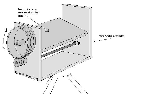
|
|
|
|
|
1 User(s) are reading this topic (1 Guests and 0 Anonymous Users)
0 Members:

|
Lo-Fi Version | Time is now: 16th July 2025 - 04:28 PM |
Invision Power Board
v9.1.4 © 2025 IPS, Inc.