|
|
|
Porsche, and the Porsche crest are registered trademarks of Dr. Ing. h.c. F. Porsche AG.
This site is not affiliated with Porsche in any way. Its only purpose is to provide an online forum for car enthusiasts. All other trademarks are property of their respective owners. |
|
|

  |

| CptTripps |
 Apr 28 2014, 10:20 PM Apr 28 2014, 10:20 PM
Post
#1
|
|
:: Punch and Pie ::  Group: Members Posts: 3,584 Joined: 26-December 04 From: Mentor, OH Member No.: 3,342 Region Association: Upper MidWest |
I've tried to make sense of the tiring diagram, but without any numbers on the pins, in lost. I took a multi-meter to it today? And only got a few of the easy ones figured out. Does anyone have a complete pin-out diagram for the connections on the steering wheel?
Turn signals? Wiper seiitngs? Flasher? Horn? Washer? The ignition was easier, but P and X still elude me. |
   |

 
|
| Eric_Shea |
Apr 28 2014, 11:01 PM
Post
#2
|
|
PMB Performance Group: Admin Posts: 19,278 Joined: 3-September 03 From: Salt Lake City, UT Member No.: 1,110 Region Association: Rocky Mountains |
Early? 12 pin?
|
|
|
|
| HalfMoon |
Apr 28 2014, 11:15 PM
Post
#3
|
|
Senior Member Group: Members Posts: 828 Joined: 13-November 12 From: Shenandoah Junction, WV Member No.: 15,144 Region Association: MidAtlantic Region |
|
|
|
|
| CptTripps |
Apr 28 2014, 11:50 PM
Post
#4
|
|
:: Punch and Pie :: Group: Members Posts: 3,584 Joined: 26-December 04 From: Mentor, OH Member No.: 3,342 Region Association: Upper MidWest |
1975
Although, I do have a 73 steering column but I think it's the same |
|
|
|
| jcd914 |
Apr 29 2014, 01:36 AM
Post
#5
|
|
Advanced Member Group: Members Posts: 2,081 Joined: 7-February 08 From: Sacramento, CA Member No.: 8,684 Region Association: Northern California |
Here is a picture of the column switches looking from below/behind and what the terminals are marked as on the switch.
ID and reference to where you can find these on the 1973 wiring diagram from Pelican. The 31, 53, 53E, 53A & 53C are the Wiper switch (E, Tracks 6 - 10 on WD) The PL, P & PR are the Parking light switch (E19, Track 30 on WD) The 49A, L & R are the Turn signal switch (E2, Track 42 on WD) The S, S- & 31 are the Dimmer(S) & Horn Switch(S-) (E4 & H, Tracks 16 & 17 on WD) Jim Note: in my picture I have mis-marked the 31, 53A, & 53B Terminals on the wiper switch. On closer look what I have marked as 53A is really 53E and What I have marked as 53B is really 53A and 31 is really S1. Yes I am over due to see the eye doctor (IMG:style_emoticons/default/sad.gif) 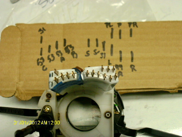 |
|
|
|
| CptTripps |
Apr 29 2014, 06:50 AM
Post
#6
|
|
:: Punch and Pie :: Group: Members Posts: 3,584 Joined: 26-December 04 From: Mentor, OH Member No.: 3,342 Region Association: Upper MidWest |
So, if I'm reading that correctly...is this diagram correct?
(Please help me fill in the blanks if I'm wrong, I want to make sure this is out there for others in the future) Attached image(s) 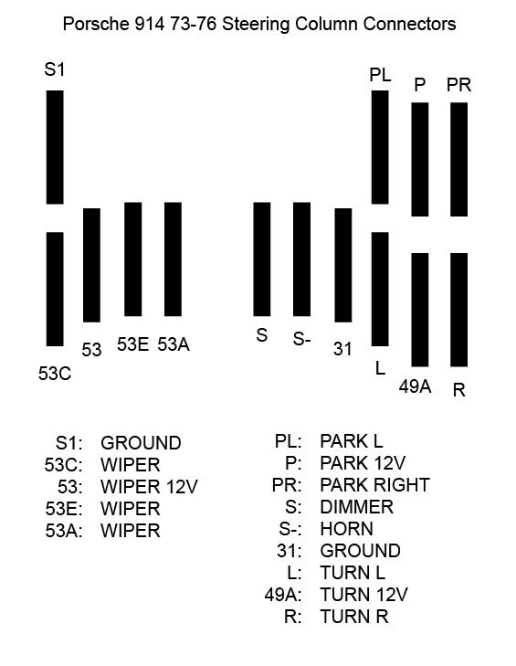
|
|
|
|
| OU8AVW |
Apr 29 2014, 03:19 PM
Post
#7
|
|
Yacht Rigger Group: Members Posts: 1,803 Joined: 1-October 08 From: Granbury, TX Member No.: 9,601 Region Association: Southwest Region |
Brad Mayeur was going to give me a diagram but I just bought a replacement column. Might be worth an email to him. He's super helpful all be a bit busy...
|
|
|
|
| Cap'n Krusty |
Apr 29 2014, 04:14 PM
Post
#8
|
|
Cap'n Krusty Group: Members Posts: 10,794 Joined: 24-June 04 From: Santa Maria, CA Member No.: 2,246 Region Association: Central California |
Look at the wiring diagram, or in this case, the flow chart. The color of each and every wire is on the chart, along with terminal information.
The Cap'n |
|
|
|
| CptTripps |
Apr 29 2014, 05:44 PM
Post
#9
|
|
:: Punch and Pie :: Group: Members Posts: 3,584 Joined: 26-December 04 From: Mentor, OH Member No.: 3,342 Region Association: Upper MidWest |
QUOTE(Cap'n Krusty @ Apr 29 2014, 06:14 PM)  Look at the wiring diagram, or in this case, the flow chart. The color of each and every wire is on the chart, along with terminal information. The Cap'n I agree, but stuff like this is easier for some of us to follow. That diagram and flow isn't the easiest for me to dissect quickly. Besides, I'm making a custom harness. |
|
|
|
| r_towle |
Apr 29 2014, 06:20 PM
Post
#10
|
|
Custom Member Group: Members Posts: 24,585 Joined: 9-January 03 From: Taxachusetts Member No.: 124 Region Association: North East States |
QUOTE(jcd914 @ Apr 29 2014, 03:36 AM) Here is a picture of the column switches looking from below/behind and what the terminals are marked as on the switch. ID and reference to where you can find these on the 1973 wiring diagram from Pelican. The 31, 53, 53E, 53A & 53C are the Wiper switch (E, Tracks 6 - 10 on WD) The PL, P & PR are the Parking light switch (E19, Track 30 on WD) The 49A, L & R are the Turn signal switch (E2, Track 42 on WD) The S, S- & 31 are the Dimmer(S) & Horn Switch(S-) (E4 & H, Tracks 16 & 17 on WD) Jim Note: in my picture I have mis-marked the 31, 53A, & 53B Terminals on the wiper switch. On closer look what I have marked as 53A is really 53E and What I have marked as 53B is really 53A and 31 is really S1. Yes I am over due to see the eye doctor (IMG:style_emoticons/default/sad.gif) Wow, This place always amazes me. |
|
|
|
| CptTripps |
Apr 30 2014, 08:58 AM
Post
#11
|
|
:: Punch and Pie :: Group: Members Posts: 3,584 Joined: 26-December 04 From: Mentor, OH Member No.: 3,342 Region Association: Upper MidWest |
I took all the pics of the wiring diagram I could find, cleaned them up, stitched them together, and enhanced the text so some parts are more readable.
Download here if you want it. PNG: https://dl.dropboxusercontent.com/u/2853885...ing-diagram.png JPG: https://dl.dropboxusercontent.com/u/2853885...ing-diagram.jpg I'm sure it's been done before, but this may help someone out that's searching for documentation. |
|
|
|
| barefoot |
Apr 30 2014, 10:53 AM
Post
#12
|
|
Senior Member Group: Members Posts: 1,279 Joined: 19-March 13 From: Charleston SC Member No.: 15,673 Region Association: South East States |
QUOTE(CptTripps @ Apr 30 2014, 10:58 AM) I took all the pics of the wiring diagram I could find, cleaned them up, stitched them together, and enhanced the text so some parts are more readable. Download here if you want it. I'm sure it's been done before, but this may help someone out that's searching for documentation. Thanks Doug; this is a big help. Now I can crawl under the dash with my laptop on my belly and see things nice & large. Barefoot (Formerly from Cleve town) |
|
|
|
| worn |
Apr 30 2014, 11:38 AM
Post
#13
|
|
can't remember Group: Members Posts: 3,156 Joined: 3-June 11 From: Madison, WI Member No.: 13,152 Region Association: Upper MidWest |
QUOTE(CptTripps @ Apr 28 2014, 08:20 PM) I've tried to make sense of the tiring diagram, but without any numbers on the pins, in lost. I took a multi-meter to it today? And only got a few of the easy ones figured out. Does anyone have a complete pin-out diagram for the connections on the steering wheel? Turn signals? Wiper seiitngs? Flasher? Horn? Washer? The ignition was easier, but P and X still elude me. Thanks, I am trying to hook up an intermittent relay. This will help. Now, tell me, was that a mistake or really clever in calling it a "tiring diagram"? Mine are on the ipad so I get nice sharp colors. Flipping through the pages will make your head spin. (IMG:style_emoticons/default/chair.gif) |
|
|
|
| worn |
Apr 30 2014, 11:39 AM
Post
#14
|
|
can't remember Group: Members Posts: 3,156 Joined: 3-June 11 From: Madison, WI Member No.: 13,152 Region Association: Upper MidWest |
QUOTE(CptTripps @ Apr 30 2014, 06:58 AM) I took all the pics of the wiring diagram I could find, cleaned them up, stitched them together, and enhanced the text so some parts are more readable. I'm sure it's been done before, but this may help someone out that's searching for documentation. OOOOOHHH! Nice. (IMG:style_emoticons/default/piratenanner.gif) |
|
|
|
| worn |
Apr 30 2014, 11:41 AM
Post
#15
|
|
can't remember Group: Members Posts: 3,156 Joined: 3-June 11 From: Madison, WI Member No.: 13,152 Region Association: Upper MidWest |
[quote name='r_towle' date='Apr 29 2014, 04:20 PM' post='2031056']
[/quote] Wow, This place always amazes me. [/quote] I have been trying to find the early 924 stalk to get the washer switch built in. I can only find the later models that don't match. Are there any VW stalks without the hose tubes and with a washer switch that will fit? |
|
|
|
| JeffBowlsby |
May 1 2014, 12:21 AM
Post
#16
|
|
914 Wiring Harnesses Group: Members Posts: 8,524 Joined: 7-January 03 From: San Ramon CA Member No.: 104 Region Association: None |
These diagrams are incorrect, please delete and post new corrected versions. The problem with leaving these is that people save them, rely on them, and repost them - when they are not correct, so misinformation is spread.
Check the markings on the connector housings, at least the S, S- and 31 cavities are mis-located on the diagram. I did not check everything, there may be other issues. |
 |
|
| jcd914 |
May 1 2014, 01:04 AM
Post
#17
|
|
Advanced Member Group: Members Posts: 2,081 Joined: 7-February 08 From: Sacramento, CA Member No.: 8,684 Region Association: Northern California |
QUOTE(Jeff Bowlsby @ Apr 30 2014, 11:21 PM) These diagrams are incorrect, please delete and post new corrected versions. The problem with leaving these is that people save them, rely on them, and repost them - when they are not correct, so misinformation is spread. Check the markings on the connector housings, at least the S, S- and 31 cavities are mis-located on the diagram. I did not check everything, there may be other issues. If these are incorrect please post a correction! |
|
|
|
| CptTripps |
May 1 2014, 05:39 AM
Post
#18
|
|
:: Punch and Pie :: Group: Members Posts: 3,584 Joined: 26-December 04 From: Mentor, OH Member No.: 3,342 Region Association: Upper MidWest |
QUOTE(CptTripps @ Apr 29 2014, 08:50 AM) So, if I'm reading that correctly...is this diagram correct? (Please help me fill in the blanks if I'm wrong, I want to make sure this is out there for others in the future) QUOTE(Jeff Bowlsby @ May 1 2014, 02:21 AM) These diagrams are incorrect, please delete and post new corrected versions. The problem with leaving these is that people save them, rely on them, and repost them - when they are not correct, so misinformation is spread. Check the markings on the connector housings, at least the S, S- and 31 cavities are mis-located on the diagram. I did not check everything, there may be other issues. That's why I asked. If they are wrong, please correct them and I'll update the diagram. I know the other one is correct, as that's just a cleaned up version of the one from the 914 service manual. |
|
|
|
| JeffBowlsby |
May 1 2014, 03:13 PM
Post
#19
|
|
914 Wiring Harnesses Group: Members Posts: 8,524 Joined: 7-January 03 From: San Ramon CA Member No.: 104 Region Association: None |
I brought one issue to your attention, you are in a better position than anyone else to change your diagram and back-check your work.
|
|
|
|
| jcd914 |
May 1 2014, 03:52 PM
Post
#20
|
|
Advanced Member Group: Members Posts: 2,081 Joined: 7-February 08 From: Sacramento, CA Member No.: 8,684 Region Association: Northern California |
QUOTE(Jeff Bowlsby @ May 1 2014, 02:13 PM) I brought one issue to your attention, you are in a better position than anyone else to change your diagram and back-check your work. You said "at least the S, S- and 31 cavities are mis-located", based on what? No offense intended but I would like some explanation of what you think is wrong here and why you think it is wrong. Do I have the order wrong? Is it S-, S, 31 or 31, S, S- or what? My switches are packed back in the plastic tub and in my shed where I pulled them from, so it is not as simple as just looking at the pin ID's again. I will recheck the S, S- & 31 pins when I have time but that won't be for several days at least. I will be at Laguna Seca for the races tonight thru Sunday and then putting my trailer back in storage on Monday. Jim |
|
|
|
|
1 User(s) are reading this topic (1 Guests and 0 Anonymous Users)
0 Members:

|
Lo-Fi Version | Time is now: 31st May 2024 - 09:48 PM |
Invision Power Board
v9.1.4 © 2024 IPS, Inc.