|
|
|
Porsche, and the Porsche crest are registered trademarks of Dr. Ing. h.c. F. Porsche AG.
This site is not affiliated with Porsche in any way. Its only purpose is to provide an online forum for car enthusiasts. All other trademarks are property of their respective owners. |
|
|

  |

| dt4 |
 Jun 5 2021, 01:18 AM Jun 5 2021, 01:18 AM
Post
#1
|
|
Senior Member  Group: Members Posts: 503 Joined: 26-May 19 From: England Member No.: 23,161 Region Association: England |
Would someone with the tubes and flapper boxes and all the pipes into the cabin be able to take photos to show how it all fits together please (a full system in place)
plus photos from the top showing the fan placement and position plus the routing for the tubes etc.... I have a box of parts minus some of the flexible tubing and I am trying to figure how it all goes together and what I am missing thank you dt |
   |

 
|
| Front yard mechanic |
Jun 5 2021, 01:57 PM
Post
#2
|
|
Senior Member Group: Members Posts: 1,172 Joined: 23-July 15 From: New Mexico Member No.: 18,984 Region Association: None |
QUOTE(dt4 @ Jun 4 2021, 11:18 PM)  Would someone with the tubes and flapper boxes and all the pipes into the cabin be able to take photos to show how it all fits together please (a full system in place) plus photos from the top showing the fan placement and position plus the routing for the tubes etc.... I have a box of parts minus some of the flexible tubing and I am trying to figure how it all goes together and what I am missing thank you dt It's hard to get a full photo of that search for the wire frame image |
|
|
|
| dt4 |
Jun 6 2021, 01:15 AM
Post
#3
|
|
Senior Member Group: Members Posts: 503 Joined: 26-May 19 From: England Member No.: 23,161 Region Association: England |
there is another thread that has some useful pictures
http://www.914world.com/bbs2/index.php?sho...=336071&hl= |
|
|
|
| dt4 |
Jun 27 2021, 09:00 AM
Post
#4
|
|
Senior Member Group: Members Posts: 503 Joined: 26-May 19 From: England Member No.: 23,161 Region Association: England |
It appears to me that the pin for the flapper box on the driver side is in the wrong way and that the cable connector should be on the top not the bottom when the tubes are assembled?
Could someone confirm please Can the pin be knocked out and assembled from the other side? 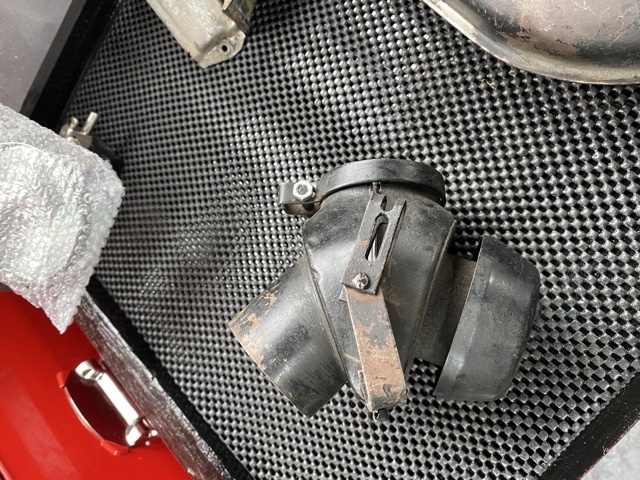 |
|
|
|
| dt4 |
Jun 27 2021, 09:01 AM
Post
#5
|
|
Senior Member Group: Members Posts: 503 Joined: 26-May 19 From: England Member No.: 23,161 Region Association: England |
Does anyone have a pair of clamps that fit the heater tubes pictured please
 |
|
|
|
| dt4 |
Jun 27 2021, 09:03 AM
Post
#6
|
|
Senior Member Group: Members Posts: 503 Joined: 26-May 19 From: England Member No.: 23,161 Region Association: England |
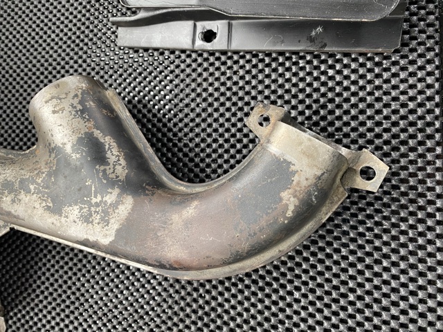
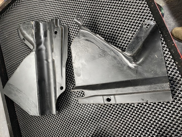
I am unable to figure out where these two shields fit, does anyone have a photo or diagram please
 |
|
|
|
| bdstone914 |
Jun 27 2021, 09:17 AM
Post
#7
|
|
bdstone914 Group: Members Posts: 4,537 Joined: 8-November 03 From: Riverside CA Member No.: 1,319 |
QUOTE(dt4 @ Jun 27 2021, 08:03 AM) I am unable to figure out where these two shields fit, does anyone have a photo or diagram please Those fit earlier cars. Are you back dating the system or sticking with the 75 heat exchangers. There are similar plates for the later cars. |
|
|
|
| bbrock |
Jun 27 2021, 09:27 AM
Post
#8
|
|
914 Guru Group: Members Posts: 5,269 Joined: 17-February 17 From: Montana Member No.: 20,845 Region Association: Rocky Mountains |
And for a pic showing how the parts you have attach, here is a pic of my car. Note that one of the attachment points is missing on this part (since replaced with a better one), but the plates attach to the heads and heat exchangers.
(IMG:http://www.914world.com/bbs2/uploads/post-20845-1616646080.jpg) |
|
|
|
| dt4 |
Jun 27 2021, 10:02 AM
Post
#9
|
|
Senior Member Group: Members Posts: 503 Joined: 26-May 19 From: England Member No.: 23,161 Region Association: England |
thank you for the picture that will help
I have a 75 1.8 so presuming the heat exchangers are correct for the year / engine I'll use your picture to check |
|
|
|
| euro911 |
Jun 27 2021, 08:54 PM
Post
#10
|
|
Retired & living the dream. God help me if I wake up! Group: Members Posts: 8,851 Joined: 2-December 06 From: So.Cal. & No.AZ (USA) Member No.: 7,300 Region Association: Southern California |
1975 & 1976 had a different exhaust system than what it appears you have. Guessing that a previous owner back-dated the exhaust system. That's not an issue if you have all the correct parts.
The caps on the heater valves face inward towards the middle of the engine bay, and the activation levers are on top. (IMG:http://www.914world.com/bbs2/uploads/post-7300-1332321907.jpg) Obviously there's a left side and a a right side (mirrored images). I wouldn't try to modify the offending one ... just source the correct one (as needed). The one you posted is the passenger side. (IMG:http://www.914world.com/bbs2/uploads/post-23161-1624806007.jpeg) Bruce Stone @bdstone914 might have the clamps you need (IMG:style_emoticons/default/confused24.gif) (IMG:http://www.914world.com/bbs2/uploads/post-23161-1624806106.jpeg) |
|
|
|
| Dave_Darling |
Jun 28 2021, 12:24 AM
Post
#11
|
|
914 Idiot Group: Members Posts: 14,991 Joined: 9-January 03 From: Silicon Valley / Kailua-Kona Member No.: 121 Region Association: Northern California |
Can you post a pic of what your exhaust system looks like?
Or at least, tell us if it has F-pipes attached to the heads that point forward, bolting to a piece that does a sharp 180-degree bend, and has a single pipe with a triangle-shaped exhaust flange? (One copy of each on each side, obviously.) Or do you have the type in the photos above? --DD |
|
|
|
| dt4 |
Jun 28 2021, 12:31 AM
Post
#12
|
|
Senior Member Group: Members Posts: 503 Joined: 26-May 19 From: England Member No.: 23,161 Region Association: England |
I will get the car back on the axle stands and take some photos
Thanks for the suggestions |
|
|
|
| StarBear |
Jun 28 2021, 09:25 AM
Post
#13
|
|
Senior Member Group: Members Posts: 1,910 Joined: 2-September 09 From: NJ Member No.: 10,753 Region Association: North East States |
QUOTE(dt4 @ Jun 27 2021, 11:00 AM) It appears to me that the pin for the flapper box on the driver side is in the wrong way and that the cable connector should be on the top not the bottom when the tubes are assembled? Could someone confirm please Can the pin be knocked out and assembled from the other side? Yes, the cables go on the top of each flapper unit; the flappers are a matched, mirrored (opposite) pair. |
|
|
|
| dt4 |
Jun 28 2021, 11:40 AM
Post
#14
|
|
Senior Member Group: Members Posts: 503 Joined: 26-May 19 From: England Member No.: 23,161 Region Association: England |
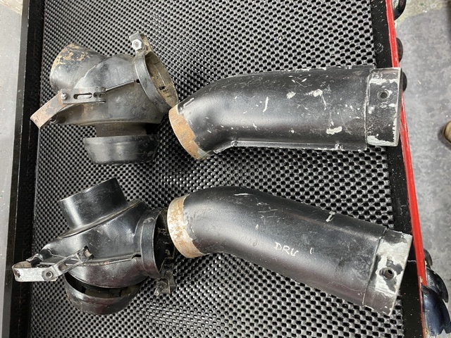
The flapper boxes and pipes
 |
|
|
|
| dt4 |
Jun 28 2021, 11:42 AM
Post
#15
|
|
Senior Member Group: Members Posts: 503 Joined: 26-May 19 From: England Member No.: 23,161 Region Association: England |
The heat exchanger on the driver side
 |
|
|
|
| dt4 |
Jun 28 2021, 11:43 AM
Post
#16
|
|
Senior Member Group: Members Posts: 503 Joined: 26-May 19 From: England Member No.: 23,161 Region Association: England |
The heat exchanger on the passenger side
 |
|
|
|
| StarBear |
Jun 28 2021, 12:29 PM
Post
#17
|
|
Senior Member Group: Members Posts: 1,910 Joined: 2-September 09 From: NJ Member No.: 10,753 Region Association: North East States |
QUOTE(dt4 @ Jun 28 2021, 01:40 PM) The flapper boxes and pipes Looks (?) like you have two of the same side (drivers?) boxes. |
|
|
|
| 914werke |
Jun 28 2021, 12:30 PM
Post
#18
|
|
"I got blisters on me fingers" Group: Members Posts: 10,141 Joined: 22-March 03 From: USofA Member No.: 453 Region Association: Pacific Northwest |
QUOTE(euro911 @ Jun 27 2021, 07:54 PM) 1975 & 1976 had a different exhaust system than what you have. Guessing that a PO back-dated the exhaust system. The caps on the heater valves face inward towards the middle of the engine bay, and the activation levers are on top. I typically flip the Valve side to side & orient the cables to the bottom for ease of service. (IMG:style_emoticons/default/idea.gif) |
|
|
|
| dt4 |
Jun 28 2021, 01:30 PM
Post
#19
|
|
Senior Member Group: Members Posts: 503 Joined: 26-May 19 From: England Member No.: 23,161 Region Association: England |
QUOTE(914werke @ Jun 28 2021, 07:30 PM) QUOTE(euro911 @ Jun 27 2021, 07:54 PM) 1975 & 1976 had a different exhaust system than what you have. Guessing that a PO back-dated the exhaust system. The caps on the heater valves face inward towards the middle of the engine bay, and the activation levers are on top. I typically flip the Valve side to side & orient the cables to the bottom for ease of service. (IMG:style_emoticons/default/idea.gif) it didnt look as thought the cable on the drivers side was long enough to reach the underside of the valve |
|
|
|
| dt4 |
Jun 28 2021, 01:32 PM
Post
#20
|
|
Senior Member Group: Members Posts: 503 Joined: 26-May 19 From: England Member No.: 23,161 Region Association: England |
QUOTE(StarBear @ Jun 28 2021, 07:29 PM) QUOTE(dt4 @ Jun 28 2021, 01:40 PM) The flapper boxes and pipes Looks (?) like you have two of the same side (drivers?) boxes. they are definitely different, the tube that connects to the flexi pipe on the firewall is a different length and angle |
|
|
|
|
1 User(s) are reading this topic (1 Guests and 0 Anonymous Users)
0 Members:

|
Lo-Fi Version | Time is now: 10th June 2024 - 01:25 AM |
Invision Power Board
v9.1.4 © 2024 IPS, Inc.