|
|
|
Porsche, and the Porsche crest are registered trademarks of Dr. Ing. h.c. F. Porsche AG.
This site is not affiliated with Porsche in any way. Its only purpose is to provide an online forum for car enthusiasts. All other trademarks are property of their respective owners. |
|
|

  |

| lmcchesney |
 Jan 28 2004, 06:26 AM Jan 28 2004, 06:26 AM
Post
#1
|
|
Member  Group: Members Posts: 488 Joined: 24-November 03 From: Ocala, Fl. Member No.: 1,381 Region Association: None |
Does anyone have ranges for Type IV cylinder head flows with customary pocket porting and port matching? I believe is about 200-225CFM at each port. Also, any data on the effect of large valves on the flow rates? Any data on port velocities?
Yes, I know that miminal changes can produce significant changes in flow. However, in reality, there is not a lot of variations in the P/P of these heads. Thanks, L. McChesney |
   |

 
|
| DNHunt |
Jan 28 2004, 08:05 AM
Post
#2
|
|
914 Wizard? No way. I got too much to learn. Group: Members Posts: 4,099 Joined: 21-April 03 From: Gig Harbor, WA Member No.: 598 |
Check over on Shop Talk Forums. I remember seeing some of that stuff. A buddy of Jake with the handle Ham is a head guy and seems real sharp. Somebody over there will have it.
Dave |
|
|
|
| SirAndy |
Jan 28 2004, 10:40 AM
Post
#3
|
|
Resident German Group: Admin Posts: 42,469 Joined: 21-January 03 From: Oakland, Kalifornia Member No.: 179 Region Association: Northern California |
QUOTE(lmcchesney @ Jan 28 2004, 04:26 AM) Also, any data on the effect of large valves on the flow rates? i have some of that at home, can post it later tonight ... Andy |
|
|
|
| lmcchesney |
Jan 28 2004, 01:39 PM
Post
#4
|
|
Member Group: Members Posts: 488 Joined: 24-November 03 From: Ocala, Fl. Member No.: 1,381 Region Association: None |
Thanks Dave.
Did a search on Shoptalkforums for author Ham. No results. However, there is some data by others. Seems to suggest 200-230CFM per intake port. Thanks Andy. I await your posting. Here's a sampling of our P/P job thus far: L. McChesney (IMG:style_emoticons/default/sad.gif) Still can't seem to post pictures. |
|
|
|
| Jake Raby |
Jan 28 2004, 02:18 PM
Post
#5
|
|
Engine Surgeon Group: Members Posts: 9,398 Joined: 31-August 03 From: Lost Member No.: 1,095 Region Association: South East States |
Don't worry about the intake..... the exhaust is the BIG issue.
|
|
|
|
| lmcchesney |
Jan 28 2004, 03:51 PM
Post
#6
|
|
Member Group: Members Posts: 488 Joined: 24-November 03 From: Ocala, Fl. Member No.: 1,381 Region Association: None |
Can you expand on that Jake?
Increased porting of the Exhaust ports? Use of CF's headers? Increase exhaust duration? All of the above? L. McChesney |
|
|
|
| r_towle |
Jan 28 2004, 03:54 PM
Post
#7
|
|
Custom Member Group: Members Posts: 24,705 Joined: 9-January 03 From: Taxachusetts Member No.: 124 Region Association: North East States |
Cant seem to upload spreadsheets....... <_< <_<
Error message telling me no bad boy go away... So try to decipher this Intake/Exhaust Diameter 1.88 1.5 47mm+- 37mm+- Valve lift/diameter L/D 0.05 0.1 0.15 0.2 0.25 0.3 Intake Valve Lift 0.094 0.188 0.282 0.376 0.47 0.564 Exhaust Valve Lift 0.075 0.15 0.225 0.3 0.375 0.45 Test Orifice Flow at 10" pressure 156.3 CFM Test Flow correction factor 0.98 Flow Range (cfm) 10 18 29 40 59 84 105 140 185 Corrected Range 9.8 17.64 28.4 39.2 57.8 82.3 102.9 137.2 181.3 Test Number 1 2 3 4 5 6 7 8 9 10 11 12 Port I or E Intake Intake Intake Intake Intake Intake Exhaust Exhaust Exhaust Exhaust Exhaust Exhaust Test Pressure 10 10 10 10 10 10 10 10 10 10 10 10 Valve Lift (in) 0.094 0.188 0.282 0.376 0.47 0.564 0.075 0.15 0.225 0.3 0.375 0.45 Corrected Flow range 39.2 57.8 102.9 102.9 102.9 102.9 28.4 39.2 57.8 57.8 82.3 82.3 Flow meter 0.78 0.95 0.735 0.83 0.875 0.885 0.62 0.805 0.685 0.825 0.665 0.715 Chart CFM (Line 17*Line16) 30.58 54.91 75.63 85.4 90 91.1 17.6 31.6 39.6 47.7 54.7 58.9 Temp Difference 25 25 25 30 35 35 15 30 30 30 30 35 Temp Diff Factor 0.981 0.981 0.981 0.977 0.973 0.973 1.012 102.3 1.023 1.023 1.023 1.027 Corr test CFM 29.9 53.9 74.2 83.4 87.6 88.6 17.8 32.3 40.5 48.8 55.9 60.5 Corr CFM 11.1 19.9 27.5 30.9 32.5 32.8 10.5 19.1 23.9 28.9 33.1 35.8 Potential CFM 13.6 27.3 41 47 50.2 52.3 13.6 27.3 41 54.9 58.5 60.1 % Flow rating 82 73 67 65 65 62 77 70 58 53 57 60 R |
|
|
|
| r_towle |
Jan 28 2004, 03:56 PM
Post
#8
|
|
Custom Member Group: Members Posts: 24,705 Joined: 9-January 03 From: Taxachusetts Member No.: 124 Region Association: North East States |
Looks like if you copy all of it and put it in a spread sheet it will make sense...
Sorry, not my board... XLS files are not permitted... (IMG:style_emoticons/default/headbang.gif) |
|
|
|
| Bleyseng |
Jan 28 2004, 04:16 PM
Post
#9
|
|
Aircooled Baby! Group: Members Posts: 13,037 Joined: 27-December 02 From: Seattle, Washington (for now) Member No.: 24 Region Association: Pacific Northwest |
Do it as a screen shot then we can look at it.
Geoff |
|
|
|
| r_towle |
Jan 28 2004, 04:32 PM
Post
#10
|
|
Custom Member Group: Members Posts: 24,705 Joined: 9-January 03 From: Taxachusetts Member No.: 124 Region Association: North East States |
try this
Attached thumbnail(s) 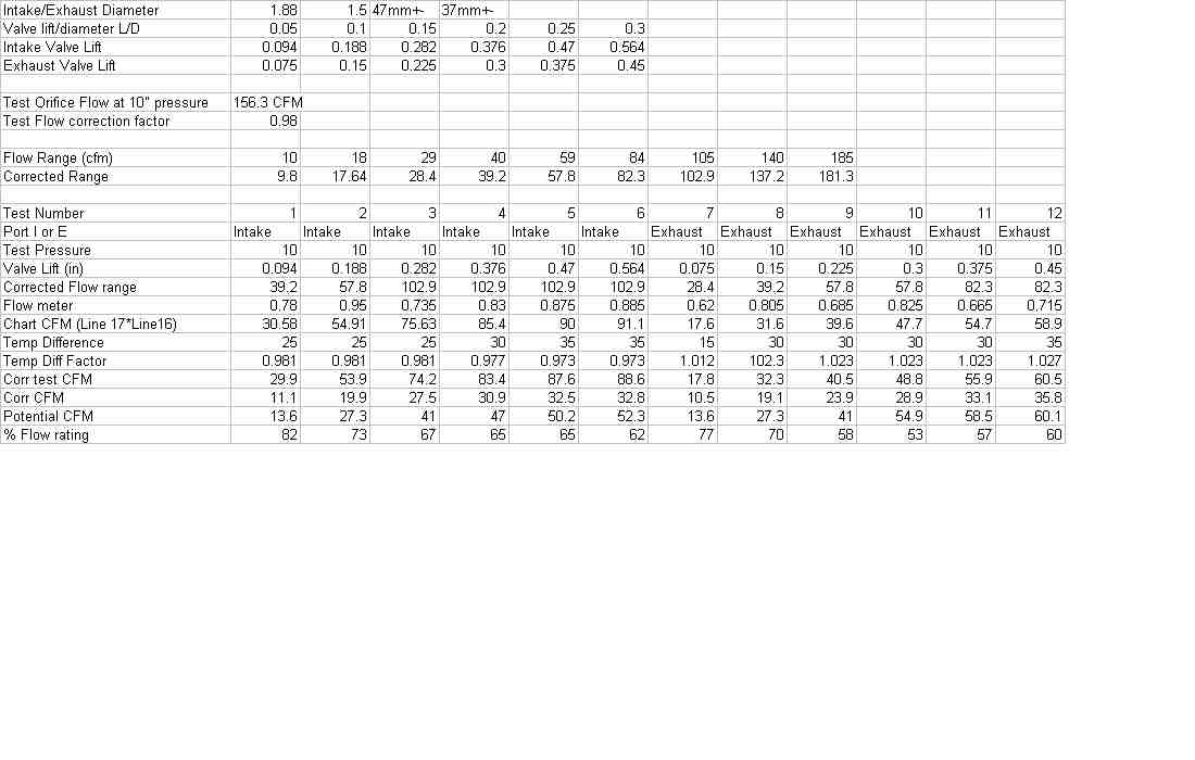
|
|
|
|
| lmcchesney |
Jan 28 2004, 07:02 PM
Post
#11
|
|
Member Group: Members Posts: 488 Joined: 24-November 03 From: Ocala, Fl. Member No.: 1,381 Region Association: None |
Thanks R_Towle
Am I reading this right. 74mm intake at .564 lift has a corrected flow of 88.6CFM? Can you provide the amount of head preperation done? Valves 47 x 37mm Was the exhaust boss removed? Is the head port matched to 2.0L or 35mm intake 30mm exhaust? How much bowl porting done? Was the intakes cleaned to 60 grit? Thanks for the informaiton. L. McChesney |
|
|
|
| Jake Raby |
Jan 29 2004, 10:37 AM
Post
#12
|
|
Engine Surgeon Group: Members Posts: 9,398 Joined: 31-August 03 From: Lost Member No.: 1,095 Region Association: South East States |
Stock intake ports flow over 200 CFM... Getting over 150 out the exhaust is a chore..
Thats why we use split duration- and alot of it! The more work you do to the intake- the worse the ratio of intake/ exhaust is.... Most of my heads get no port work on the intake. Flowbenches are great but they are dealing with air that has not gobne through a burning process already.. They give base line numbers- but don't live by one. I have not flowed a set of heads in over a year on my bench. |
|
|
|
| lmcchesney |
Jan 29 2004, 12:36 PM
Post
#13
|
|
Member Group: Members Posts: 488 Joined: 24-November 03 From: Ocala, Fl. Member No.: 1,381 Region Association: None |
Thanks Jake,
That is what we are thinking. The Intake ports have had the protruding seams smoothed and ports matched only and polished to 60grit smoothness. The exhaust ports have had the work with removal of the boss and opening of the port sides while keeping the short radius smoothed but not changed. The port has also been patched. Denny McNutt, Autocraft Engines, also believes stock heads flow at 200-225CFM and that is the data we have been using in the simulators. The crux seems to find a cam grind with about Intake dur of 260-265 but have an exhaust dur of 270-275. By the way, Sean Rupp says hello and is still working on his Type IV. Thanks again, L. McChesney(Andrew, Eric and David) |
|
|
|
| Brett W |
Jan 29 2004, 06:16 PM
Post
#14
|
|
Advanced Member Group: Members Posts: 2,859 Joined: 17-September 03 From: huntsville, al Member No.: 1,169 Region Association: None |
The last set of heads I did were some 2.0 heads with stock valve sizes 42int 37 exh. I managed to get something like 190 on the intake side and something like 145 on the exhaust side. I wasn't happy with them but they will work well for the application. I figure I could have broken 200 on the intakes with 7mm valves and 150 on the exhaust, but the exhaust will definitley take a bunch of research to help them. I am trying to build a flow bench so I can do that shortly.
|
|
|
|
| lmcchesney |
Jan 30 2004, 04:51 AM
Post
#15
|
|
Member Group: Members Posts: 488 Joined: 24-November 03 From: Ocala, Fl. Member No.: 1,381 Region Association: None |
Thanks everyone,
I pulled out the data from the Grassroots Motorsports article 8(6): 114 Dec 2001 on the head preperation they done and what the flow results were. Very similar. Intake flow at .5 went from 175 to 188(+7%) and exhaust at .5 from 129 to 157(+22%) with a final E:I of 84%. On the desktop dyno with a cam of IVD 262° IVO 12°BTDC IVC 70°ABDC and EVD 275° EVO 70.5°BBDC EVC 24.5 with a seperation of 116° and a timing of -5°. Any thoughts? Brent, I found an article on making your own flow bench, using six vacum cleaner motors and pitots for flow measurments. Cost estimates $800 with $600 in vacum cleaner motors. It is, "Flow Bench" by Michael Doty but I don't remember where it is from. With the images, it is too big for attachment. If you email me, I can attach it to the email. Thanks, L. McChesney lamcchesney@netzero.net |
|
|
|
| Jake Raby |
Jan 30 2004, 09:07 AM
Post
#16
|
|
Engine Surgeon Group: Members Posts: 9,398 Joined: 31-August 03 From: Lost Member No.: 1,095 Region Association: South East States |
Those intakes are flowing WAY too much! Sounds like a "Typical" head job.....
Don't mean to be negative, but that throws the entire combination so far off that you can never get the engine to respond to tuning measures! |
|
|
|
| cnavarro |
Jan 30 2004, 10:58 AM
Post
#17
|
|
Cylinder Guru Group: Members Posts: 472 Joined: 30-December 02 From: Chicagoland! Member No.: 49 Region Association: None |
There is a past thread where I uploaded a flow chart for my 42 x 38 specials :-) I have back in the office flow numbers for a dozen different head configurations that I can post if you guys want them. Here's the link to the thread:
http://www.914world.com/bbs2/index.php?act...st=0&hl=nickies Charles Navarro LN Engineering http://www.LNengineering.com Aircooled Precision Performance |
|
|
|
| Brett W |
Jan 30 2004, 12:00 PM
Post
#18
|
|
Advanced Member Group: Members Posts: 2,859 Joined: 17-September 03 From: huntsville, al Member No.: 1,169 Region Association: None |
I have seen the article on the flow bench. Not impressed. If you want to flow weedeater heads that might do the job. If you want to do some serious flow research you need to be testing at a minimum of 28 inches of water. I have a three hp motor with a large cetrifugal blower attached that I am going to use for my basis. I suspect the motor will be a little small. I would like to see a 10 hp motor but I didn't have one laying around.
Check out the bench Smokey used to use. Powered by a 100hp electric motor. http://www.smokeyyunick.com/ look at the ebay items section. |
|
|
|
| Jake Raby |
Jan 30 2004, 01:39 PM
Post
#19
|
|
Engine Surgeon Group: Members Posts: 9,398 Joined: 31-August 03 From: Lost Member No.: 1,095 Region Association: South East States |
Is that an implication that I have inferior equipment??
I don't need to "Impress" anyone! Our works speaks for its self- argue with that Fact is all I use that bench for is to measure the splits between ports, I don't even worry about whole numbers. I already have 95% of all my head combinations matched to my engine combinations. As far as I'm concerned trying to flow heads for days is a waste of time anyway! it just gives you and IDEA on what to do...(how the hell do you think I designed 32 different split duration cams?) The only way to prove it- is to build it. Unless someone builds as many engines as we do and make small changes and compare the results you will never know what you head numbers did - if you wasted all that time or not. In my experience, the flow bench is basically a huge waste of time, just something to advertise with. (IMG:style_emoticons/default/bs.gif) If I need a bench, my buddy is the shope Foreman over at Ernie Elliot Inc... They have 3 different benchs and the smallest one has 9 motors, biggest one has 27. It flows enough to test heads that have SEVEN POUNDS of aluminum removed from their ports.... Guess what else they have- a superflow 120 just like mine, and its not collecting dust either! Hell I wouldn't even have one if I had not TRADED for it! It sat here for a year before I ever plugged it in. Word of advise- Don't ever doubt me or my work, and we'll get along just fine. If you do doubt me you might just find yourself with an ultimate challenge of proving me wrong- better bring your supper with ya when you take that one on, and be ready for 3 days without sleep just to keep up with me!! We all have our own ideas, I respect yours, just don't imply that I'm working with junk- That REALLY pisses me off. |
|
|
|
| SirAndy |
Jan 30 2004, 01:51 PM
Post
#20
|
|
Resident German Group: Admin Posts: 42,469 Joined: 21-January 03 From: Oakland, Kalifornia Member No.: 179 Region Association: Northern California |
QUOTE(Jake Raby @ Jan 30 2004, 11:39 AM) Word of advise- Don't ever doubt me or my work thanks for the laugh (IMG:style_emoticons/default/laugh.gif) now go back and build engines, LOL Andy PS: finally, a pissing match where i'm only a spectator ... |
|
|
|
|
1 User(s) are reading this topic (1 Guests and 0 Anonymous Users)
0 Members:

|
Lo-Fi Version | Time is now: 2nd April 2026 - 04:41 PM |
Invision Power Board
v9.1.4 © 2026 IPS, Inc.