|
|
|
Porsche, and the Porsche crest are registered trademarks of Dr. Ing. h.c. F. Porsche AG.
This site is not affiliated with Porsche in any way. Its only purpose is to provide an online forum for car enthusiasts. All other trademarks are property of their respective owners. |
|
|


| Highland |
 Dec 17 2013, 12:26 PM Dec 17 2013, 12:26 PM
Post
#1
|
|
Senior Member  Group: Members Posts: 513 Joined: 8-August 11 From: San Diego, CA Member No.: 13,418 Region Association: Southern California |
I started setting up the valve train for a 9590 cam with 0.426" lift for both exhaust and intake. I took some pictures at half lift and like to get some verification on this is what it's suppose to look like. I know the drawn in lines are not completely valid cause the picture is not perfectly square form the side.
Also RAT specifies to be within +/-5% of cam lift. Is within 5% cylinder to cylinder also okay? If not, what is a good target? 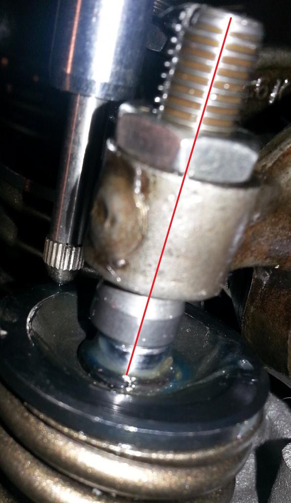 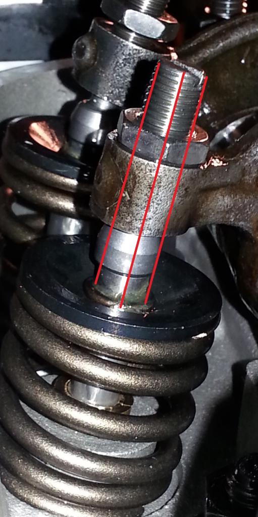 |
   |

 
|
  |
Replies(1 - 5)
| nathansnathan |
Dec 17 2013, 12:34 PM
Post
#2
|
|
Senior Member Group: Members Posts: 1,052 Joined: 31-May 10 From: Laguna Beach, CA Member No.: 11,782 Region Association: None |
It looks like the adjuster isn't out enough. If it binds on the rocker, it's bad. Actually looks like the rockers aren't decked enough to run those adjusters.
I've always tried to get them the same as each other as it will affect adjusting them/synching them. |
|
|
|
| Highland |
Dec 17 2013, 04:23 PM
Post
#3
|
|
Senior Member Group: Members Posts: 513 Joined: 8-August 11 From: San Diego, CA Member No.: 13,418 Region Association: Southern California |
Thanks for the input. I've got at least one turn before the adjusters bottom out against the rocker. Is that enough? A mill is not readily available, but of course I'll take down more if I have too. Took down .060 when I had them done.
Any opinions on how the geometry looks at 1/2 lift? Also RAT specifies <0.006" play along the rocker shaft and to sand down the solid spacer to specification. Would replacing the provided washers with shims (instead of sanding the spacer) be okay or are those washers special? |
|
|
|
| Mark Henry |
Dec 17 2013, 05:26 PM
Post
#4
|
|
that's what I do! Group: Members Posts: 20,065 Joined: 27-December 02 From: Port Hope, Ontario Member No.: 26 Region Association: Canada |
If you removed .060 from the bottom of the adjuster screw hole now radius (grind, countersink) the hole so the foot swivels freely.
|
|
|
|
| Jake Raby |
Dec 17 2013, 07:03 PM
Post
#5
|
|
Engine Surgeon Group: Members Posts: 9,394 Joined: 31-August 03 From: Lost Member No.: 1,095 Region Association: South East States |
QUOTE(Mark Henry @ Dec 17 2013, 03:26 PM)  If you removed .060 from the bottom of the adjuster screw hole now radius (grind, countersink) the hole so the foot swivels freely. Yep. And it looks like the geometry is pretty close in these pics. |
|
|
|
| gothspeed |
Dec 17 2013, 08:10 PM
Post
#6
|
|
Senior Member Group: Members Posts: 1,539 Joined: 3-February 09 From: SoCal Member No.: 10,019 Region Association: None |
Looks good (IMG:style_emoticons/default/smile.gif)
|
|
|
|
|
1 User(s) are reading this topic (1 Guests and 0 Anonymous Users)
0 Members:

|
Lo-Fi Version | Time is now: 29th May 2024 - 05:43 AM |
Invision Power Board
v9.1.4 © 2024 IPS, Inc.