|
|
|
Porsche, and the Porsche crest are registered trademarks of Dr. Ing. h.c. F. Porsche AG.
This site is not affiliated with Porsche in any way. Its only purpose is to provide an online forum for car enthusiasts. All other trademarks are property of their respective owners. |
|
|


| motorvated |
 Apr 22 2018, 03:03 PM Apr 22 2018, 03:03 PM
Post
#1
|
|
Member  Group: Members Posts: 281 Joined: 13-February 13 From: Colorado Member No.: 15,519 Region Association: Rocky Mountains |
The three white wires going to the connector on the bottom of the Throttle Body on my 1975 1.8 L Jet motor have broken. I need to know what pin on the ECU connector each goes to. So far continuity check reveals one wire going to Pin 1, and another going to Pin 16. Third wire going to Pin 17. So which position on the connector does each wire go to? Retaining wire and two outboard grooves are on the bottom, single central groove on the top. Anybody know?
Thanks. 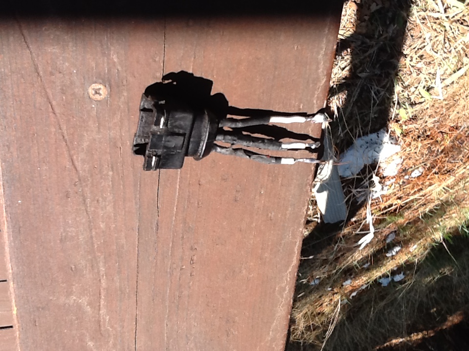 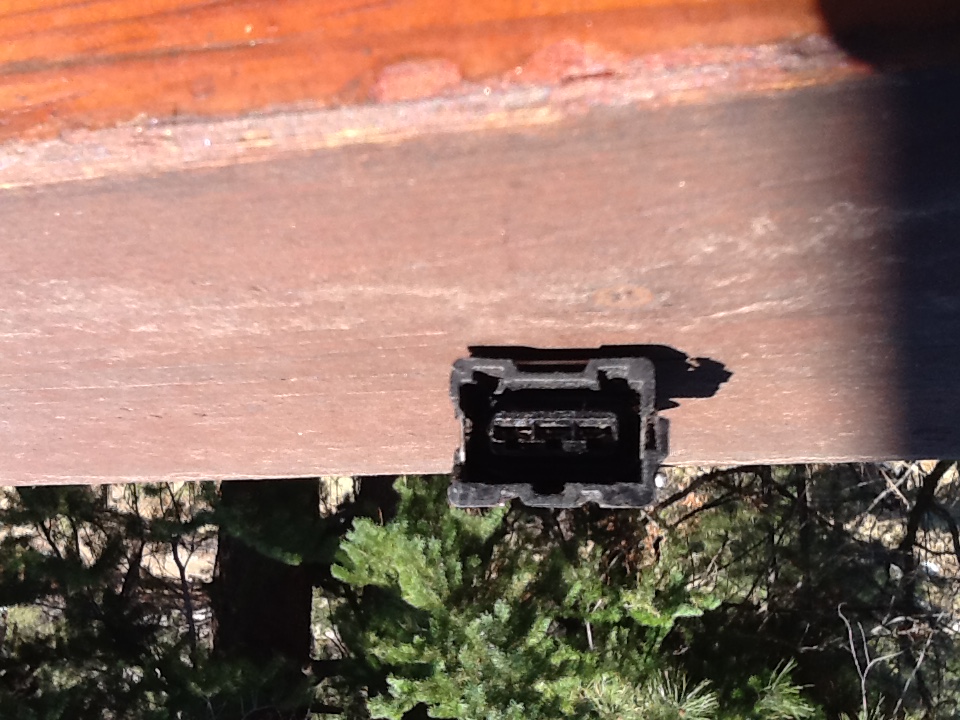 |
   |

 
|
  |
Replies(1 - 4)
| JeffBowlsby |
Apr 22 2018, 03:17 PM
Post
#2
|
|
914 Wiring Harnesses Group: Members Posts: 8,524 Joined: 7-January 03 From: San Ramon CA Member No.: 104 Region Association: None |
See the harness diagram and schematic on my harness website. If you are getting those circuit #s in the continuity check you have internal shorts in your harness.
|
 |
|
| motorvated |
Apr 22 2018, 04:43 PM
Post
#3
|
|
Member Group: Members Posts: 281 Joined: 13-February 13 From: Colorado Member No.: 15,519 Region Association: Rocky Mountains |
QUOTE(Jeff Bowlsby @ Apr 22 2018, 03:17 PM)  See the harness diagram and schematic on my harness website. If you are getting those circuit #s in the continuity check you have internal shorts in your harness. Thank you Jeff. I read the PIN numbers upside down, counting from the top not the bottom. So my pins are at 18, 2, and 3, which is consistent with the diagram on your website. I'm saving up for a new FI harness, as mine is brittle with connections that are marginal at best. Thanks for the help. One more quick question for Jeff. The diagram on your webpage shows the Throttle Position Switch with the three PIN numbers. Is that actually showing the connector to the switch, looking at it head on? |
|
|
|
| motorvated |
Apr 22 2018, 04:55 PM
Post
#4
|
|
Member Group: Members Posts: 281 Joined: 13-February 13 From: Colorado Member No.: 15,519 Region Association: Rocky Mountains |
QUOTE(motorvated @ Apr 22 2018, 04:43 PM) QUOTE(Jeff Bowlsby @ Apr 22 2018, 03:17 PM) See the harness diagram and schematic on my harness website. If you are getting those circuit #s in the continuity check you have internal shorts in your harness. Thank you Jeff. I read the PIN numbers upside down, counting from the top not the bottom. So my pins are at 18, 2, and 3, which is consistent with the diagram on your website. I'm saving up for a new FI harness, as mine is brittle with connections that are marginal at best. Thanks for the help. One more quick question for Jeff. The diagram on your webpage shows the Throttle Position Switch with the three PIN numbers. Is that actually showing the connector to the switch, looking at it head on? |
|
|
|
| JeffBowlsby |
Apr 22 2018, 05:31 PM
Post
#5
|
|
914 Wiring Harnesses Group: Members Posts: 8,524 Joined: 7-January 03 From: San Ramon CA Member No.: 104 Region Association: None |
QUOTE(motorvated @ Apr 22 2018, 03:43 PM) QUOTE(Jeff Bowlsby @ Apr 22 2018, 03:17 PM) See the harness diagram and schematic on my harness website. If you are getting those circuit #s in the continuity check you have internal shorts in your harness. Thank you Jeff. I read the PIN numbers upside down, counting from the top not the bottom. So my pins are at 18, 2, and 3, which is consistent with the diagram on your website. I'm saving up for a new FI harness, as mine is brittle with connections that are marginal at best. Thanks for the help. One more quick question for Jeff. The diagram on your webpage shows the Throttle Position Switch with the three PIN numbers. Is that actually showing the connector to the switch, looking at it head on? Yes, the connector housing orientation is as if you are looking a the business end of it. The circuits are numbered on the ECU connector housing, but you need to slide the cover off to see them. |
|
|
|
|
1 User(s) are reading this topic (1 Guests and 0 Anonymous Users)
0 Members:

|
Lo-Fi Version | Time is now: 1st June 2024 - 08:26 PM |
Invision Power Board
v9.1.4 © 2024 IPS, Inc.