|
|
|
Porsche, and the Porsche crest are registered trademarks of Dr. Ing. h.c. F. Porsche AG.
This site is not affiliated with Porsche in any way. Its only purpose is to provide an online forum for car enthusiasts. All other trademarks are property of their respective owners. |
|
|


| Tdskip |
 May 1 2019, 08:43 PM May 1 2019, 08:43 PM
Post
#1
|
|
Advanced Member  Group: Members Posts: 3,737 Joined: 1-December 17 From: soCal Member No.: 21,666 Region Association: None |
Or, in other words, where is a first time engine builder most likely to go wrong?
|
   |

 
|
  |
Replies(1 - 19)
| Mark Henry |
May 1 2019, 08:49 PM
Post
#2
|
|
that's what I do! Group: Members Posts: 20,065 Joined: 27-December 02 From: Port Hope, Ontario Member No.: 26 Region Association: Canada |
Main bearing pinched on a dowel pin.
Trying to cheap out on headwork. That one part you didn't replace. Thinking you know more about cooling tin, flaps, T-stat, etc., than VW/Porsche.... |
|
|
|
| Tdskip |
May 1 2019, 09:17 PM
Post
#3
|
|
Advanced Member Group: Members Posts: 3,737 Joined: 1-December 17 From: soCal Member No.: 21,666 Region Association: None |
That’s a good starting list-thanks
|
|
|
|
| Superhawk996 |
May 2 2019, 05:50 AM
Post
#4
|
|
914 Guru Group: Members Posts: 7,253 Joined: 25-August 18 From: Woods of N. Idaho Member No.: 22,428 Region Association: Galt's Gulch |
QUOTE(Mark Henry @ May 1 2019, 10:49 PM)  Thinking you know more about cooling tin, flaps, T-stat, etc., than VW/Porsche.... Love it -- (IMG:style_emoticons/default/biggrin.gif) Can't tell you how frustrating it is to see so many 914's that have had cooling flaps pulled over the years. |
|
|
|
| Mblizzard |
May 2 2019, 06:59 AM
Post
#5
|
|
Advanced Member Group: Members Posts: 3,033 Joined: 28-January 13 From: Knoxville Tn Member No.: 15,438 Region Association: South East States |
Incorrect alignment of cam and crank timing marks.
Breaking the eyelet off oil pickup when installing the bolt through the case. Not checking deck height and confirming compression ratio. Not lapping the cylinders to the heads. Not using correct sealant for case. Improper installation of oil cooler seals = leak Incorrect setting of the crank end play. Not surfacing pressure plate mounting surface the same amount as the clutch surface. Not that I have ever done any of those things. (IMG:style_emoticons/default/shades.gif) |
|
|
|
| Tdskip |
May 2 2019, 07:24 AM
Post
#6
|
|
Advanced Member Group: Members Posts: 3,737 Joined: 1-December 17 From: soCal Member No.: 21,666 Region Association: None |
I won’t ask how you know Mike.
Grin. |
|
|
|
| bbrock |
May 2 2019, 07:35 AM
Post
#7
|
|
914 Guru Group: Members Posts: 5,269 Joined: 17-February 17 From: Montana Member No.: 20,845 Region Association: Rocky Mountains |
QUOTE(Mblizzard @ May 2 2019, 06:59 AM) Not surfacing pressure plate mounting surface the same amount as the clutch surface. Is grinding the ridges off the flywheel bolts a suitable work around for this? When I had my flywheel resurfaced decades ago, I asked them to surface the mounting hub to match but I don't think they did it. I decided to grind the bolts to be sure I have clearance but haven't run the engine yet. Is that going to bite me in the butt? Also, it's been a long time, but it seemed like installing the distributor gear was a little tricky. |
|
|
|
| Mblizzard |
May 2 2019, 08:00 AM
Post
#8
|
|
Advanced Member Group: Members Posts: 3,033 Joined: 28-January 13 From: Knoxville Tn Member No.: 15,438 Region Association: South East States |
QUOTE(bbrock @ May 2 2019, 05:35 AM) QUOTE(Mblizzard @ May 2 2019, 06:59 AM) Not surfacing pressure plate mounting surface the same amount as the clutch surface. Is grinding the ridges off the flywheel bolts a suitable work around for this? When I had my flywheel resurfaced decades ago, I asked them to surface the mounting hub to match but I don't think they did it. I decided to grind the bolts to be sure I have clearance but haven't run the engine yet. Is that going to bite me in the butt? Also, it's been a long time, but it seemed like installing the distributor gear was a little tricky. I have seen that done but I think that is due to the removal of too much material from the surface and the bolts extend above the flywheel surface. If you fail to machine both surfaces clutch slippage will be a problem. If so much material was removed that you had to grind the bolts you might want to look at it again. I grade on a good bad scale. Anytime you have to modify bolts to fit stock parts it is likely bad! |
|
|
|
| Tdskip |
May 2 2019, 08:19 AM
Post
#9
|
|
Advanced Member Group: Members Posts: 3,737 Joined: 1-December 17 From: soCal Member No.: 21,666 Region Association: None |
I am assuming the do/don't on this is all written up somewhere?
For those that have also rebuild a more conventional water cooled engine, say inline 4 or 6, how much harder / easier are the Type 4 rebuild? Great discussion, hope it helps others thinking about this too. |
|
|
|
| bbrock |
May 2 2019, 08:21 AM
Post
#10
|
|
914 Guru Group: Members Posts: 5,269 Joined: 17-February 17 From: Montana Member No.: 20,845 Region Association: Rocky Mountains |
QUOTE(Mblizzard @ May 2 2019, 08:00 AM) QUOTE(bbrock @ May 2 2019, 05:35 AM) QUOTE(Mblizzard @ May 2 2019, 06:59 AM) Not surfacing pressure plate mounting surface the same amount as the clutch surface. Is grinding the ridges off the flywheel bolts a suitable work around for this? When I had my flywheel resurfaced decades ago, I asked them to surface the mounting hub to match but I don't think they did it. I decided to grind the bolts to be sure I have clearance but haven't run the engine yet. Is that going to bite me in the butt? Also, it's been a long time, but it seemed like installing the distributor gear was a little tricky. I have seen that done but I think that is due to the removal of too much material from the surface and the bolts extend above the flywheel surface. If you fail to machine both surfaces clutch slippage will be a problem. If so much material was removed that you had to grind the bolts you might want to look at it again. I grade on a good bad scale. Anytime you have to modify bolts to fit stock parts it is likely bad! Whoops! Looks like a misread what you were saying. Yes, when my flywheel was surfaced, they took .027 off the friction surface and a matching amount off the outer ring where the pressure plate mounts. I mistakenly thought you were talking about the center hub where the flywheel bolts to the crank. That's what may not have been surfaced so I ground the ridges on the bolts just to make sure they don't hit the friction disc. Disregard my question. Carry on. (IMG:style_emoticons/default/smile.gif) |
|
|
|
| jcd914 |
May 2 2019, 10:12 AM
Post
#11
|
|
Advanced Member Group: Members Posts: 2,096 Joined: 7-February 08 From: Sacramento, CA Member No.: 8,684 Region Association: Northern California |
QUOTE(bbrock @ May 2 2019, 07:21 AM) I mistakenly thought you were talking about the center hub where the flywheel bolts to the crank. This is not something that should be machined down when the flywheel is surfaced. It is a structural part of the flywheel and should be left alone. If enough material has been removed from the clutch surface of the flywheel the clutch disc can contact the flywheel bolts. Really that means the flywheel is past its wear limit and should be replaced but I have seem many the have had the ridges on the flywheel bold ground down to add clearance. I have not seen a failure related to the specific modification. There is a diagram with the machining specs for the 914/6 flywheel that seems to be the accepted standard for the 4cly flywheel as well. I don't think the bolts need to be ground if the flywheel is kept within the limits in the diagram. I don't have a copy of the diagram handy or I would post it here. Jim |
|
|
|
| Tdskip |
May 2 2019, 10:17 AM
Post
#12
|
|
Advanced Member Group: Members Posts: 3,737 Joined: 1-December 17 From: soCal Member No.: 21,666 Region Association: None |
So really only an issue if the fly wheel has been lightened? I suppose given who knows what has happened to our cars in the last 40+ years it’s probably worth not assuming anything .
|
|
|
|
| rhodyguy |
May 2 2019, 10:26 AM
Post
#13
|
|
Chimp Sanctuary NW. Check it out. Group: Members Posts: 22,249 Joined: 2-March 03 From: Orion's Bell. The BELL! Member No.: 378 Region Association: Galt's Gulch |
The run out on the fly wheel must be taken in to account prior to machining. You need to weigh the bolts when grinding them down. Kind of time consuming. The center area has a critical dimension. Hines has the numbers for this procedure.
|
|
|
|
| VaccaRabite |
May 2 2019, 10:46 AM
Post
#14
|
|
En Garde! Group: Admin Posts: 13,765 Joined: 15-December 03 From: Dallastown, PA Member No.: 1,435 Region Association: MidAtlantic Region |
Echoing what Mark said.
The dowel pin munching a main bearing is a prime newbie error. It certainly got me. And when you do it the bearing is trashed - no chance to fix it. Buy a new set of bearings... The other issue is making sure you have proper clearances for your bearings when everything is tightened down. And if you don't, knowing how to fix it. Zach |
|
|
|
| worn |
May 2 2019, 11:22 AM
Post
#15
|
|
Winner of the Utah Twisted Joint Award Group: Members Posts: 3,492 Joined: 3-June 11 From: Madison, WI Member No.: 13,152 Region Association: Upper MidWest |
QUOTE(Tdskip @ May 1 2019, 06:43 PM) Or, in other words, where is a first time engine builder most likely to go wrong? I didn't realize just how important the main case bolt rubber seals are. The bolts go through oil galleys, and have to hold back full oil pressure. I tried to reuse the old ones and now I have lots of weeping oil leaks. Everything has to fit close and tight to seal in the oil. |
|
|
|
| Mblizzard |
May 2 2019, 11:28 AM
Post
#16
|
|
Advanced Member Group: Members Posts: 3,033 Joined: 28-January 13 From: Knoxville Tn Member No.: 15,438 Region Association: South East States |
QUOTE(jcd914 @ May 2 2019, 08:12 AM) QUOTE(bbrock @ May 2 2019, 07:21 AM) I mistakenly thought you were talking about the center hub where the flywheel bolts to the crank. This is not something that should be machined down when the flywheel is surfaced. It is a structural part of the flywheel and should be left alone. If enough material has been removed from the clutch surface of the flywheel the clutch disc can contact the flywheel bolts. Really that means the flywheel is past its wear limit and should be replaced but I have seem many the have had the ridges on the flywheel bold ground down to add clearance. I have not seen a failure related to the specific modification. There is a diagram with the machining specs for the 914/6 flywheel that seems to be the accepted standard for the 4cly flywheel as well. I don't think the bolts need to be ground if the flywheel is kept within the limits in the diagram. I don't have a copy of the diagram handy or I would post it here. Jim 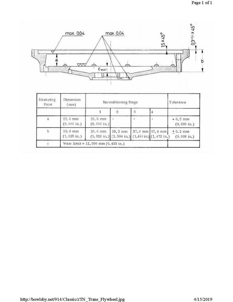 |
|
|
|
| bbrock |
May 2 2019, 11:38 AM
Post
#17
|
|
914 Guru Group: Members Posts: 5,269 Joined: 17-February 17 From: Montana Member No.: 20,845 Region Association: Rocky Mountains |
QUOTE(jcd914 @ May 2 2019, 10:12 AM) QUOTE(bbrock @ May 2 2019, 07:21 AM) I mistakenly thought you were talking about the center hub where the flywheel bolts to the crank. There is a diagram with the machining specs for the 914/6 flywheel that seems to be the accepted standard for the 4cly flywheel as well. I don't think the bolts need to be ground if the flywheel is kept within the limits in the diagram. I don't have a copy of the diagram handy or I would post it here. Jim Ah, Mike beat me to it. Is this the diagram you reference? It's the one I gave the machinist who resurfaced my flywheel anyway. (IMG:http://www.914world.com/bbs2/uploads_offsite/uploads.tapatalk-cdn.com-20845-1556818732.1.jpg) Looking at it again, I may have been misinterpreting all these years. I took it to mean you would have to machine the center hub to maintain dimension C, but now I see it is probably just saying if machining the other two surfaces puts C out of tolerance, your flywheel is no good. I guess the machinists followed the diagram I gave them after all. (IMG:style_emoticons/default/cheer.gif) |
|
|
|
| Superhawk996 |
May 2 2019, 11:59 AM
Post
#18
|
|
914 Guru Group: Members Posts: 7,253 Joined: 25-August 18 From: Woods of N. Idaho Member No.: 22,428 Region Association: Galt's Gulch |
is it just me misreading? I don't think dimension "b" is changing with machining. It would amount to taking material off the ring gear.
material would be taken off the friction surface and an equal amount off the ledge that is below b. This dimension is show as "a". This maintains the same relationship between the friction surface and the ledge surface that the pressure plate mounts. Again this is dimension 'a'. I see no reason dimension b would ever change. What am I missing? |
|
|
|
| rhodyguy |
May 2 2019, 12:01 PM
Post
#19
|
|
Chimp Sanctuary NW. Check it out. Group: Members Posts: 22,249 Joined: 2-March 03 From: Orion's Bell. The BELL! Member No.: 378 Region Association: Galt's Gulch |
I was under the impression that 'C' is the minimum. Dependent what C is on a new one there might be room for dressing it down. Do I have that correctly Jeff?
|
|
|
|
| Superhawk996 |
May 2 2019, 12:03 PM
Post
#20
|
|
914 Guru Group: Members Posts: 7,253 Joined: 25-August 18 From: Woods of N. Idaho Member No.: 22,428 Region Association: Galt's Gulch |
@bbrock
To Brent's point, as long as the 11mm dimension 'C' doesn't go below 11mm you'll have room for the flywheel bolt heads. I just measured a bolt head and it is 9.2mm from shoulder to top of the head. |
|
|
|
|
1 User(s) are reading this topic (1 Guests and 0 Anonymous Users)
0 Members:

|
Lo-Fi Version | Time is now: 31st July 2025 - 03:36 PM |
Invision Power Board
v9.1.4 © 2025 IPS, Inc.