|
|
|
Porsche, and the Porsche crest are registered trademarks of Dr. Ing. h.c. F. Porsche AG.
This site is not affiliated with Porsche in any way. Its only purpose is to provide an online forum for car enthusiasts. All other trademarks are property of their respective owners. |
|
|


| ThinAir |
 Oct 20 2020, 11:49 PM Oct 20 2020, 11:49 PM
Post
#1
|
|
Best friends  Group: Members Posts: 2,543 Joined: 4-February 03 From: Flagstaff, AZ Member No.: 231 Region Association: Southwest Region |
Electrical systems & I are not friends, so I have little experience with this. I don't know how to interpret these readings or how the range changes what I'm seeing. Searching has turned up lots of stuff that seems to assume that you know this. TIA for the advice.
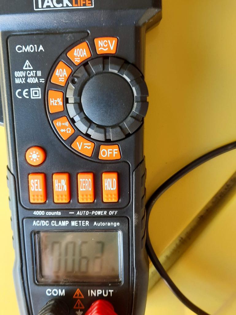 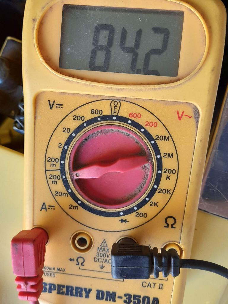 Both of these readings were taken with the circuit in the same state. (I thought I had one when set to the 400A range). |
   |

 
|
  |
Replies(1 - 14)
| tom.esh |
Oct 21 2020, 04:52 AM
Post
#2
|
|
Member Group: Members Posts: 63 Joined: 6-March 14 From: Canton Ohio Member No.: 17,083 Region Association: North East States |
Top display looks to be .63 amps. Bottom display is 82.4 milli amps. The 400A scale is not a good choice for a parasitic draw. It's a good idea to use the scale closest to the value you are measuring for better accuracy. 82.4 milli amps is the same as .0824amps. still a big difference between the two meters.
|
|
|
|
| Tdskip |
Oct 21 2020, 06:17 AM
Post
#3
|
|
Advanced Member Group: Members Posts: 3,686 Joined: 1-December 17 From: soCal Member No.: 21,666 Region Association: None |
|
|
|
|
| JOEPROPER |
Oct 21 2020, 06:34 AM
Post
#4
|
|
The answer is "no" unless you ask... Group: Members Posts: 1,184 Joined: 21-November 15 From: White Plains New York Member No.: 19,387 Region Association: North East States |
Does that meter have a clamp or are you in series? Acceptable draw (rule of thumb) is anything below 0.050 miliamps. I've done parasitic draw test on my car and get 0.010 or less. I use a Fluke 88 multimeter in series. Hope this helps.
|
|
|
|
| tom.esh |
Oct 21 2020, 07:27 AM
Post
#5
|
|
Member Group: Members Posts: 63 Joined: 6-March 14 From: Canton Ohio Member No.: 17,083 Region Association: North East States |
yes, the 200ma setting should be fine.
|
|
|
|
| Mark Henry |
Oct 21 2020, 08:27 AM
Post
#6
|
|
that's what I do! Group: Members Posts: 20,065 Joined: 27-December 02 From: Port Hope, Ontario Member No.: 26 Region Association: Canada |
Volts A- set at 20, this will read in 12V range.
omega set at 2K this works to find continuity (ohms). For cars I don't use amps much at all. Red V set at 200 to read 120V for your house. |
|
|
|
| Mark Henry |
Oct 21 2020, 08:45 AM
Post
#7
|
|
that's what I do! Group: Members Posts: 20,065 Joined: 27-December 02 From: Port Hope, Ontario Member No.: 26 Region Association: Canada |
For parasitic drain pull all your fuses, try a fuse one at a time watching for a tiny spark.
This way you narrow down your search to one circuit. For the whole car do the same with the battery + cable, then almost touch the cable to the post looking for a spark. It's a really tiny spark but I can tell if I have a radio clock. BTW don't do this on a modern car, but it's OK if you have aftermarket FI on your 914. |
|
|
|
| ThinAir |
Oct 21 2020, 11:30 AM
Post
#8
|
|
Best friends Group: Members Posts: 2,543 Joined: 4-February 03 From: Flagstaff, AZ Member No.: 231 Region Association: Southwest Region |
Thanks guys! These meters are in series between the negative terminal and cable. I pulled the fuses one at a time and finally got a change when I pulled the one closest to the center of the car. According to the label on my fuse box cover (I think it's a JWest) this is the headlight motor circuit. As you can see, I also have a wire from my radio attached there.
 The strange thing is that after I put the fuse back, I pulled wires off the fuse box and the headlight motors one at a time, but could not get it to show an amp drop again. Then I pulled the fuse again and the amp reading did not drop. At least that was yesterday's behavior. I'm going to recheck my work today. |
|
|
|
| ctc911ctc |
Oct 21 2020, 12:30 PM
Post
#9
|
|
Senior Member Group: Members Posts: 893 Joined: 9-June 18 From: boston Member No.: 22,206 Region Association: North East States |
Wait! The guy who started this thread and is not friendly with Electronics is named Devry or Devries?
https://www.devry.edu/about/campus-location...naperville.html Good luck Mr. Devries! Could not resist (HA, resist - electric, HA), no harm intended |
|
|
|
| Mark Henry |
Oct 21 2020, 01:09 PM
Post
#10
|
|
that's what I do! Group: Members Posts: 20,065 Joined: 27-December 02 From: Port Hope, Ontario Member No.: 26 Region Association: Canada |
Ahh... Jwest or Engman?
I do know on the Engman there's been issues with the fuse block bridging. If you look at the pic, 45* left from the round relay you can see the back corner of the fuse cover popped up a bit. That all comes apart and you will find a bunch of circuits jumped with a wire. Peeps have had issues with the jumper wire and the wire is why the cover won't sit flat. |
|
|
|
| ThinAir |
Oct 21 2020, 01:11 PM
Post
#11
|
|
Best friends Group: Members Posts: 2,543 Joined: 4-February 03 From: Flagstaff, AZ Member No.: 231 Region Association: Southwest Region |
QUOTE(ctc911ctc @ Oct 21 2020, 11:30 AM)  Wait! The guy who started this thread and is not friendly with Electronics is named Devry or Devries? https://www.devry.edu/about/campus-location...naperville.html Good luck Mr. Devries! Could not resist (HA, resist - electric, HA), no harm intended Yep, not related to Devry or their money. I'm just a stubborn Friesian. |
|
|
|
| ThinAir |
Oct 21 2020, 01:13 PM
Post
#12
|
|
Best friends Group: Members Posts: 2,543 Joined: 4-February 03 From: Flagstaff, AZ Member No.: 231 Region Association: Southwest Region |
QUOTE(Mark Henry @ Oct 21 2020, 12:09 PM) Ahh... Jwest or Engman? I do know on the Engman there's been issues with the fuse block bridging. If you look at the pic, 45* left from the round relay you can see the back of the fuse cover popped up a bit. That all comes apart and you will find a bunch of circuits jumped with a wire. Peeps have had issues with the jumper wire and is why the cover won't sit flat. I'll check that out! |
|
|
|
| ThinAir |
Oct 21 2020, 02:00 PM
Post
#13
|
|
Best friends Group: Members Posts: 2,543 Joined: 4-February 03 From: Flagstaff, AZ Member No.: 231 Region Association: Southwest Region |
QUOTE(Mark Henry @ Oct 21 2020, 12:09 PM) Ahh... Jwest or Engman? I do know on the Engman there's been issues with the fuse block bridging. If you look at the pic, 45* left from the round relay you can see the back corner of the fuse cover popped up a bit. That all comes apart and you will find a bunch of circuits jumped with a wire. Peeps have had issues with the jumper wire and the wire is why the cover won't sit flat. Confirmed that none of the fuses give a drop in amps when pulled. Removed that cover and this photo is what I see. Perhaps it is something that can't be seen.  To aid my understanding, is the lower side the supply from the battery or the output? I don't understand why contacts are bridged if they have separate fuses. |
|
|
|
| Mark Henry |
Oct 21 2020, 05:01 PM
Post
#14
|
|
that's what I do! Group: Members Posts: 20,065 Joined: 27-December 02 From: Port Hope, Ontario Member No.: 26 Region Association: Canada |
There is a reason, it's how the factory fuse box is wired or I should say stamped and injection molded. Even early VW had this bridge.
Soldered bridge so I don't think this is your issue. |
|
|
|
| ThinAir |
Oct 21 2020, 05:18 PM
Post
#15
|
|
Best friends Group: Members Posts: 2,543 Joined: 4-February 03 From: Flagstaff, AZ Member No.: 231 Region Association: Southwest Region |
QUOTE(Mark Henry @ Oct 21 2020, 04:01 PM) There is a reason, it's how the factory fuse box is wired or I should say stamped and injection molded. Even early VW had this bridge. Soldered bridge so I don't think this is your issue. Thanks, Mark. BTW, I answered my question about which side was battery and which was fused by finding this at Jeff Bowlsy's site: https://bowlsby.net/914/Classic/zTN_Elect_73FuseIndex.pdf |
|
|
|
|
1 User(s) are reading this topic (1 Guests and 0 Anonymous Users)
0 Members:

|
Lo-Fi Version | Time is now: 7th June 2024 - 05:55 PM |
Invision Power Board
v9.1.4 © 2024 IPS, Inc.