|
|
|
Porsche, and the Porsche crest are registered trademarks of Dr. Ing. h.c. F. Porsche AG.
This site is not affiliated with Porsche in any way. Its only purpose is to provide an online forum for car enthusiasts. All other trademarks are property of their respective owners. |
|
|


| zonedoubt |
 Aug 2 2008, 03:08 PM Aug 2 2008, 03:08 PM
Post
#1
|
|
Canadian Member  Group: Members Posts: 668 Joined: 14-May 03 From: Vancouver, BC Member No.: 696 Region Association: Canada |
The T4 connector on the regulator/relay panel is not marked to indicate which connector is which. Can someone confirm if I've numbered these correctly. I think they are because the yellow wire is supposed to go to T4-2 which is one of the two rear connections.
According to the electrical schematic T4-2 and T4-4 are tied together and go to ignition switch. On my car, there is a black wire (see photo) which leads to a switch under the dash which is connected to the fuel pump. The engine was carb'ed which I have removed and reinstalled the fuel injection. According the schematic T4-1 and T4-3 go a "power supply relay" which I assume is how the fuel pump is currently operated. I'm going to set the fuel pump circuit up how it's supposed to be. Any advice? 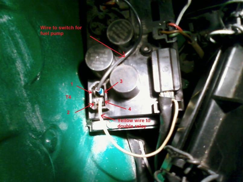 |
   |

 
|
  |
Replies
| ejm |
Aug 2 2008, 04:48 PM
Post
#2
|
|
I can see the light at the end of the tunnel Group: Members Posts: 2,692 Joined: 3-February 03 From: Massachusetts Member No.: 224 Region Association: None |
Which FI system are you installing? They are not wired the same. "Yellow wire" is L-jet which does not use the relays on the board. The pump is powered by the dual relay. Look at the AFC/MPC diagrams here. T4 pinout in the pic below.
Attached image(s) 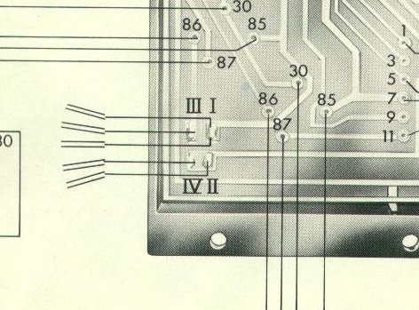
|
|
|
|
| zonedoubt |
Aug 3 2008, 03:02 AM
Post
#3
|
|
Canadian Member Group: Members Posts: 668 Joined: 14-May 03 From: Vancouver, BC Member No.: 696 Region Association: Canada |
QUOTE(ejm @ Aug 2 2008, 03:48 PM)  T4 pinout in the pic below. Thanks, that makes sense. The pump was set up to run whenever the ignition was on. I wired it back up to the harness per the schematic. |
|
|
|
Posts in this topic
 zonedoubt Regulator panel wiring Aug 2 2008, 03:08 PM
 swl Damn - just had a look at the l-jet diagram and it... Aug 3 2008, 07:25 AM swl ah - there it is. Looks like the l-jet doesn... Aug 3 2008, 08:09 AM
 swl should have gone to search rather than haynes :)
... Aug 3 2008, 08:23 AM
swl should have gone to search rather than haynes :)
... Aug 3 2008, 08:23 AM |
1 User(s) are reading this topic (1 Guests and 0 Anonymous Users)
0 Members:

|
Lo-Fi Version | Time is now: 29th May 2024 - 04:55 AM |
Invision Power Board
v9.1.4 © 2024 IPS, Inc.