|
|
|
Porsche, and the Porsche crest are registered trademarks of Dr. Ing. h.c. F. Porsche AG.
This site is not affiliated with Porsche in any way. Its only purpose is to provide an online forum for car enthusiasts. All other trademarks are property of their respective owners. |
|
|


| jimkelly |
 Jul 5 2009, 12:41 PM Jul 5 2009, 12:41 PM
Post
#1
|
|
Delaware USA  Group: Members Posts: 4,969 Joined: 5-August 04 From: Delaware, USA Member No.: 2,460 Region Association: MidAtlantic Region |
i am getting weak voltage on this third pin on my relay board - with key tuned in the on position?? i am trying to trouble shoot why my fuel pump is not getting power. jim
Attached image(s) 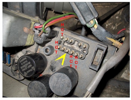
|
   |

 
|
  |
Replies
| jimkelly |
Jul 5 2009, 02:25 PM
Post
#2
|
|
Delaware USA Group: Members Posts: 4,969 Joined: 5-August 04 From: Delaware, USA Member No.: 2,460 Region Association: MidAtlantic Region |
i am pretty sure i read that some people cover the underside with epoxy. i wish all the how to threads were cataloged some how : (
my damn haynes lists the diagram for the relay board as part 3 - but has no breakdown of the pins for part 3 : ( jim Attached image(s) 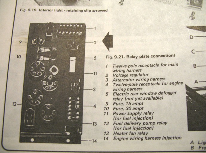
|
|
|
|
| type47 |
Jul 5 2009, 02:37 PM
Post
#3
|
|
Viermeister Group: Members Posts: 4,254 Joined: 7-August 03 From: Vienna, VA Member No.: 994 Region Association: MidAtlantic Region |
QUOTE(jimkelly @ Jul 5 2009, 01:25 PM)  my damn haynes lists the diagram for the relay board as part 3 - but has no breakdown of the pins for part 3 : ( jim you need to look at the relay board diagram on pelican. http://www.pelicanparts.com/914/parts/Elec...lectric_73E.jpg I think that has at least color wiring to all the different pins. A color current path schematic is there also. The Haynes also ID's item #1 as a 12 pin connector when clearly, it's a 14 pin. |
|
|
|
Posts in this topic
 jimkelly weak voltage on 3rd pin ? Jul 5 2009, 12:41 PM
 ghuff I am considering soaking my relay board and fuse p... Jul 5 2009, 01:24 PM
 Dave_Darling I believe that Haynes has diagrams of the relay bo... Jul 5 2009, 09:34 PM 904svo
i am getting weak voltage on this third pin on my... Jul 5 2009, 09:42 PM anderssj Jim,
Here are a couple of relay board "cheat... Jul 6 2009, 09:24 AM jimkelly thanks!
i converted them to jpg in case it he... Jul 6 2009, 11:35 AM
Dave_Darling I believe that Haynes has diagrams of the relay bo... Jul 5 2009, 09:34 PM 904svo
i am getting weak voltage on this third pin on my... Jul 5 2009, 09:42 PM anderssj Jim,
Here are a couple of relay board "cheat... Jul 6 2009, 09:24 AM jimkelly thanks!
i converted them to jpg in case it he... Jul 6 2009, 11:35 AM jimkelly 14 pin Jul 6 2009, 11:37 AM
 |
1 User(s) are reading this topic (1 Guests and 0 Anonymous Users)
0 Members:

|
Lo-Fi Version | Time is now: 24th June 2026 - 06:53 AM |
Invision Power Board
v9.1.4 © 2026 IPS, Inc.