|
|
|
Porsche, and the Porsche crest are registered trademarks of Dr. Ing. h.c. F. Porsche AG.
This site is not affiliated with Porsche in any way. Its only purpose is to provide an online forum for car enthusiasts. All other trademarks are property of their respective owners. |
|
|


| byndbad914 |
 Mar 31 2010, 02:19 PM Mar 31 2010, 02:19 PM
Post
#221
|
|
shoehorn and some butter - it fits  Group: Members Posts: 1,547 Joined: 23-January 06 From: Broomfield, CO Member No.: 5,463 Region Association: None |
Car currently has RSR front struts with custom lower arm setup (sorta like a 935 front end) and the rear is a 5-link setup that is much like any old school 60s-80s open wheel car, GT-40, etc all attached to my tube chassis setup.
Decided I wanted to lower the car more and fix a couple issues with the rear 5-link geom so I started laying out some parts, then decided F it, time for a whole new update (IMG:style_emoticons/default/laugh.gif) I can't leave anything alone. So I measured various available pickup points on the current chassis and whipped up this stuff in Pro/Engineer. The lower A is already a bit different than I have assembled in here, but close enough for convo - and JP was asking to see what I have going - I am sure so he can raz me about whether or not I actually win at DEs (IMG:style_emoticons/default/happy11.gif) I used Pro to lay out the geometry so I could measure camber gain, get zero toe positions for the toe link (which will be adjustable in case I want to put some bumpsteer into the rear), RC height and motion, etc. 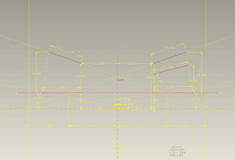 Is this perfectly optimal on all points? Hell no, but much better than what I have and works with existing structure - I am not about to really hack into this car. I can get tabs waterjet cut and welded into place, but not bending/notching tubes in my near future. Besides, it leaves me a little bit of excuse for why I am slow on the track cuz it certainly isn't my driving abilities hahaha (IMG:style_emoticons/default/driving.gif) So here is the rear design - it will be built using the stock trailing arm cut down to not much more than a bearing carrier. yeah, yeah, use this other thing, make that, blah blah - the stock rear bearing assy has worked for a few years now so it is fine. I intend to replace that big bearing every few years regardless of upright used anyways. 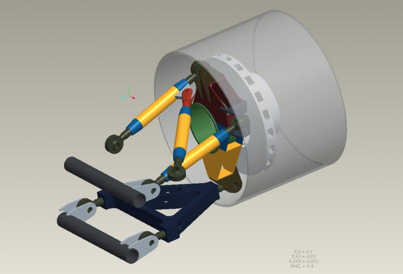 I did the same layout stuff for the front and even am going to be able to use the exact same billet lower A front and rear so that is nice. I can have them waterjetted for about $170 each including the 1.5" plate material, so not bad at all. 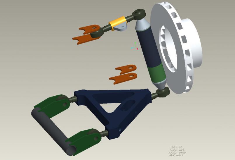 I bought a couple front strut housings from Carquip last week and had my machinist buddy endmill out that monster weld so gonna work on getting them apart down to the stock knuckle, then I have 2" diam chromoly I just got yesterday that I will have him machine down to make the front "upright". Note the two surface colors in the above image - the blue is turned down to fit in the knuckle (50mm) and the green is the stock 2" diam of the tubing - that ridge will be used to exactly place the tube relative to the knuckle so I get both spindles left to right in the exact same spot. The upper forward link will be made on the fly so I didn't bother modeling it. I need to get this stuff in the car with the right pickup points placed, then place some dual adjustable coil over assys which might be tough on the front, then build the forward link around the shock assy. At some point you stop fisting the design and just build it (IMG:style_emoticons/default/shades.gif) Being a structural analyst I also have access to finite element code so I fully analyzed the lower A designs (I have 5 of 'em now hahaha) to make sure they are structurally sufficient. If I get off track in a big way I will likely bend them, but that you can't design for without having a 10lb A arm. These are just over 5 lbs per the modeling software. |
   |

 
|
  |
Replies
| byndbad914 |
May 9 2010, 02:08 PM
Post
#222
|
|
shoehorn and some butter - it fits Group: Members Posts: 1,547 Joined: 23-January 06 From: Broomfield, CO Member No.: 5,463 Region Association: None |
Yeah, I should try to get out there with the camera. Shocks are $825 each with the remote reservoir.
As for that engine, I am a big fan of the LS design - to be honest it is really a small block Ford that has been upgraded. GM guys hate when I say that, but the dimensions of that engine are nearly identical to a mix of the 302/351W/351C Fords, nice center thrust on the mains, heads are similar in layout, and the head gasket is almost identical to a 302/351W with exact same bolt pattern. The early SBC like mine is a bit of a POS as far as design, and when I built mine the LS stuff had just come out so I was wary of it... if I knew then what I know now I would use the LS engine. Actually I would have a stroked 351W Ford had I foreseen going to tube chassis like I did... but that's just me. Only funky thing with them is they seem to push oil thru the PVC system... my neighbor has a new Camaro and he went on a big round about journey down to AZ and back with windy roads, etc. He got back and has 3000 miles on it and it is down a quart on oil! A whole quart in 3K miles on a brand new engine. He said GM claimed they fixed the issue with the LS3 but sounds like they didn't. Key is to just run a catch can inline with the PVC so you don't actually suck the oil into the intake and keep up on topping off the oil. If you programmed around the PVC you could just disconnect it altogether and run a catch-can breather. And you're right, for the money you get a lot with those engines. |
|
|
|
Posts in this topic
 byndbad914 creating new susp for the monster Mar 31 2010, 02:19 PM
 URY914 I see. What about the angle of the dangle? :D Mar 31 2010, 02:24 PM byndbad914 that is something I hold constant - low and to the... Mar 31 2010, 02:25 PM SirAndy Purdy! :wub: Mar 31 2010, 02:43 PM J P Stein It looks like you have set up to get some decent s... Mar 31 2010, 05:24 PM ArtechnikA Tell me about the RSR struts, especially if they... Mar 31 2010, 05:31 PM
 byndbad914 I would really love to move the spring combo inboa... Mar 31 2010, 06:11 PM ArtechnikA
Let's say I'm not interested at Patrick p... Mar 31 2010, 07:40 PM andys Tim,
Nice work. Any issues with roll steer on tha... Apr 1 2010, 01:24 PM stewteral
Tim,
Nice work. Any issues with roll steer on th... Apr 2 2010, 09:50 PM byndbad914 The angle and length I have set up in the design f... Apr 1 2010, 10:50 PM byndbad914 so the whole coil over thing with the RSRs started... Apr 2 2010, 01:31 PM ArtechnikA
So the original RSRs had lower rate springs than ... Apr 2 2010, 01:48 PM byndbad914
no rear adjustable coilovers for 911 AFAIK ;-)
I... Apr 2 2010, 03:41 PM ArtechnikA
no rear adjustable coilovers for 911 AFAIK ;-)
... Apr 2 2010, 04:15 PM jmill Rebel has the RSR strut much cheaper than Patrick. Apr 2 2010, 06:19 PM ArtechnikA
Rebel has the RSR strut much cheaper than Patrick... Apr 2 2010, 06:24 PM sww914
Rebel has the RSR strut much cheaper than Patrick... May 10 2010, 10:54 PM byndbad914 Spring in CO is a bit of a farce really - now is a... Apr 3 2010, 12:48 AM Brett W Have you looked at the 928 front uprights. They a... Apr 6 2010, 08:59 AM byndbad914 looked at 'em - what I couldn't get good c... Apr 6 2010, 01:30 PM ArtechnikA
...the .188" wall 2" diam chromoly tube... Apr 6 2010, 01:41 PM byndbad914 McMaster-Carr was my only source I could find for ... Apr 6 2010, 02:41 PM Brett W Slow your roll there guys. McMaster is steep for ... Apr 6 2010, 03:27 PM byndbad914
Slow your roll there guys. McMaster is steep for... Apr 6 2010, 03:58 PM ArtechnikA
www.speedymetals.com
Here is the tubing you need... Apr 6 2010, 04:07 PM Brett W http://secure.chassisshop.com/partlist/5918/1/
T... Apr 7 2010, 07:50 AM byndbad914
If you are building it out of 4130 you need ER70S... Apr 7 2010, 09:37 PM camaroz1985 Yet another source.
Wicks Aircraft Supply
Used t... Apr 7 2010, 08:55 AM andys Guys,
Aircraft Spruce has .188" wall 2... Apr 7 2010, 10:33 AM byndbad914
Tim, you're not going to like machining the O... Apr 7 2010, 02:51 PM byndbad914 BTW, you guys all suck for telling me this AFTER I... Apr 7 2010, 02:56 PM Brett W Shoulda called first. HEHE Apr 7 2010, 03:40 PM Brett W He your the one driving this thing at a high rate ... Apr 8 2010, 08:44 AM byndbad914 some updates finally - been pushed back a bit as m... Apr 18 2010, 06:41 PM byndbad914 just getting started on the rear stuff too, that w... Apr 18 2010, 06:48 PM andys Hey, some progress.......Looking good!
What a... Apr 19 2010, 10:02 AM J P Stein Were it me, I'd go after that 1 inch scrub....... Apr 19 2010, 10:58 AM byndbad914 I go back and forth on the wheels. I am going to ... Apr 19 2010, 11:16 AM andys If you want to do it on the cheap as a start, you ... Apr 19 2010, 12:02 PM Joe Ricard 2nd the AFCO recommendation. Damn good shock for ... Apr 20 2010, 03:15 PM byndbad914 thanks for the recommendations on shocks - will lo... Apr 20 2010, 09:00 PM camaroz1985 That a-arm looks heavy. Are you machining some of... Apr 21 2010, 09:32 AM andys Tim,
How are the A-arms constructed? Will they be... Apr 21 2010, 09:56 AM byndbad914 A-arms are billet, water jet cut from plate. No m... Apr 21 2010, 11:26 AM stewteral
A-arms are billet, water jet cut from plate. No ... May 10 2010, 11:22 AM byndbad914
I have a question on your billet A-arms: what all... May 10 2010, 02:31 PM Smitty911 I don't know if this helps, but I just found i... Apr 23 2010, 05:14 PM byndbad914 being an engineer I have access to a fair amount o... Apr 23 2010, 09:31 PM Smitty911 I knew you had Pro-E, but I'm not familiar wit... Apr 24 2010, 08:04 AM byndbad914 been a couple weeks with no updates... got the rea... May 8 2010, 10:53 PM Randal
been a couple weeks with no updates... got the re... May 9 2010, 09:05 AM Randal Also being an egineer, as well as an engine builde... May 9 2010, 10:33 AM Randal
Yeah, I should try to get out there with the came... May 9 2010, 03:52 PM byndbad914
How do you think the Penske shocks will compare t... May 9 2010, 05:22 PM andys Probably don't need to go the E-Rod motor sinc... May 9 2010, 04:21 PM byndbad914 couple shots of the rear, everything is laid out w... May 9 2010, 06:09 PM byndbad914 deet deet deet deet deet deet deet duhdee... May 10 2010, 10:58 PM byndbad914 upright pieces all cut from box beam - I will use ... May 10 2010, 10:59 PM byndbad914 mo'
May 10 2010, 11:01 PM byndbad914 mo'
May 10 2010, 11:01 PM byndbad914 mo'
May 10 2010, 11:02 PM byndbad914 my friend back years ago - Chuck McKinney - lived ... May 10 2010, 11:13 PM effutuo101 Love this! May 11 2010, 12:21 PM byndbad914
Love this!
Thanks!
Just got off the phon... May 11 2010, 02:00 PM brilliantrot Those rates sound about right. Not to long ago I w... May 11 2010, 03:30 PM Brett W Damn its a shame I couldn't get by there this ... May 13 2010, 10:40 AM byndbad914 I talked to Xtrac a few years back at the PRI show... May 13 2010, 01:07 PM Brett W Damn Toyota 4wd clutch job. I will hit you up whe... May 14 2010, 08:41 AM byndbad914 hopefully it is back together by then <_<
... May 15 2010, 01:20 AM andys Tim,
You forgettin your roots? Hell you could get... May 15 2010, 05:31 PM byndbad914 yeah, I just don't like how they look. I plan... May 15 2010, 11:28 PM byndbad914 more fun in the saga today - found that the rear w... May 16 2010, 10:22 PM Brett W We just went through issues with Diamond wheels. ... May 17 2010, 02:24 PM byndbad914 pisser is I started out to get CCW wheels and foun... May 17 2010, 05:54 PM Brett W I agree. Possibly sell them to someone who can us... May 18 2010, 10:32 AM andys Guess I'm always looking at things from a raci... May 18 2010, 10:35 AM byndbad914 CCW has an offset that I would prefer too... argh.... May 18 2010, 02:33 PM andys Bet it felt good to find those dicrepancies; not g... May 18 2010, 03:21 PM byndbad914
Bet it felt good to find those dicrepancies; not ... May 18 2010, 04:49 PM byndbad914 been pretty busy on the car actually - got the rea... May 24 2010, 05:38 PM byndbad914 RE: creating new susp for the monster May 24 2010, 05:39 PM byndbad914 RE: creating new susp for the monster May 24 2010, 05:40 PM byndbad914 having the front upright tubes redone (my bad, sli... May 24 2010, 05:46 PM Brett W Dude, what does your rear bump toe curve look like... May 27 2010, 02:48 PM byndbad914 Did everything in the computer to make sure that a... May 27 2010, 06:58 PM andys After all the fabrication is done, the real work s... May 28 2010, 09:34 AM byndbad914 doing adjustments to the five link setup before wa... May 28 2010, 08:19 PM byndbad914 relocated the front brackets a bit to lower the fr... May 29 2010, 07:24 PM byndbad914 RE: creating new susp for the monster May 29 2010, 07:24 PM byndbad914 Penske shocks
May 29 2010, 07:25 PM byndbad914 Brett - this might help to see the arms in relatio... May 29 2010, 07:27 PM stewteral
Brett - this might help to see the arms in relati... May 31 2010, 11:02 PM byndbad914 thanks to all for the kind remarks!
Brett- ye... Jun 1 2010, 01:22 PM Randal
thanks to all for the kind remarks!
Brett- y... Jun 2 2010, 09:04 AM byndbad914 a look-see at the front uprights, no upper A arms ... May 29 2010, 07:31 PM puff adder Amazing! Just awesome. As an artist and creat... May 31 2010, 05:50 PM Brett W That looks better. Must have been perspective. Y... Jun 1 2010, 12:40 PM Brett W A little toe in under braking isn't a bad thi... Jun 2 2010, 08:45 AM
byndbad914 I would really love to move the spring combo inboa... Mar 31 2010, 06:11 PM ArtechnikA
Let's say I'm not interested at Patrick p... Mar 31 2010, 07:40 PM andys Tim,
Nice work. Any issues with roll steer on tha... Apr 1 2010, 01:24 PM stewteral
Tim,
Nice work. Any issues with roll steer on th... Apr 2 2010, 09:50 PM byndbad914 The angle and length I have set up in the design f... Apr 1 2010, 10:50 PM byndbad914 so the whole coil over thing with the RSRs started... Apr 2 2010, 01:31 PM ArtechnikA
So the original RSRs had lower rate springs than ... Apr 2 2010, 01:48 PM byndbad914
no rear adjustable coilovers for 911 AFAIK ;-)
I... Apr 2 2010, 03:41 PM ArtechnikA
no rear adjustable coilovers for 911 AFAIK ;-)
... Apr 2 2010, 04:15 PM jmill Rebel has the RSR strut much cheaper than Patrick. Apr 2 2010, 06:19 PM ArtechnikA
Rebel has the RSR strut much cheaper than Patrick... Apr 2 2010, 06:24 PM sww914
Rebel has the RSR strut much cheaper than Patrick... May 10 2010, 10:54 PM byndbad914 Spring in CO is a bit of a farce really - now is a... Apr 3 2010, 12:48 AM Brett W Have you looked at the 928 front uprights. They a... Apr 6 2010, 08:59 AM byndbad914 looked at 'em - what I couldn't get good c... Apr 6 2010, 01:30 PM ArtechnikA
...the .188" wall 2" diam chromoly tube... Apr 6 2010, 01:41 PM byndbad914 McMaster-Carr was my only source I could find for ... Apr 6 2010, 02:41 PM Brett W Slow your roll there guys. McMaster is steep for ... Apr 6 2010, 03:27 PM byndbad914
Slow your roll there guys. McMaster is steep for... Apr 6 2010, 03:58 PM ArtechnikA
www.speedymetals.com
Here is the tubing you need... Apr 6 2010, 04:07 PM Brett W http://secure.chassisshop.com/partlist/5918/1/
T... Apr 7 2010, 07:50 AM byndbad914
If you are building it out of 4130 you need ER70S... Apr 7 2010, 09:37 PM camaroz1985 Yet another source.
Wicks Aircraft Supply
Used t... Apr 7 2010, 08:55 AM andys Guys,
Aircraft Spruce has .188" wall 2... Apr 7 2010, 10:33 AM byndbad914
Tim, you're not going to like machining the O... Apr 7 2010, 02:51 PM byndbad914 BTW, you guys all suck for telling me this AFTER I... Apr 7 2010, 02:56 PM Brett W Shoulda called first. HEHE Apr 7 2010, 03:40 PM Brett W He your the one driving this thing at a high rate ... Apr 8 2010, 08:44 AM byndbad914 some updates finally - been pushed back a bit as m... Apr 18 2010, 06:41 PM byndbad914 just getting started on the rear stuff too, that w... Apr 18 2010, 06:48 PM andys Hey, some progress.......Looking good!
What a... Apr 19 2010, 10:02 AM J P Stein Were it me, I'd go after that 1 inch scrub....... Apr 19 2010, 10:58 AM byndbad914 I go back and forth on the wheels. I am going to ... Apr 19 2010, 11:16 AM andys If you want to do it on the cheap as a start, you ... Apr 19 2010, 12:02 PM Joe Ricard 2nd the AFCO recommendation. Damn good shock for ... Apr 20 2010, 03:15 PM byndbad914 thanks for the recommendations on shocks - will lo... Apr 20 2010, 09:00 PM camaroz1985 That a-arm looks heavy. Are you machining some of... Apr 21 2010, 09:32 AM andys Tim,
How are the A-arms constructed? Will they be... Apr 21 2010, 09:56 AM byndbad914 A-arms are billet, water jet cut from plate. No m... Apr 21 2010, 11:26 AM stewteral
A-arms are billet, water jet cut from plate. No ... May 10 2010, 11:22 AM byndbad914
I have a question on your billet A-arms: what all... May 10 2010, 02:31 PM Smitty911 I don't know if this helps, but I just found i... Apr 23 2010, 05:14 PM byndbad914 being an engineer I have access to a fair amount o... Apr 23 2010, 09:31 PM Smitty911 I knew you had Pro-E, but I'm not familiar wit... Apr 24 2010, 08:04 AM byndbad914 been a couple weeks with no updates... got the rea... May 8 2010, 10:53 PM Randal
been a couple weeks with no updates... got the re... May 9 2010, 09:05 AM Randal Also being an egineer, as well as an engine builde... May 9 2010, 10:33 AM Randal
Yeah, I should try to get out there with the came... May 9 2010, 03:52 PM byndbad914
How do you think the Penske shocks will compare t... May 9 2010, 05:22 PM andys Probably don't need to go the E-Rod motor sinc... May 9 2010, 04:21 PM byndbad914 couple shots of the rear, everything is laid out w... May 9 2010, 06:09 PM byndbad914 deet deet deet deet deet deet deet duhdee... May 10 2010, 10:58 PM byndbad914 upright pieces all cut from box beam - I will use ... May 10 2010, 10:59 PM byndbad914 mo'
May 10 2010, 11:01 PM byndbad914 mo'
May 10 2010, 11:01 PM byndbad914 mo'
May 10 2010, 11:02 PM byndbad914 my friend back years ago - Chuck McKinney - lived ... May 10 2010, 11:13 PM effutuo101 Love this! May 11 2010, 12:21 PM byndbad914
Love this!
Thanks!
Just got off the phon... May 11 2010, 02:00 PM brilliantrot Those rates sound about right. Not to long ago I w... May 11 2010, 03:30 PM Brett W Damn its a shame I couldn't get by there this ... May 13 2010, 10:40 AM byndbad914 I talked to Xtrac a few years back at the PRI show... May 13 2010, 01:07 PM Brett W Damn Toyota 4wd clutch job. I will hit you up whe... May 14 2010, 08:41 AM byndbad914 hopefully it is back together by then <_<
... May 15 2010, 01:20 AM andys Tim,
You forgettin your roots? Hell you could get... May 15 2010, 05:31 PM byndbad914 yeah, I just don't like how they look. I plan... May 15 2010, 11:28 PM byndbad914 more fun in the saga today - found that the rear w... May 16 2010, 10:22 PM Brett W We just went through issues with Diamond wheels. ... May 17 2010, 02:24 PM byndbad914 pisser is I started out to get CCW wheels and foun... May 17 2010, 05:54 PM Brett W I agree. Possibly sell them to someone who can us... May 18 2010, 10:32 AM andys Guess I'm always looking at things from a raci... May 18 2010, 10:35 AM byndbad914 CCW has an offset that I would prefer too... argh.... May 18 2010, 02:33 PM andys Bet it felt good to find those dicrepancies; not g... May 18 2010, 03:21 PM byndbad914
Bet it felt good to find those dicrepancies; not ... May 18 2010, 04:49 PM byndbad914 been pretty busy on the car actually - got the rea... May 24 2010, 05:38 PM byndbad914 RE: creating new susp for the monster May 24 2010, 05:39 PM byndbad914 RE: creating new susp for the monster May 24 2010, 05:40 PM byndbad914 having the front upright tubes redone (my bad, sli... May 24 2010, 05:46 PM Brett W Dude, what does your rear bump toe curve look like... May 27 2010, 02:48 PM byndbad914 Did everything in the computer to make sure that a... May 27 2010, 06:58 PM andys After all the fabrication is done, the real work s... May 28 2010, 09:34 AM byndbad914 doing adjustments to the five link setup before wa... May 28 2010, 08:19 PM byndbad914 relocated the front brackets a bit to lower the fr... May 29 2010, 07:24 PM byndbad914 RE: creating new susp for the monster May 29 2010, 07:24 PM byndbad914 Penske shocks
May 29 2010, 07:25 PM byndbad914 Brett - this might help to see the arms in relatio... May 29 2010, 07:27 PM stewteral
Brett - this might help to see the arms in relati... May 31 2010, 11:02 PM byndbad914 thanks to all for the kind remarks!
Brett- ye... Jun 1 2010, 01:22 PM Randal
thanks to all for the kind remarks!
Brett- y... Jun 2 2010, 09:04 AM byndbad914 a look-see at the front uprights, no upper A arms ... May 29 2010, 07:31 PM puff adder Amazing! Just awesome. As an artist and creat... May 31 2010, 05:50 PM Brett W That looks better. Must have been perspective. Y... Jun 1 2010, 12:40 PM Brett W A little toe in under braking isn't a bad thi... Jun 2 2010, 08:45 AM |
2 User(s) are reading this topic (2 Guests and 0 Anonymous Users)
0 Members:

|
Lo-Fi Version | Time is now: 2nd June 2024 - 08:45 AM |
Invision Power Board
v9.1.4 © 2024 IPS, Inc.