|
|
|
Porsche, and the Porsche crest are registered trademarks of Dr. Ing. h.c. F. Porsche AG.
This site is not affiliated with Porsche in any way. Its only purpose is to provide an online forum for car enthusiasts. All other trademarks are property of their respective owners. |
|
|


| enikolayev |
 Jun 28 2010, 10:23 PM Jun 28 2010, 10:23 PM
Post
#1
|
|
Member  Group: Members Posts: 50 Joined: 18-November 07 From: Gulfport, MS Member No.: 8,349 Region Association: South East States |
It has been three years since the car drove but i have finally rebuilt the engine and reinstalled it. Now i'm trying to wire it all up. Too bad i didn't keep a record of where everything went.
I'm looking at the relay board diagram and most of the wires are accounted for except a few oddballs don't seem to match. The car is a '74 with a 1.8 on Webbers Wires in italics are not accounted for 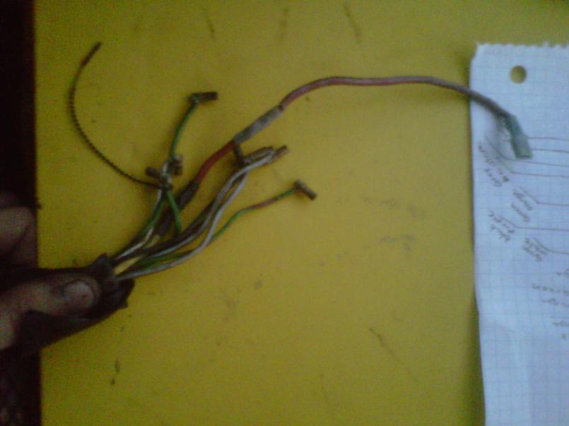 I think these wires go to the area outlined in red on the Relay Board Diagram (to be posted) Here we have the following wires: Green w/ Red Stripe Green w/ Black stripe Green (2) Grey w/ Brown Stripe Black w/ Red Stripe Black w/ Purple Stripe White Thick Yellow which turns into Red |
   |

 
|
  |
Replies
| Spoke |
Jun 29 2010, 05:18 AM
Post
#2
|
|
Jerry Group: Members Posts: 6,992 Joined: 29-October 04 From: Allentown, PA Member No.: 3,031 Region Association: None |
You are correct that the wires from Post 1 go to the red connector and those from Post 2 go to the green connector. As mentioned, you should really try to procure the plastic connectors that these wires go to. Put a WTB: ad in the classifieds for the 2 connectors.
Use your voltmeter to check all wires to make sure you get the right ones. Don't go by what I tell you. Check these wires yourself to be sure. Show some pics where the other ends of the wires in question go and we should be able to help figure this out. From Post 1: Thick yellow which turns to red: I don't know what this means that yellow turns to red, but the thick yellow wire from this connector could be to pin 6 which goes to the starter. Here are the wire colors and connections from my 74 schematic from my Haynes manual: Pin 1 GR/RD Oil Pressure Pin 2 GY/BR Backup Light Pin 4 GY/BR Backup Light Pin 5 BK/PU Tach Pin 6 YW Starter Pin 7 BK 12V to Coil Pin 10 GREEN Heater Blower Pin 11 GREEN Heater Blower Pin 12 BK/RD Supplementary Air Valve From Post 2: Here's what my schematic says: Pin 1 YW Starter Pin 2 BL Alternator Light Pin 3 GY/BR Backup Light Pin 4 GY/BR Backup Light Pin 5 GR/RD Oil Pressure Pin 7 BK/PU Tach Pin 8 BK 12V to Coil Pin 9 GR/WH Heater Blower Switch Pin 10 BR Ground Pin 11 GR Heater Blower Pin 12 RD Battery Pin 13 BK/RD Fuel Pump Pin 14 RD Battery |
|
|
|
Posts in this topic
 enikolayev Relay board wiring help Jun 28 2010, 10:23 PM
 enikolayev
I think this group goes into the area outlined i... Jun 28 2010, 10:32 PM enikolayev
And finally the Relay Board Diagram
Thanks in a... Jun 28 2010, 10:34 PM type47 The connection you circled in green is the "1... Jun 29 2010, 02:21 AM enikolayev My relay board had no connector. The wires go dire... Jun 29 2010, 02:24 AM type47 Maybe the connectors were "lost" during ... Jun 29 2010, 02:28 AM 9146986 You need to source a salvaged 12 pin female connec... Jun 29 2010, 06:14 AM detoxcowboy http://bowlsby.net/914/WiringHarnesses/
at the ne... Jun 29 2010, 08:26 AM type47 These are pix of the 14 pin connector. I can't... Jun 29 2010, 09:27 AM enikolayev Alright i've got all of the schematics from pe... Jun 29 2010, 01:52 PM Jeff Bowlsby I have an extra 14-pin connector housing (no conta... Jun 29 2010, 01:56 PM Spoke I've got an extra 12 pin connector if you need... Jun 29 2010, 07:47 PM enikolayev The WTB thread proved fruitful. I've got the p... Jun 30 2010, 09:45 PM enikolayev
While i wait for the parts, could you guys help... Jul 1 2010, 03:44 PM
enikolayev
I think this group goes into the area outlined i... Jun 28 2010, 10:32 PM enikolayev
And finally the Relay Board Diagram
Thanks in a... Jun 28 2010, 10:34 PM type47 The connection you circled in green is the "1... Jun 29 2010, 02:21 AM enikolayev My relay board had no connector. The wires go dire... Jun 29 2010, 02:24 AM type47 Maybe the connectors were "lost" during ... Jun 29 2010, 02:28 AM 9146986 You need to source a salvaged 12 pin female connec... Jun 29 2010, 06:14 AM detoxcowboy http://bowlsby.net/914/WiringHarnesses/
at the ne... Jun 29 2010, 08:26 AM type47 These are pix of the 14 pin connector. I can't... Jun 29 2010, 09:27 AM enikolayev Alright i've got all of the schematics from pe... Jun 29 2010, 01:52 PM Jeff Bowlsby I have an extra 14-pin connector housing (no conta... Jun 29 2010, 01:56 PM Spoke I've got an extra 12 pin connector if you need... Jun 29 2010, 07:47 PM enikolayev The WTB thread proved fruitful. I've got the p... Jun 30 2010, 09:45 PM enikolayev
While i wait for the parts, could you guys help... Jul 1 2010, 03:44 PM
 Cap'n Krusty
While i wait for the parts, could you guys hel... Jul 1 2010, 04:18 PM type47 My first guess was for the double relay since you ... Jul 1 2010, 03:51 PM windforfun Do you have wiring diagrams for the car? They are... Jul 1 2010, 03:57 PM
Cap'n Krusty
While i wait for the parts, could you guys hel... Jul 1 2010, 04:18 PM type47 My first guess was for the double relay since you ... Jul 1 2010, 03:51 PM windforfun Do you have wiring diagrams for the car? They are... Jul 1 2010, 03:57 PM |
1 User(s) are reading this topic (1 Guests and 0 Anonymous Users)
0 Members:

|
Lo-Fi Version | Time is now: 10th June 2024 - 12:06 AM |
Invision Power Board
v9.1.4 © 2024 IPS, Inc.