|
|
|
Porsche, and the Porsche crest are registered trademarks of Dr. Ing. h.c. F. Porsche AG.
This site is not affiliated with Porsche in any way. Its only purpose is to provide an online forum for car enthusiasts. All other trademarks are property of their respective owners. |
|
|


| Spoke |
 Apr 26 2018, 10:47 PM Apr 26 2018, 10:47 PM
Post
#1
|
|
Jerry  Group: Members Posts: 6,986 Joined: 29-October 04 From: Allentown, PA Member No.: 3,031 Region Association: None |
A Porsche 356 owner contacted me about converting a set of Marchal fog running lights to LEDs. We talked about it and he asked if I could do it in 6 weeks. My response was I've never done a high power LED headlamp so it's more of a project than a product. The Marchal running light is shown on this file-folder picture of a 356. That's not me nor the owner. (IMG:style_emoticons/default/smile.gif) 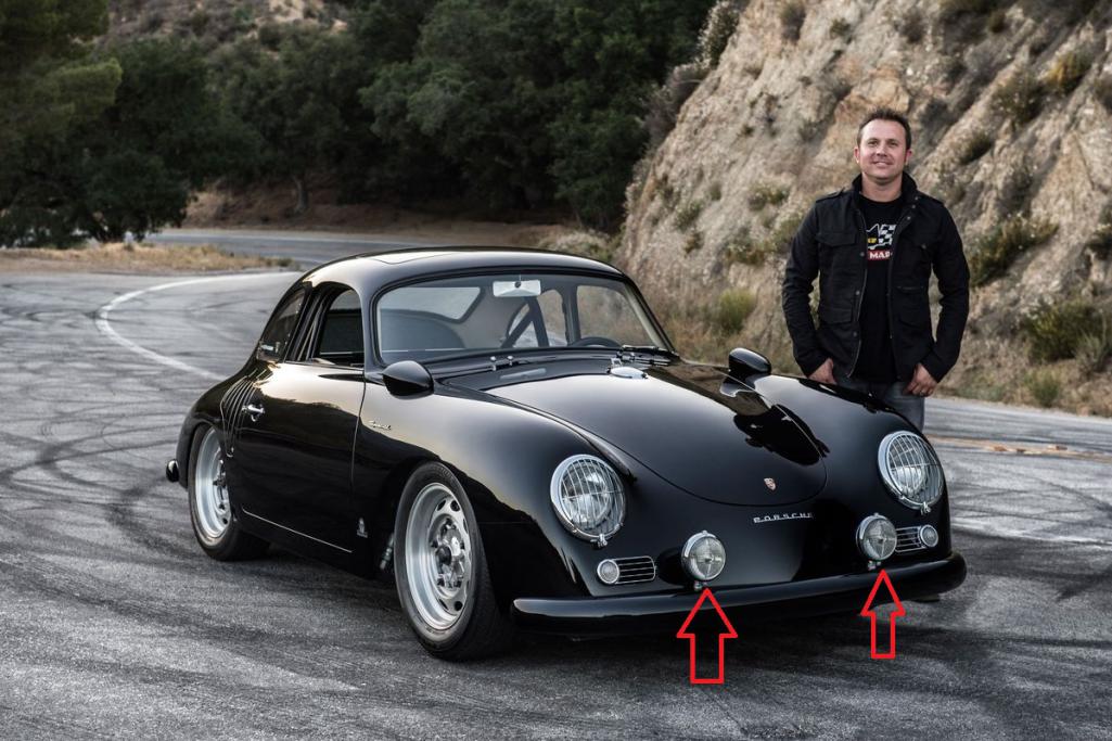 The idea was to design an LED-only board attached to a large heat sink and use a step-up dc-dc converter on a separate board to provide 0.275Amp to the LEDs. The LEDs are Cree XP-G3 surface mount LEDs. These have a maximum current of 2 amps. The LEDs require a lens to focus the light pattern. The XP-G3 have a wide output light pattern and can't be used 'naked'. The lens per LED are Carclo's 10049 lens with a light pattern shown below. 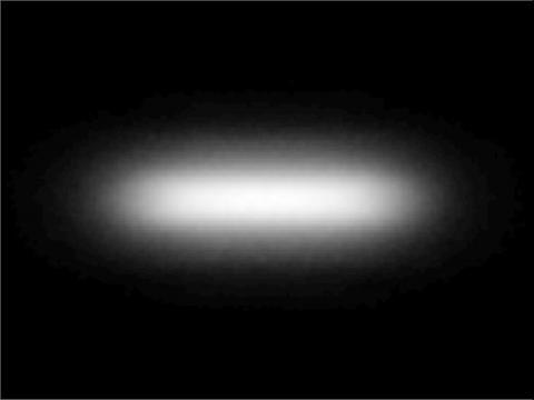 The LED board uses 19 LEDs with lenses and holders. The board will be backed by a very large heat sink. The main killer of LEDs is heat. 2 amps through an LED with 3.5V is 7W in less than 1/4" square area. Massive power dissipation/heat in a very small area. The PCB really should be an aluminum PCB but they are really expensive so the PCB is FR4 and is thin at 0.8mm to minimize thermal impedance of FR4. Vias from top to bottom are liberally applied to provide as much metal top-to-bottom for heat transfer. The clear area of the bottom of the board will allow maximum heat flow to the heat sink. 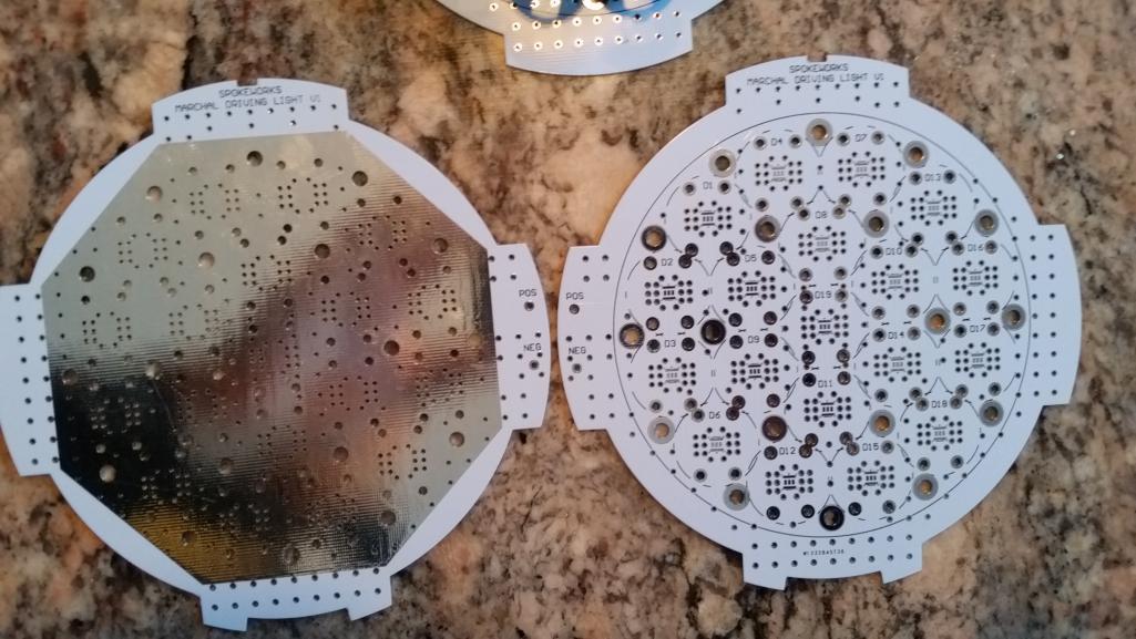 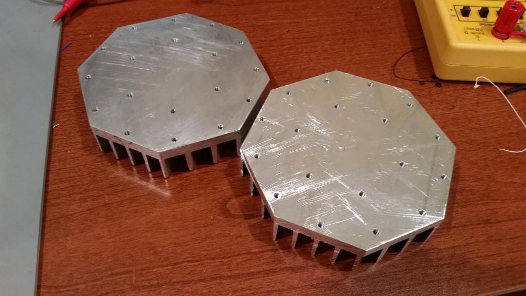 |
   |

 
|
  |
Replies
| Spoke |
May 2 2018, 10:43 AM
Post
#2
|
|
Jerry Group: Members Posts: 6,986 Joined: 29-October 04 From: Allentown, PA Member No.: 3,031 Region Association: None |
The converter board was redesigned with a much larger MOSFET in a D2PAK package with 0.0056 ohm ON resistance and a small heatsink for the MOSFET. The original MOSFET was in a DPAK case and had 0.35 ohm ON resistance. Quite a lot less resistance considering the MOSFET is switching almost 2 amps.
Also went with a larger inductor with a much lower series resistance. Since the converter board will be mounted on the back of the LED heatsink, I tried to shield the converter board from the heatsink with a blank FR4 board. With the fixture completely assembled, the case of the MOSFET still gets above 110C and the ambient air temperature inside the fixture is getting to about 80C. Pretty hot but should still be ok. This is with no air movement. (ie., the car is stationary with ambient 23C). With airflow provided, the temps drop as much as 20C. Attached thumbnail(s) 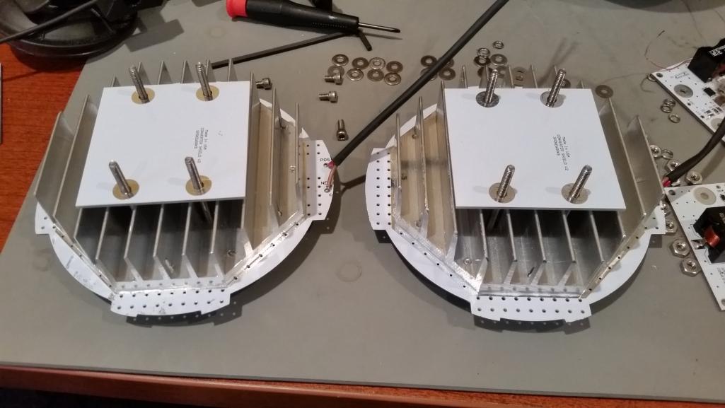 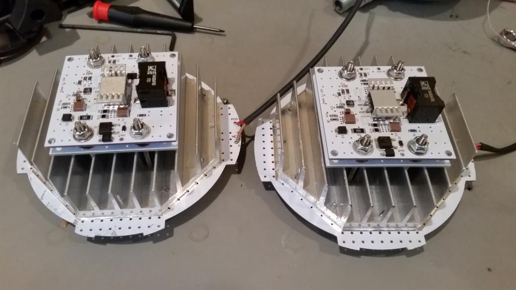 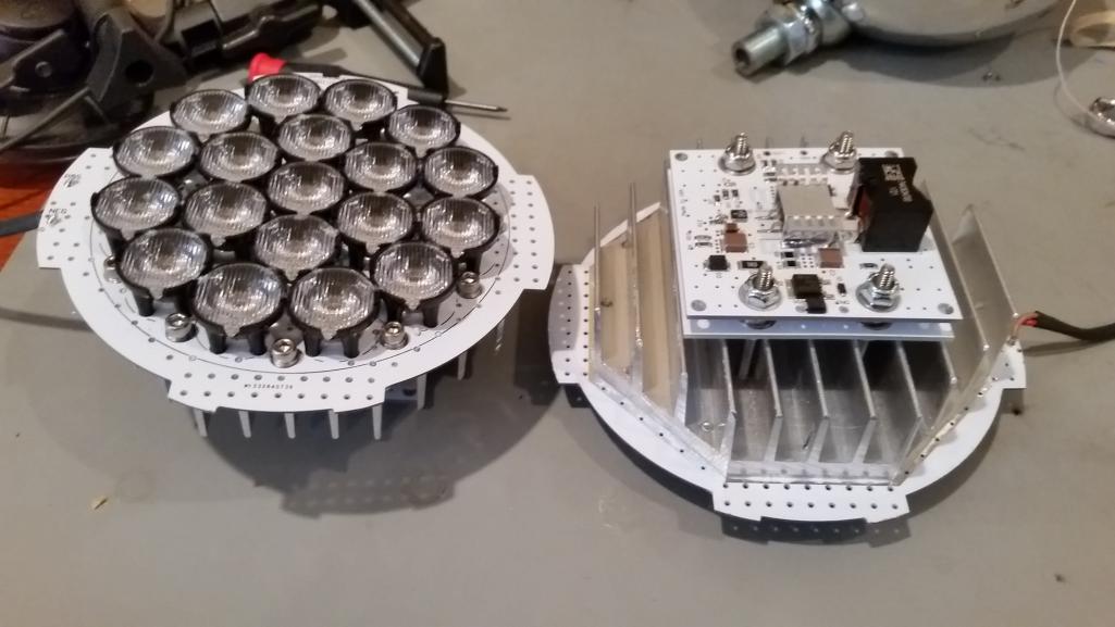 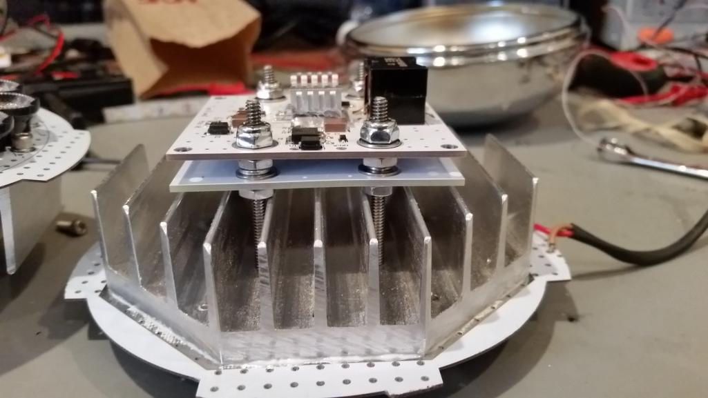
|
|
|
|
Posts in this topic
 Spoke OT: Marchal LED Conversion for 356 Apr 26 2018, 10:47 PM
 Spoke Here's a picture of the XP-G3 LEDs as they wer... Apr 26 2018, 11:44 PM Edward Blume Looks good. :headbanger: Apr 27 2018, 04:18 AM mepstein Love the black 356!
I put Spoke's lights o... Apr 27 2018, 04:52 AM JmuRiz Cool project! Apr 27 2018, 07:03 AM Coondog Great job. I have said it a thousand times.
You... Apr 27 2018, 07:15 AM Spoke This was the first light-up of the full 19 LED lam... Apr 27 2018, 07:59 AM
Spoke Here's a picture of the XP-G3 LEDs as they wer... Apr 26 2018, 11:44 PM Edward Blume Looks good. :headbanger: Apr 27 2018, 04:18 AM mepstein Love the black 356!
I put Spoke's lights o... Apr 27 2018, 04:52 AM JmuRiz Cool project! Apr 27 2018, 07:03 AM Coondog Great job. I have said it a thousand times.
You... Apr 27 2018, 07:15 AM Spoke This was the first light-up of the full 19 LED lam... Apr 27 2018, 07:59 AM
 Chris914n6
This is the light pattern on the ceiling 6 feet f... Apr 28 2018, 01:33 PM Spoke This is the first converter board driving the LED ... Apr 27 2018, 09:15 PM Mueller Pretty damn slick and you've inspired me to do... May 2 2018, 10:54 AM
Chris914n6
This is the light pattern on the ceiling 6 feet f... Apr 28 2018, 01:33 PM Spoke This is the first converter board driving the LED ... Apr 27 2018, 09:15 PM Mueller Pretty damn slick and you've inspired me to do... May 2 2018, 10:54 AM |
1 User(s) are reading this topic (1 Guests and 0 Anonymous Users)
0 Members:

|
Lo-Fi Version | Time is now: 28th May 2024 - 05:20 PM |
Invision Power Board
v9.1.4 © 2024 IPS, Inc.