|
|
|
Porsche, and the Porsche crest are registered trademarks of Dr. Ing. h.c. F. Porsche AG.
This site is not affiliated with Porsche in any way. Its only purpose is to provide an online forum for car enthusiasts. All other trademarks are property of their respective owners. |
|
|


| Not_A_Six |
 Aug 15 2020, 10:22 AM Aug 15 2020, 10:22 AM
Post
#1
|
|
Member  Group: Members Posts: 110 Joined: 28-November 18 From: North Idaho Member No.: 22,682 Region Association: Pacific Northwest |
EDIT: See post #17 for an update that contradicts some of the findings in this OP. See also post #29 for the final results.
I've recently gone down the rabbit hole of D-Jet and MPS tuning and wanted to post what I've learned in the hopes that it may help others. I also hope to start a discussion with some of the experts here in case I've missed something, or there are errors in my analysis. Background: With the increased displacement (2056cc) and non-stock cam (Webcam 73) in my engine, I was experiencing Air-Fuel Mixture (AFR) issues across the range of temperature, load, and rpm conditions. This post concerns MPS tuning. At the moment, I'm also working on modifying component values inside the ECU to change the Volumetric Efficiency curve to better match the non-stock AFR vs RPM characteristics of my engine. If there is any interest in poking around that deep in the bowels of D-Jet, I'll start a thread when I finish. (IMG:style_emoticons/default/blink.gif) Engine Configuration: '73 2.0 Displacement: 2056cc Cam: Webcam 73 ECU: Porsche nnn906021E (Bosch 280000037) MPS: Porsche 022906051E (Bosch 0280100049) w/ Tangerine Racing tuning kit + spacer ring; tuned to emulate 0280100037 CHT: 0280130017 w/ 270-ohm ballast resistor and steel spacer Vacuum Hoses routed per @JeffBowlsby (see link below) Fuel Pressure: 35 psi (at the moment -- still tuning) PCV: Modern PCV valve routed to plenum Ignition: 123Ignition PORSCHE-4-R-V-IE, running profile "1" w/ Vac Advance Timing: 27 degrees at 3500 rpm (w/o vacuum adv/ret) Equipment used: Generic handheld vacuum pump/gauge misc hoses+fittings AMPROBE LCR55A meter (on 20H scale) Innovate Motorsports (3837) LM-2 (BASIC) Digital Air/Fuel Ratio Wideband Meter w/ Bosch LSU 4.9 Home-fabricated tailpipe "Stinger" w/ O2 Sensor Bung TIG welded on Reference Info: Vacuum Hose Routing MPS Theory of Operation @pbanders AFR vs Manifold Vacuum Issue @Demick Analysis: 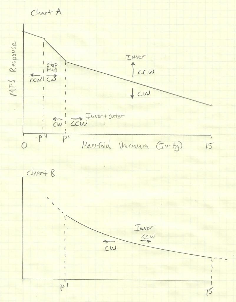 As you can see in the "Chart A" sketch above, the MPS Inner Screw (in isolation), Outer Screw+Inner Screw (together), and Stop Plug Screw can be used to tune the MPS's affect on the AFR (via its effect on the Fuel Injection pulse width) vs Manifold Vacuum. As shown, the Inner Screw affects the mixture over the whole vacuum range; the Inner+Outer Screw controls the onset pressure P' where the diaphragm begins to lift off the part-load stop; the Stop Plug Screw controls the final pressure P'' where the diaphragm comes to rest on the full-load stop. On this chart, "up" corresponds to a longer FI pulse; "down" to a shorter FI pulse. For details, see pbanders's excellent link, above. I had previously thought that the effect of the Inner Screw was similar to that of changing the fuel pressure via the fuel pressure regulator. Namely: Inner Screw CCW = Increase Fuel Pressure => Richer AFR across entire vacuum range Inner Screw CW = Decrease Fuel Pressure => Leaner AFR across entire vacuum range There appeared to be no way to change the slope of the MPS Response curve in the region from 15 In-Hg to P'. And, I was experiencing the same problem that Demick posted about years ago in the thread linked above. Namely, the AFR would become too lean under moderate-load conditions across all RPM's, like this (from Demick's post): (IMG:http://www.914world.com/bbs2/uploads/post-2-1096387565.jpg) To fix the lean condition around 6-8 In-Hg, it's really necessary to change the slope of the MPS response curve, not just raise or lower the whole curve. However, there appears to be hope. It seems that the MPS inductance is not simply linear WRT manifold pressure in the 15 In-Hg to P' region. I speculate that this may be due to non-linearity in the MPS Inductance across its range of movement and/or the effect of the MPS spring. The result is that the curve seems to look more like the "Chart B" sketch above. And, the effect of turning the MPS inner screw isn't really raising or lower the entire curve, but rather shifting the Chart B curve left/right. (Chart B is a really rough sketch, and may even have the convexity backwards. For a more quantitative look, see below.) I measured the inductance of my MPS at two different inner-screw settings: The red curve is the MPS tuned to pbanders's values corrected for 700 Torr ambient pressure. The blue curve represents an attempt to richen the AFR by turning the inner screw CCW. 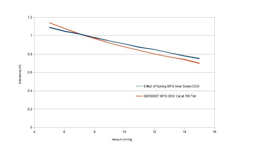 As you can see, the slope of the red curve is steeper than the blue curve in this region. Apparently, turning the inner screw CCW has the effect of reducing the slope by raising the right end, rather than raising the whole curve. I'm surprised that the curves cross around 7 In-Hg and that the blue curve value is less than the red curve value at the left side of the chart. This may be due to the effect of the part-load stop coming into play near P', measurement error, or something else. (IMG:style_emoticons/default/confused24.gif) The salient point, however, is that adjusting the inner screw affects the slope of the curve, whereas presumably adjusting the fuel pressure does not. The opens the possibility of tuning the AFR vs Manifold pressure curve by trading off fuel pressure vs inner screw position: Increase Fuel Pressure + Turn Inner Screw CW => Enrich 6-8 In-Hg region Decrease Fuel Pressure + Turn Inner Screw CCW = Lean out 6-8 In-Hg region I experienced the same problem that Demick did (too lean at 6-8 In-Hg across all RPM), and have largely solved the problem by adjusting the fuel pressure up (to 35 psi currently), then tuning the MPS to set the AFR across the entire range of manifold vacuum levels. I hope this is helpful to somebody. Comments are welcome. If I've made any errors, please feel free to beat me over the head. (IMG:style_emoticons/default/splat.gif) Cheers. (IMG:style_emoticons/default/beerchug.gif) |
   |

 
|
  |
Replies
| BeatNavy |
Aug 16 2020, 06:19 AM
Post
#2
|
|
Certified Professional Scapegoat Group: Members Posts: 2,954 Joined: 26-February 14 From: Easton, MD Member No.: 17,042 Region Association: MidAtlantic Region |
Just for fun I'll throw in some of my data and "analysis" from a few years ago. This was when I was trying to tune a 2056 with a stock cam and later a 2056 with a Raby 9950 (or 9550, whichever it is). I think the latter is similar to a Webcam 73, or maybe even the same grind.
I ended up comparing the following for vacuum / inductance numbers for the 043 MPS, which should have been correct for my '74 D-Jet setup (and compatible with the 043 ECU): 1. Anders' numbers for MPS tuning on his website. 2. An 043 "Primary" that I rebuilt using Chris Foley's kit. This was the one I fiddled with the most in terms of tuning and driving. 3. 043 "Spare." This one was also rebuilt, and I used this kind of as my fallback if I screwed up the primary too badly. I also used it to compare how the car ran with the other one. 4. 043 "Reman." This one was rebuilt and tuned years ago by that company that used to perform this service years ago ("Fuel Injection Company" or whatever it is/was). I did not mess with this one. 5. 043 "Stock." Thanks to the yard sale at Jim McLeod's (RIP (IMG:style_emoticons/default/sad.gif) ) a couple of years ago I managed to acquire a working, unmolested 043. Used this primarily to baseline my inductance meter's numbers against those of Anders. Here are the results in table form. Remember, I was primarily tuning 043 "Primary" and "Spare," so those numbers could be all over the place. I've got the slope in there, but the most relevant slope is that over the "linear region" which I think Anders defines as between 6 and 18 in Hg. 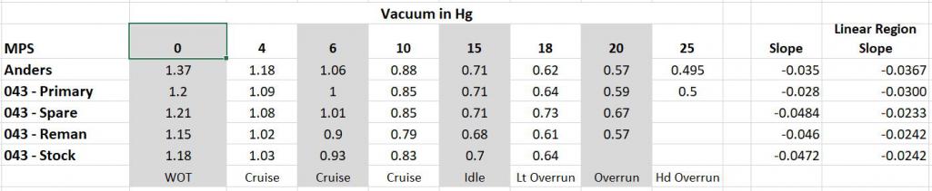 And here's the graph, such as it is. 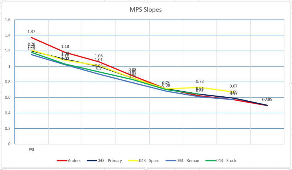 Here are my lessons learned: 1. I spend a LOT of time on this, and I learned a lot, which was enjoyable. But I got more return out of that than any performance increase or optimization (IMG:style_emoticons/default/smile.gif) 2. Inductance meters seem to vary significantly. I'm not sure why this is (I know mine was a cheap one, not a Wavetek), but I know others have had similar findings. You can see that my stock 043 didn't even get close to Anders' numbers, which I found interesting. It also means you can't simply go by Anders' numbers if you are using those as a baseline. 3. Chasing AFR can be a challenge. Type 4 idle AFR can be very unreliable, and exhaust leaks and/or valve issues can really mess with the numbers. Different exhaust systems / bung location can also impact your values. I guess my point here is that trying to get to an exact AFR down to the tenth can be like chasing your tail. Sometimes it's more important to focus on what the car is telling you (how much that engine "likes" the tune in terms of performance, gas consumption, plug fouling, etc. etc.). 4. I took a tip from a member here (Frank, I believe), and hooked up a "T" vacuum line from my MPS to a vac gauge in the cockpit. That was very helpful for understanding the relationship between "part load," throttle position, and AFR. It gave me a better understanding of when I should be looking for what AFR value. EDIT: in that regard, I should have changed the labels in the table above where 4 in Hg is not "cruise" but "strong acceleration" and 6 in Hg "acceleration." 5. D-Jet has limitations (of course). It works like a champ for what it was intended to do, but of course you can only tease so much out of it either in terms of fine-tuning or performance enhancements. Unless you REALLY get creative or go off the deep end. I've recently moved on to Microsquirt where I can now be ignorant in that arena (IMG:style_emoticons/default/smile.gif) Just my two cents for the OP who obviously has a much more rigorous scientific and analytical background than do I. (IMG:style_emoticons/default/beerchug.gif) |
|
|
|
| Not_A_Six |
Aug 16 2020, 12:49 PM
Post
#3
|
|
Member Group: Members Posts: 110 Joined: 28-November 18 From: North Idaho Member No.: 22,682 Region Association: Pacific Northwest |
QUOTE(BeatNavy @ Aug 16 2020, 05:19 AM)  Just for fun I'll throw in some of my data and "analysis" from a few years ago. This was when I was trying to tune a 2056 with a stock cam and later a 2056 with a Raby 9950 (or 9550, whichever it is). I think the latter is similar to a Webcam 73, or maybe even the same grind. I ended up comparing the following for vacuum / inductance numbers for the 043 MPS, which should have been correct for my '74 D-Jet setup (and compatible with the 043 ECU): 1. Anders' numbers for MPS tuning on his website. 2. An 043 "Primary" that I rebuilt using Chris Foley's kit. This was the one I fiddled with the most in terms of tuning and driving. 3. 043 "Spare." This one was also rebuilt, and I used this kind of as my fallback if I screwed up the primary too badly. I also used it to compare how the car ran with the other one. 4. 043 "Reman." This one was rebuilt and tuned years ago by that company that used to perform this service years ago ("Fuel Injection Company" or whatever it is/was). I did not mess with this one. 5. 043 "Stock." Thanks to the yard sale at Jim McLeod's (RIP (IMG:style_emoticons/default/sad.gif) ) a couple of years ago I managed to acquire a working, unmolested 043. Used this primarily to baseline my inductance meter's numbers against those of Anders. Here are the results in table form. Remember, I was primarily tuning 043 "Primary" and "Spare," so those numbers could be all over the place. I've got the slope in there, but the most relevant slope is that over the "linear region" which I think Anders defines as between 6 and 18 in Hg. And here's the graph, such as it is. Here are my lessons learned: 1. I spend a LOT of time on this, and I learned a lot, which was enjoyable. But I got more return out of that than any performance increase or optimization (IMG:style_emoticons/default/smile.gif) 2. Inductance meters seem to vary significantly. I'm not sure why this is (I know mine was a cheap one, not a Wavetek), but I know others have had similar findings. You can see that my stock 043 didn't even get close to Anders' numbers, which I found interesting. It also means you can't simply go by Anders' numbers if you are using those as a baseline. 3. Chasing AFR can be a challenge. Type 4 idle AFR can be very unreliable, and exhaust leaks and/or valve issues can really mess with the numbers. Different exhaust systems / bung location can also impact your values. I guess my point here is that trying to get to an exact AFR down to the tenth can be like chasing your tail. Sometimes it's more important to focus on what the car is telling you (how much that engine "likes" the tune in terms of performance, gas consumption, plug fouling, etc. etc.). 4. I took a tip from a member here (Frank, I believe), and hooked up a "T" vacuum line from my MPS to a vac gauge in the cockpit. That was very helpful for understanding the relationship between "part load," throttle position, and AFR. It gave me a better understanding of when I should be looking for what AFR value. EDIT: in that regard, I should have changed the labels in the table above where 4 in Hg is not "cruise" but "strong acceleration" and 6 in Hg "acceleration." 5. D-Jet has limitations (of course). It works like a champ for what it was intended to do, but of course you can only tease so much out of it either in terms of fine-tuning or performance enhancements. Unless you REALLY get creative or go off the deep end. I've recently moved on to Microsquirt where I can now be ignorant in that arena (IMG:style_emoticons/default/smile.gif) Just my two cents for the OP who obviously has a much more rigorous scientific and analytical background than do I. (IMG:style_emoticons/default/beerchug.gif) BeatNavy, That's awesome data! Thanks. Your "Anders" values look like they are for 1280 ft el (726 Torr). At what elevation did you measure the others? (I assume your values are raw -- uncorrected for elevation.) "I spend a LOT of time on this, and I learned a lot, which was enjoyable. But I got more return out of that than any performance increase or optimization" Yeah! No kidding. I've got way too much time in this so far, but I think it's been really worthwhile. The most valuable stuff for me was 1) Getting a wideband O2 meter instead of trying to tune it blind, and 2) Tangerine Racing's MPS adjustment kit which lets you easily tune the MPS in-car rather than taking it out and fiddling with it on a bench. "I took a tip from a member here (Frank, I believe), and hooked up a "T" vacuum line from my MPS to a vac gauge in the cockpit." I've been doing the same thing. Tuning would be much simpler if I had data logging and a couple hours of dyno time. As it is, I have an analog vac gauge and hand-held non-logging AFR meter in the car. I have a 5-mile loop with a nice hill in the middle. I drive a loop, glance at the numbers. Stop, write everything down. Make a small adjustment to...something. Lather, rinse, repeat. (IMG:style_emoticons/default/biggrin.gif) "I've recently moved on to Microsquirt where I can now be ignorant in that arena" When I first bought my car, the fact that it had the original D-Jet mostly intact and mostly working was part of its appeal. Had I to do it all over again, I think I would have gone with a Microsquirt as well when I had the engine rebuilt. (IMG:style_emoticons/default/unsure.gif) Cheers. (IMG:style_emoticons/default/beerchug.gif) |
|
|
|
| Not_A_Six |
Aug 17 2020, 04:31 PM
Post
#4
|
|
Member Group: Members Posts: 110 Joined: 28-November 18 From: North Idaho Member No.: 22,682 Region Association: Pacific Northwest |
*** UPDATE ***
I was bothered by the Inductance vs Vacuum graph in my OP (the one with the red and blue lines). I couldn't explain why the red and blue curves crossed at around 7 In-Hg. I also wanted to illustrate how to determine P' and P'' from the graphs. Finally, Olympic914 asked why the graph didn't go all the way to 0 In-Hg. So, I took some more data. I'm at 2250 ft elevation (700 Torr), and its about 90F in the garage today. The red curve in the graph below shows my actual current MPS tune. The blue curve shows the effect of turning the inner MPS screw (in isolation) one full turn CW. The blue curve is just an experiment to see what would happen to the MPS response -- it doesn't represent any kind of useful tune. I also graphed the data all the way down to 0 In-Hg to show the WOT part of the response.  At first glance, it appears that turning the inner screw CW just lowers the whole curve. But, if you "raise" the blue curve by adding an offset so it starts at .750H at 15 In-Hg like the red curve, the difference in slope becomes clearer:  P', where the MPS diaphram begins to lift off of the part-load stop, and P'', where the diaphram hits the full-load stop aren't readily visible with this particular tune because their effects on the slope are too small to see here. As to the crossing traces in the OP, data for that graph was taken on different days with different tunes. So, maybe the effect of the outer screw and/or plug affected the values. Maybe it was a difference in temperature or barometric pressure on those days. Maybe it was a measurement error. I dunno. (IMG:style_emoticons/default/confused24.gif) Finally, the graph in my OP appeared to show that turning the inner screw CW would make the slope of the response curve steeper and thus: Increase Fuel Pressure + Turn Inner Screw CW => Enrich 6-8 In-Hg region Decrease Fuel Pressure + Turn Inner Screw CCW = Lean out 6-8 In-Hg region Today's data shows exactly the reverse -- turning the inner screw CW appears to reduce the slope of the response curve. Hence: Increase Fuel Pressure + Turn Inner Screw CW => Lean out 6-8 In-Hg region Decrease Fuel Pressure + Turn Inner Screw CCW = Enrichen out 6-8 In-Hg region So, I dunno. I may reduce my fuel pressure back to 29 psi and retune the MPS to see the actual in-car driveability effects. If anybody else wants to post data from their own MPS's, that might be useful. Cheers. (IMG:style_emoticons/default/beerchug.gif) |
|
|
|
| Frank S |
Aug 18 2020, 12:06 PM
Post
#5
|
|
Member Group: Members Posts: 135 Joined: 15-April 15 From: Wiesbaden, Germany Member No.: 18,632 Region Association: Germany |
[quote name='Not_A_Six' date='Aug 18 2020, 12:31 AM' post='2843555']
*** UPDATE *** I was bothered by the Inductance vs Vacuum graph in my OP (the one with the red and blue lines). I couldn't explain why the red and blue curves crossed at around 7 In-Hg. I also wanted to illustrate how to determine P' and P'' from the graphs. Finally, Olympic914 asked why the graph didn't go all the way to 0 In-Hg. So, I took some more data. I'm at 2250 ft elevation (700 Torr), and its about 90F in the garage today. The red curve in the graph below shows my actual current MPS tune. The blue curve shows the effect of turning the inner MPS screw (in isolation) one full turn CW. The blue curve is just an experiment to see what would happen to the MPS response -- it doesn't represent any kind of useful tune. I also graphed the data all the way down to 0 In-Hg to show the WOT part of the response. At first glance, it appears that turning the inner screw CW just lowers the whole curve. But, if you "raise" the blue curve by adding an offset so it starts at .750H at 15 In-Hg like the red curve, the difference in slope becomes clearer: P', where the MPS diaphram begins to lift off of the part-load stop, and P'', where the diaphram hits the full-load stop aren't readily visible with this particular tune because their effects on the slope are too small to see here. As to the crossing traces in the OP, data for that graph was taken on different days with different tunes. So, maybe the effect of the outer screw and/or plug affected the values. Maybe it was a difference in temperature or barometric pressure on those days. Maybe it was a measurement error. I dunno. (IMG:style_emoticons/default/confused24.gif) Finally, the graph in my OP appeared to show that turning the inner screw CW would make the slope of the response curve steeper and thus: Increase Fuel Pressure + Turn Inner Screw CW => Enrich 6-8 In-Hg region Decrease Fuel Pressure + Turn Inner Screw CCW = Lean out 6-8 In-Hg region Today's data shows exactly the reverse -- turning the inner screw CW appears to reduce the slope of the response curve. Hence: Increase Fuel Pressure + Turn Inner Screw CW => Lean out 6-8 In-Hg region Decrease Fuel Pressure + Turn Inner Screw CCW = Enrichen out 6-8 In-Hg region So, I dunno. I may reduce my fuel pressure back to 29 psi and retune the MPS to see the actual in-car driveability effects. If anybody else wants to post data from their own MPS's, that might be useful. Subscribed... I`m on vacation right now and don't have access to my MPS tuning data, will post later (3weeks from now). 1. Make sure that Full Load Stop does not influence your data. So remove Full Load Stop to record Part Load and Part Load to FullLoad tranition area. Latest data look much better/correct. 2. IN Chart A, P" arrows should go up and down versus left and right, I think 3. Fuel pressure should be limited to a maximum of 33 PSI as Injectors do not operate reliable above (stay open at max duty cycle, causing very rich mixture at above 5200 RPM) 4. Yes, engine leans out at higher part load RPM and if you compensate you will end up pig rich at coldstart, idle and blow max. torque (3000 - 3100 RPM) and overrun, rest can be tuned almost perfect. So, I think you need to touch ECU internals (uplift the idle pot. capability and tue the RPM range between idle and max. torque and keep us posted...) 5. I'm just trying to gather data for volumetric efficiency for almost the same engine with Megasquirt and to translate/mimic it to D-Jet ECU later 6. I think the 0043/0044 ECU will be easier to tune as you have a better mechanical range of the MPS available Take care, Frank |
|
|
|
| Not_A_Six |
Aug 18 2020, 12:29 PM
Post
#6
|
|
Member Group: Members Posts: 110 Joined: 28-November 18 From: North Idaho Member No.: 22,682 Region Association: Pacific Northwest |
Awesome insights! Thanks, Frank. Please see my comments below in italics.
Cheers. (IMG:style_emoticons/default/beerchug.gif) QUOTE(Frank S @ Aug 18 2020, 11:06 AM) ... 1. Make sure that Full Load Stop does not influence your data. So remove Full Load Stop to record Part Load and Part Load to FullLoad tranition area. Latest data look much better/correct. I believe that the Full Load Stop (Let's call it the "FLS") should only affect the curve in the region from P'' to 0 In-Hg, unless there is some subtle effect at other pressures that I don't understand. What say you? (IMG:style_emoticons/default/confused24.gif) 2. IN Chart A, P" arrows should go up and down versus left and right, I think The position of the FLS sets the mechanical distance that the diaphram can move between the Part Load Stop (PLS) and the FLS. You can find that actual distance by measuring the number of FLS turns from its limit at the PLS. The screw has a 1mm pitch, so a full turn CCW from the PLS corresponds to 1mm of diaphragm travel. IIRC, pbanders estimated the stock distance to be around 1.3mm (on some MPS variant, at least). FWIW, thanks to the Tangerine kit, I can turn the FLS with a hex key, and I count hex "flats" (1/6 of a turn) to determine the distance when tuning. On Chart A in the OP, this diaphragm travel distance corresponds to the delta-P between P' and P''. 3. Fuel pressure should be limited to a maximum of 33 PSI as Injectors do not operate reliable above (stay open at max duty cycle, causing very rich mixture at above 5200 RPM) Thanks. Yet another reason to try 29 psi again. 4. Yes, engine leans out at higher part load RPM and if you compensate you will end up pig rich at coldstart, idle and blow max. torque (3000 - 3100 RPM) and overrun, rest can be tuned almost perfect. So, I think you need to touch ECU internals (uplift the idle pot. capability and tue the RPM range between idle and max. torque and keep us posted...) I've finished my ECU mod and put it back into the car. I'll post about it after some testing. (IMG:style_emoticons/default/smile.gif) 5. I'm just trying to gather data for volumetric efficiency for almost the same engine with Megasquirt and to translate/mimic it to D-Jet ECU later Very cool! Please keep us posted. 6. I think the 0043/0044 ECU will be easier to tune as you have a better mechanical range of the MPS available Take care, Frank |
|
|
|
| Frank S |
Aug 19 2020, 12:24 AM
Post
#7
|
|
Member Group: Members Posts: 135 Joined: 15-April 15 From: Wiesbaden, Germany Member No.: 18,632 Region Association: Germany |
QUOTE(Not_A_Six @ Aug 18 2020, 08:29 PM) Awesome insights! Thanks, Frank. Please see my comments below in italics. Cheers. (IMG:style_emoticons/default/beerchug.gif) QUOTE(Frank S @ Aug 18 2020, 11:06 AM) ... 1. Make sure that Full Load Stop does not influence your data. So remove Full Load Stop to record Part Load and Part Load to FullLoad tranition area. Latest data look much better/correct. I believe that the Full Load Stop (Let's call it the "FLS") should only affect the curve in the region from P'' to 0 In-Hg, unless there is some subtle effect at other pressures that I don't understand. What say you? (IMG:style_emoticons/default/confused24.gif) 2. IN Chart A, P" arrows should go up and down versus left and right, I think The position of the FLS sets the mechanical distance that the diaphram can move between the Part Load Stop (PLS) and the FLS. You can find that actual distance by measuring the number of FLS turns from its limit at the PLS. The screw has a 1mm pitch, so a full turn CCW from the PLS corresponds to 1mm of diaphragm travel. IIRC, pbanders estimated the stock distance to be around 1.3mm (on some MPS variant, at least). FWIW, thanks to the Tangerine kit, I can turn the FLS with a hex key, and I count hex "flats" (1/6 of a turn) to determine the distance when tuning. On Chart A in the OP, this diaphragm travel distance corresponds to the delta-P between P' and P''. I'll post some data when I'm back home, can continue this part of the discusssion based on data then. 3. Fuel pressure should be limited to a maximum of 33 PSI as Injectors do not operate reliable above (stay open at max duty cycle, causing very rich mixture at above 5200 RPM) Thanks. Yet another reason to try 29 psi again. 4. Yes, engine leans out at higher part load RPM and if you compensate you will end up pig rich at coldstart, idle and blow max. torque (3000 - 3100 RPM) and overrun, rest can be tuned almost perfect. So, I think you need to touch ECU internals (uplift the idle pot. capability and tue the RPM range between idle and max. torque and keep us posted...) I've finished my ECU mod and put it back into the car. I'll post about it after some testing. (IMG:style_emoticons/default/smile.gif) Perfect, Thanks! 5. I'm just trying to gather data for volumetric efficiency for almost the same engine with Megasquirt and to translate/mimic it to D-Jet ECU later Very cool! Please keep us posted. Will do that, but will be a whole project as I need to build a test stand to mimic all input parameters and have to calibrate the output data against MS data as good as possible. 6. I think the 0043/0044 ECU will be easier to tune as you have a better mechanical range of the MPS available Take care, Frank |
|
|
|
| Not_A_Six |
Aug 19 2020, 04:13 PM
Post
#8
|
|
Member Group: Members Posts: 110 Joined: 28-November 18 From: North Idaho Member No.: 22,682 Region Association: Pacific Northwest |
*** UPDATE ***
Based on the data from post #17 and Frank S's suggestion, I lowered my fuel pressure to 29 PSI -- basically going from the high extreme to the low extreme to try to exploit the differences in the slopes of the curves to compensate for an over-lean condition I was seeing under moderate load (about 8 In-Hg). I re-tuned the MPS and adjusted the idle knob for the following AFRs: Hot Idle: 12.0 Hot Cruise 13.0 Hot WOT 11.5-13.5 Notes: 1) Today was 90F out, so I may make some further adjustments if/when I can test at a cooler temperature. 2) My idle AFR is a bit richer than I would like, but I'm running into a heat-soak issue after dropping to idle immediately after a hard WOT run, where the car would sometimes stall. 3) My "cruise" AFR is still a bit rich at low load to keep the mix from going too lean at moderate load (about 8 In-Hg). Note that this tendency to go lean at 8 In-Hg, pretty much across all rpms, was what prompted me to start this thread and explore the MPS slopes. 4) This current MPS tune reflects changes I made to the VE curve inside the ECU, as I was having a problem where the AFR would go too lean at around 4600 RPM, WOT. The WOT AFR still varies across RPM, and is a bit lower than I would like at 3000 rpm (11.5) and a bit higher than I would like at 4600 rpm (13.5), but it is much improved after modifying the ECU. 5) Driveability is excellent. It idles well. There is no noticeable surging or flat spots across all loads and RPMs.  The yellow curve in the chart above is my latest MPS tune, after lowering the fuel pressure to 29 psi, and modifying the ECU. Note that the yellow curve has the highest slope of any so far in the region from 5-15 In-Hg, and represents my best effort yet of reducing the lean spot at 8 In-Hg. On the yellow curve, you can also see the "knees" corresponding to P' at 5 In-Hg, and P'' at 3 In-Hg. (P' is set by turning the inner and outer MPS screws together. P'' is set by turning the Full-Load Stop Plug screw.) EDIT: These MPS inductance values are at 700 Torr; they have not been corrected to sea level. I'll start another thread with details on my ECU mod. Cheers. (IMG:style_emoticons/default/beerchug.gif) |
|
|
|
| Olympic 914 |
Aug 19 2020, 06:16 PM
Post
#9
|
|
Group: Members Posts: 1,746 Joined: 7-July 11 From: Pittsburgh PA Member No.: 13,287 Region Association: North East States |
QUOTE(Not_A_Six @ Aug 19 2020, 06:13 PM) *** UPDATE *** Based on the data from post #17 and Frank S's suggestion, I lowered my fuel pressure to 29 PSI -- basically going from the high extreme to the low extreme to try to exploit the differences in the slopes of the curves to compensate for an over-lean condition I was seeing under moderate load (about 8 In-Hg). I re-tuned the MPS and adjusted the idle knob for the following AFRs: Hot Idle: 12.0 Hot Cruise 13.0 Hot WOT 11.5-13.5 Notes: 1) Today was 90F out, so I may make some further adjustments if/when I can test at a cooler temperature. 2) My idle AFR is a bit richer than I would like, but I'm running into a heat-soak issue after dropping to idle immediately after a hard WOT run, where the car would sometimes stall. 3) My "cruise" AFR is still a bit rich at low load to keep the mix from going too lean at moderate load (about 8 In-Hg). Note that this tendency to go lean at 8 In-Hg, pretty much across all rpms, was what prompted me to start this thread and explore the MPS slopes. 4) This current MPS tune reflects changes I made to the VE curve inside the ECU, as I was having a problem where the AFR would go too lean at around 4600 RPM, WOT. The WOT AFR still varies across RPM, and is a bit lower than I would like at 3000 rpm (11.5) and a bit higher than I would like at 4600 rpm (13.5), but it is much improved after modifying the ECU. 5) Driveability is excellent. It idles well. There is no noticeable surging or flat spots across all loads and RPMs. The yellow curve in the chart above is my latest MPS tune, after lowering the fuel pressure to 29 psi, and modifying the ECU. [color=#3366FF] Note that the yellow curve has the highest slope of any so far in the region from 5-15 In-Hg, and represents my best effort yet of reducing the lean spot at 8 In-Hg. On the yellow curve, you can also see the "knees" corresponding to P' at 5 In-Hg, and P'' at 3 In-Hg. (P' is set by turning the inner and outer MPS screws together. P'' is set by turning the Full-Load Stop Plug screw.) I'll start another thread with details on my ECU mod. Cheers. (IMG:style_emoticons/default/beerchug.gif) This thread is great. Did you happen to break out the difference in dropping the fuel pressure and the latest MPS tune, before making the ECU mods? Waiting to see what you can change inside the BOX... I have an 044 ECU sitting in the wings but I'm not sure I want to go through the route with retuning the MPS for that one.. |
|
|
|
| Not_A_Six |
Aug 19 2020, 06:27 PM
Post
#10
|
|
Member Group: Members Posts: 110 Joined: 28-November 18 From: North Idaho Member No.: 22,682 Region Association: Pacific Northwest |
QUOTE(Olympic 914 @ Aug 19 2020, 05:16 PM) This thread is great. Did you happen to break out the difference in dropping the fuel pressure and the latest MPS tune, before making the ECU mods? Waiting to see what you can change inside the BOX... I have an 044 ECU sitting in the wings but I'm not sure I want to go through the route with retuning the MPS for that one.. In a perfect world, I would have made just one change at a time. But, alas, I made the ECU mod, dropped the fuel pressure, and went out for an MPS tuning drive. But, theoretically, the MPS tune and ECU tune should be pretty independent: The MPS tune affects AFR vs Manifold Vacuum. The ECU mod (at least what I changed) affects AFR vs RPM. Cheers. (IMG:style_emoticons/default/beerchug.gif) |
|
|
|
Posts in this topic
Not_A_Six MPS Tuning Analysis Aug 15 2020, 10:22 AM Olympic 914 I will be watching this closely.
Had considered ... Aug 15 2020, 11:16 AM JOEPROPER This is a great thread with great links. A lot of... Aug 15 2020, 01:00 PM Bleyseng With a stock cam and the slight increase in piston... Aug 15 2020, 02:21 PM
Olympic 914 I will be watching this closely.
Had considered ... Aug 15 2020, 11:16 AM JOEPROPER This is a great thread with great links. A lot of... Aug 15 2020, 01:00 PM Bleyseng With a stock cam and the slight increase in piston... Aug 15 2020, 02:21 PM
 Not_A_Six
With a stock cam and the slight increase in pisto... Aug 15 2020, 02:35 PM JOEPROPER Webcam 73... Aug 15 2020, 05:56 PM Not_A_Six
Webcam 73...
Your engine setup sounds similar t... Aug 15 2020, 06:04 PM Olympic 914 On your Blue/Red graph, how many data points did y... Aug 15 2020, 08:01 PM Not_A_Six
On your Blue/Red graph, how many data points did ... Aug 16 2020, 07:22 AM Bleyseng Using a Wavetek just like Anders I came up with th... Aug 16 2020, 07:14 AM Olympic 914 This is great.
I have been hoping others would po... Aug 16 2020, 08:44 AM JeffBowlsby "2. Inductance meters seem to vary significan... Aug 16 2020, 09:08 AM Not_A_Six The main reason that different meters give differe... Aug 16 2020, 09:54 AM Superhawk996 :D
Great thread. Love seeing a logical, methodi... Aug 16 2020, 09:45 AM Bleyseng My readings for a 037 MPS after testing several kn... Aug 17 2020, 04:51 PM Not_A_Six
My readings for a 037 MPS after testing several k... Aug 17 2020, 05:04 PM Olympic 914 The engine configuration I am running basically mi... Aug 17 2020, 05:57 PM Not_A_Six
The engine configuration I am running basically m... Aug 17 2020, 06:19 PM Olympic 914
The choice of CHT sensor and ballast resistor ... Aug 17 2020, 06:46 PM Not_A_Six
The choice of CHT sensor and ballast resistor... Aug 17 2020, 06:52 PM McMark I'm thinking about adding a warmup pot, too. ... Aug 18 2020, 02:35 PM Olympic 914 I will plot the points on my MPS but I am not sure... Aug 17 2020, 06:09 PM 914_teener I.m a little confused with parts of your posts par... Aug 20 2020, 10:09 PM Not_A_Six
I.m a little confused with parts of your posts pa... Aug 21 2020, 10:34 AM Olympic 914 Got my MPS graph done
0 = 1.52
4 = 1.34
15 = 0.8... Aug 27 2020, 04:46 PM rjames I know I'm late to the party- this thread is o... Sep 3 2021, 07:21 PM rjames Speaking of MPS tuning...
How does one know when ... Sep 3 2021, 11:34 PM adolimpio
Speaking of MPS tuning...
How does one know when... Sep 5 2021, 06:32 AM rjames
[quote name='rjames' post='2942876' date='Sep 4 2... Sep 6 2021, 12:54 AM adolimpio I suspect that you're losing vacuum because yo... Sep 6 2021, 05:37 AM rjames
I suspect that you're losing vacuum because y... Sep 6 2021, 10:50 AM Robarabian I hate to revive this, but....I am now diving into... Sep 13 2022, 06:47 PM emerygt350
I hate to revive this, but....I am now diving int... Sep 13 2022, 07:22 PM mgphoto This is what I use.
Inside screw only cw part loa... Sep 24 2022, 05:22 PM Robarabian @mgphoto thank you I will use those as I progress... Sep 25 2022, 08:36 AM emerygt350
[b]@[url=http://www.914world.com/bbs2/index.php?s... Sep 25 2022, 08:48 AM Eric_Shea
Sorry! IT’S A JOKE!!! :D Sep 26 2022, 03:26 PM emerygt350 That's awesome. Sep 26 2022, 04:49 PM windforfun
Sorry! IT’S A JOKE!!! :D
... Dec 1 2022, 05:12 PM JeffBowlsby
Sorry! IT’S A JOKE!!! :D
... Dec 1 2022, 08:50 PM rjames :rotfl:
The guy that spent his life trying to dia... Sep 26 2022, 05:41 PM gonzo54 I'm not sure I understand half of the technica... Dec 1 2022, 01:24 PM Quinn Moore
I'm not sure I understand half of the technic... Dec 1 2022, 02:05 PM gonzo54
I'm not sure I understand half of the techni... Dec 1 2022, 02:14 PM ChrisFoley
I've sent (2) to FIC. for testing and rebuil... Dec 3 2022, 05:13 AM Quinn Moore
I've sent (2) to FIC. for testing and rebui... Dec 3 2022, 05:46 AM Robarabian I'll vouch for Chris' kit, it is what I us... Dec 3 2022, 08:59 AM gonzo54
I'm not sure I understand half of the technic... Dec 1 2022, 08:15 PM Robarabian Hi Rick. As I said in my post, I obtained the same... Dec 1 2022, 10:15 PM gonzo54
Hi Rick. As I said in my post, I obtained the sam... Dec 2 2022, 06:22 PM Robarabian PM me and we can talk offline and keep this from b... Dec 2 2022, 09:51 PM emerygt350 There are probably about three people that fit tha... Dec 1 2022, 04:52 PM gonzo54
There are probably about three people that fit th... Dec 1 2022, 05:09 PM emerygt350
There are probably about three people that fit t... Dec 1 2022, 07:35 PM emerygt350 Exactly, go with tangerine racing. Dec 3 2022, 09:10 PM
Not_A_Six
With a stock cam and the slight increase in pisto... Aug 15 2020, 02:35 PM JOEPROPER Webcam 73... Aug 15 2020, 05:56 PM Not_A_Six
Webcam 73...
Your engine setup sounds similar t... Aug 15 2020, 06:04 PM Olympic 914 On your Blue/Red graph, how many data points did y... Aug 15 2020, 08:01 PM Not_A_Six
On your Blue/Red graph, how many data points did ... Aug 16 2020, 07:22 AM Bleyseng Using a Wavetek just like Anders I came up with th... Aug 16 2020, 07:14 AM Olympic 914 This is great.
I have been hoping others would po... Aug 16 2020, 08:44 AM JeffBowlsby "2. Inductance meters seem to vary significan... Aug 16 2020, 09:08 AM Not_A_Six The main reason that different meters give differe... Aug 16 2020, 09:54 AM Superhawk996 :D
Great thread. Love seeing a logical, methodi... Aug 16 2020, 09:45 AM Bleyseng My readings for a 037 MPS after testing several kn... Aug 17 2020, 04:51 PM Not_A_Six
My readings for a 037 MPS after testing several k... Aug 17 2020, 05:04 PM Olympic 914 The engine configuration I am running basically mi... Aug 17 2020, 05:57 PM Not_A_Six
The engine configuration I am running basically m... Aug 17 2020, 06:19 PM Olympic 914
The choice of CHT sensor and ballast resistor ... Aug 17 2020, 06:46 PM Not_A_Six
The choice of CHT sensor and ballast resistor... Aug 17 2020, 06:52 PM McMark I'm thinking about adding a warmup pot, too. ... Aug 18 2020, 02:35 PM Olympic 914 I will plot the points on my MPS but I am not sure... Aug 17 2020, 06:09 PM 914_teener I.m a little confused with parts of your posts par... Aug 20 2020, 10:09 PM Not_A_Six
I.m a little confused with parts of your posts pa... Aug 21 2020, 10:34 AM Olympic 914 Got my MPS graph done
0 = 1.52
4 = 1.34
15 = 0.8... Aug 27 2020, 04:46 PM rjames I know I'm late to the party- this thread is o... Sep 3 2021, 07:21 PM rjames Speaking of MPS tuning...
How does one know when ... Sep 3 2021, 11:34 PM adolimpio
Speaking of MPS tuning...
How does one know when... Sep 5 2021, 06:32 AM rjames
[quote name='rjames' post='2942876' date='Sep 4 2... Sep 6 2021, 12:54 AM adolimpio I suspect that you're losing vacuum because yo... Sep 6 2021, 05:37 AM rjames
I suspect that you're losing vacuum because y... Sep 6 2021, 10:50 AM Robarabian I hate to revive this, but....I am now diving into... Sep 13 2022, 06:47 PM emerygt350
I hate to revive this, but....I am now diving int... Sep 13 2022, 07:22 PM mgphoto This is what I use.
Inside screw only cw part loa... Sep 24 2022, 05:22 PM Robarabian @mgphoto thank you I will use those as I progress... Sep 25 2022, 08:36 AM emerygt350
[b]@[url=http://www.914world.com/bbs2/index.php?s... Sep 25 2022, 08:48 AM Eric_Shea
Sorry! IT’S A JOKE!!! :D Sep 26 2022, 03:26 PM emerygt350 That's awesome. Sep 26 2022, 04:49 PM windforfun
Sorry! IT’S A JOKE!!! :D
... Dec 1 2022, 05:12 PM JeffBowlsby
Sorry! IT’S A JOKE!!! :D
... Dec 1 2022, 08:50 PM rjames :rotfl:
The guy that spent his life trying to dia... Sep 26 2022, 05:41 PM gonzo54 I'm not sure I understand half of the technica... Dec 1 2022, 01:24 PM Quinn Moore
I'm not sure I understand half of the technic... Dec 1 2022, 02:05 PM gonzo54
I'm not sure I understand half of the techni... Dec 1 2022, 02:14 PM ChrisFoley
I've sent (2) to FIC. for testing and rebuil... Dec 3 2022, 05:13 AM Quinn Moore
I've sent (2) to FIC. for testing and rebui... Dec 3 2022, 05:46 AM Robarabian I'll vouch for Chris' kit, it is what I us... Dec 3 2022, 08:59 AM gonzo54
I'm not sure I understand half of the technic... Dec 1 2022, 08:15 PM Robarabian Hi Rick. As I said in my post, I obtained the same... Dec 1 2022, 10:15 PM gonzo54
Hi Rick. As I said in my post, I obtained the sam... Dec 2 2022, 06:22 PM Robarabian PM me and we can talk offline and keep this from b... Dec 2 2022, 09:51 PM emerygt350 There are probably about three people that fit tha... Dec 1 2022, 04:52 PM gonzo54
There are probably about three people that fit th... Dec 1 2022, 05:09 PM emerygt350
There are probably about three people that fit t... Dec 1 2022, 07:35 PM emerygt350 Exactly, go with tangerine racing. Dec 3 2022, 09:10 PM |
2 User(s) are reading this topic (2 Guests and 0 Anonymous Users)
0 Members:

|
Lo-Fi Version | Time is now: 18th August 2025 - 11:41 PM |
Invision Power Board
v9.1.4 © 2025 IPS, Inc.