|
|
|
Porsche, and the Porsche crest are registered trademarks of Dr. Ing. h.c. F. Porsche AG.
This site is not affiliated with Porsche in any way. Its only purpose is to provide an online forum for car enthusiasts. All other trademarks are property of their respective owners. |
|
|


| Dr Evil |
 Jul 28 2006, 10:00 PM Jul 28 2006, 10:00 PM
Post
#1
|
|
Send me your transmission!  Group: Members Posts: 23,041 Joined: 21-November 03 From: Loveland, OH 45140 Member No.: 1,372 Region Association: MidAtlantic Region |
I have a few advance curves to consider for my distributorless ignition system, but all of them are for the mechanical aspect only without consideration for manifold air pressure (vacuum).
Where do I find a chart or info on MAP affect on the advance? If no chart/data, how do I generate such a set of data points? Which advance curve should I use for a 2.7 with SC cams? The following is all I have to go off of: Attached image(s) 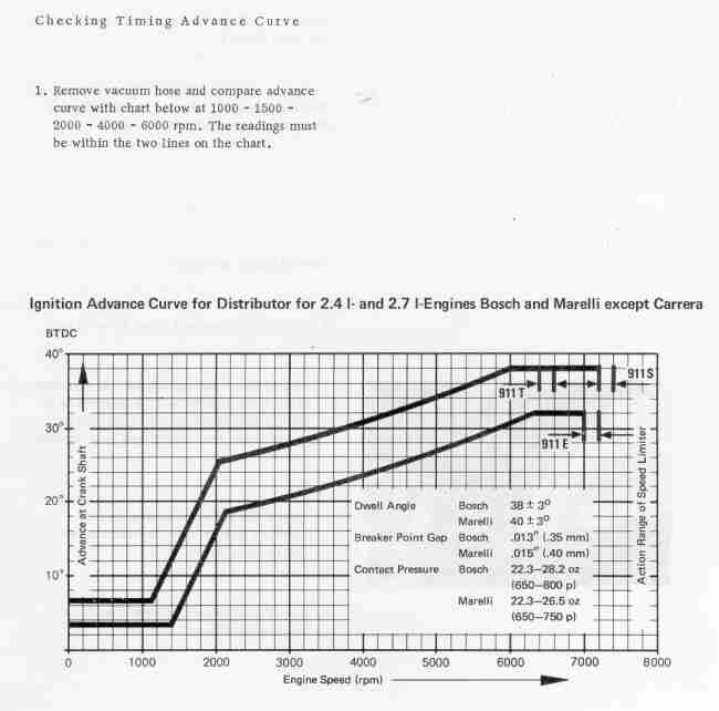 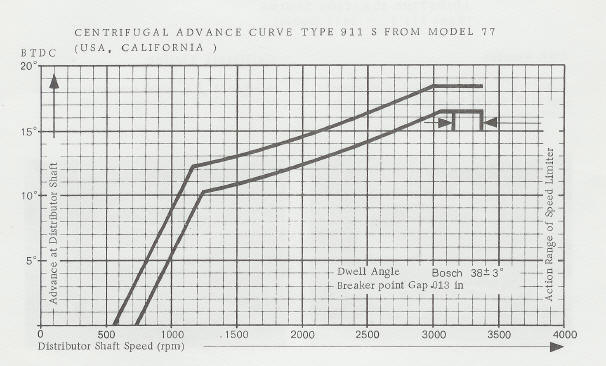 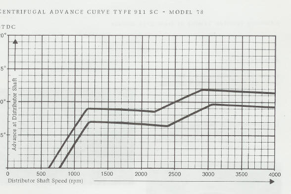
|
   |

 
|
  |
Replies
| DNHunt |
Jul 29 2006, 08:59 AM
Post
#2
|
|
914 Wizard? No way. I got too much to learn. Group: Members Posts: 4,099 Joined: 21-April 03 From: Gig Harbor, WA Member No.: 598 |
I'm not sure how much this will help you but, the ignition map I got from Jake from my four was derived from his work with the Mallory dizzy on his 4s. He used a very simple curve with 12 degrees advance at idle to a max of 28 degrees at 2800 rpms. It would look even simpler than the first curve you have because the rate of advance vs rpms is steady. That distributor is pretty accurate but it is still a big compromise. With programmable ignition you can do much more so the map he sent was a lot more complicated.
First he added more total advance in the mid rpms which puts a single hump in the curve similar to the 2 humps in the SC curve. There is also some advance taken out at high rpms to compensate for the high piston speeds in my engine. Next there is some retard of the curve at high manifold atmospheric pressure (lower vacuum, the throttle plate is letting more air and load is higher) to avoid misfires. Finally there is more advance in areas of the map where manifold pressure is lower (higher vacuum, throttle plate closed or cracked a little). Remember that the advance numbers are relative to where the sensor is. Whatever correction there is for the sensor and missing tooth relative to TDC has to be accounted for in the software or in the values in the map. I'd start with one of the curves and put the values in the graph in the cells on the map in an area where the engine is under moderate load. Then I'd add a couple of degrees in the mid rpms and back out a couple at high rpms. This curve just gets repeated in the cells above and below with the exception that it slightly flattened above the first set of entries and more exaggerrated below. to compensate for air pressure changes. Pay attention to cylinder temps and listen for pinging and adjust. It's probably best to start a little retarded and add advance. Dave Attached image(s) 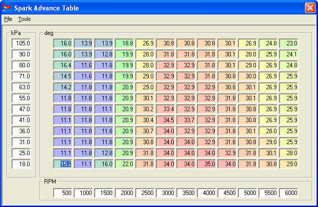
|
|
|
|
Posts in this topic
 Dr Evil I need info/help on how to generate an advance curve with MAP Jul 28 2006, 10:00 PM
 DNHunt This is a quess. Consider it a mental exercise and... Jul 29 2006, 10:27 AM Dr Evil Hey Dave, thanks for the info. I am heading out of... Jul 29 2006, 12:54 PM TimT Didnt you just ask this question a few weeks ago? ... Jul 29 2006, 01:17 PM Dr Evil It is possibel that I did ask this or a similar qu... Jul 29 2006, 01:20 PM fiid There is an excellent thread on this topic on the ... Jul 29 2006, 03:36 PM
 Dr Evil Dave and Fiid,
the info you guys posted is spot on... Jul 31 2006, 09:11 AM
Dr Evil Dave and Fiid,
the info you guys posted is spot on... Jul 31 2006, 09:11 AM |
1 User(s) are reading this topic (1 Guests and 0 Anonymous Users)
0 Members:

|
Lo-Fi Version | Time is now: 5th July 2025 - 03:11 AM |
Invision Power Board
v9.1.4 © 2025 IPS, Inc.