|
|
|
Porsche, and the Porsche crest are registered trademarks of Dr. Ing. h.c. F. Porsche AG.
This site is not affiliated with Porsche in any way. Its only purpose is to provide an online forum for car enthusiasts. All other trademarks are property of their respective owners. |
|
|


| Scott S |
 Mar 17 2014, 04:50 PM Mar 17 2014, 04:50 PM
Post
#1
|
|
Small Member  Group: Members Posts: 1,698 Joined: 30-April 03 From: Colorado Member No.: 633 |
Hi All -
I am going to use a 911 heated window switch to control the fan on my oil cooler. I am trying to verify the different tabs on the back of the switch. Here is a diagram of the back: 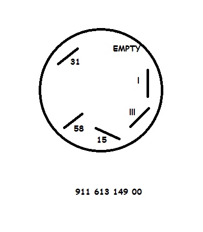 I am guessing that the numerical definitions are standard for all porsche switches - but I dont want to burn up the switch or wiring by making this assumption. Here is how I think things should go: 31 = Ground 58 = light inside the switch <-- is this + or - ? 15 = keyed power I = Load/Accessory #1 III = Load/Accesory #2 Can anyone verify? Also, is #58 a positive or negative lead? When installing a standard off the shelf FLAPS rocker switch, the lead to make it illuminate is negative. However, those types of switches do not have a ground - they just interrupt the power lead to the accessory. On a side note, this is a single postion pull switch - weird that is has what appears to be two load "outputs". Thanks a million for any help!! Scott S |
   |

 
|
Posts in this topic
 Scott S Wiring Help - Identifying switch inputs Mar 17 2014, 04:50 PM
 barefoot
Hi All -
I am going to use a 911 heated window sw... Mar 22 2014, 04:21 PM
barefoot
Hi All -
I am going to use a 911 heated window sw... Mar 22 2014, 04:21 PM Cap'n Krusty If this were my project, I'd put a temperature... Mar 22 2014, 05:48 PM
  |
1 User(s) are reading this topic (1 Guests and 0 Anonymous Users)
0 Members:

|
Lo-Fi Version | Time is now: 13th July 2025 - 07:19 PM |
Invision Power Board
v9.1.4 © 2025 IPS, Inc.