|
|
|
Porsche, and the Porsche crest are registered trademarks of Dr. Ing. h.c. F. Porsche AG.
This site is not affiliated with Porsche in any way. Its only purpose is to provide an online forum for car enthusiasts. All other trademarks are property of their respective owners. |
|
|

  |

| Jeffs9146 |
 Aug 1 2011, 10:23 PM Aug 1 2011, 10:23 PM
Post
#61
|
|
Ski Bum  Group: Members Posts: 4,062 Joined: 10-January 03 From: Discovery Bay, Ca Member No.: 128 |
By the way, I did a compression check and it looks great!!
#1 142 #2 145 #3 150 #4 145 #5 140 #6 145 This was a cold test and there aren't any fuel leaks.........yet!!? (IMG:style_emoticons/default/beerchug.gif) |
   |

 
|
| Mike Bellis |
Aug 1 2011, 10:43 PM
Post
#62
|
|
Resident Electrician Group: Members Posts: 8,348 Joined: 22-June 09 From: Midlothian TX Member No.: 10,496 Region Association: None |
I can fix it if I can find a schematic... I'll keep looking online
|
|
|
|
| Jeffs9146 |
Aug 1 2011, 10:46 PM
Post
#63
|
|
Ski Bum Group: Members Posts: 4,062 Joined: 10-January 03 From: Discovery Bay, Ca Member No.: 128 |
It looks like the problem is in this connection from the harness, wire #22 or #15 to the module which goes to the coil!
Attached thumbnail(s) 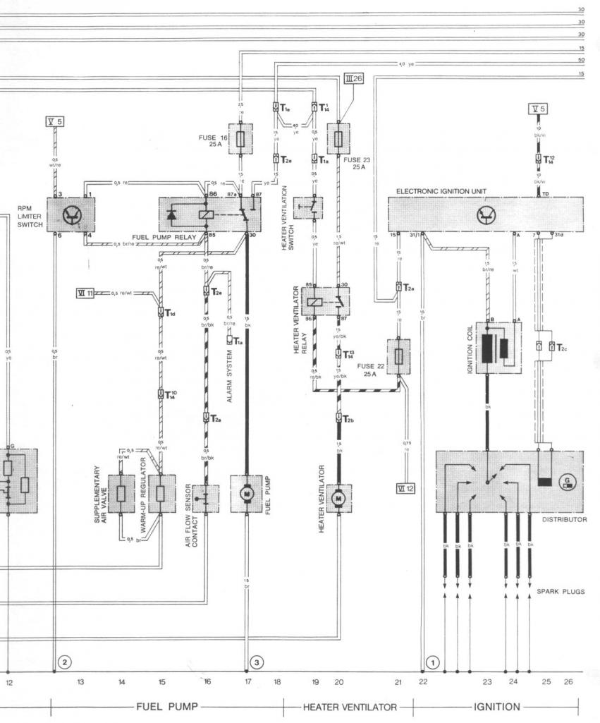
|
|
|
|
| Mike Bellis |
Aug 1 2011, 11:00 PM
Post
#64
|
|
Resident Electrician Group: Members Posts: 8,348 Joined: 22-June 09 From: Midlothian TX Member No.: 10,496 Region Association: None |
Looks like the red wire should go to the battery +. Brown to ground. Looks like the coil is grounded and the ignition module sends + voltage to it to trigger. Black/violet is from key power.
|
|
|
|
| Jeffs9146 |
Aug 1 2011, 11:11 PM
Post
#65
|
|
Ski Bum Group: Members Posts: 4,062 Joined: 10-January 03 From: Discovery Bay, Ca Member No.: 128 |
ok I will check the bl/v and the R+ tomorrow! So does it matter where the ignition BL/VI comes from?
|
|
|
|
| Mike Bellis |
Aug 1 2011, 11:20 PM
Post
#66
|
|
Resident Electrician Group: Members Posts: 8,348 Joined: 22-June 09 From: Midlothian TX Member No.: 10,496 Region Association: None |
QUOTE(Jeffs9146 @ Aug 1 2011, 10:11 PM)  ok I will check the bl/v and the R+ tomorrow! So does it matter where the ignition BL/VI comes from? I wired it on the 14 pin plug. Just make sure I matched it up correctly. On the 914 the black/violet is the tach. The solid black should connect to the black/violet on the 911 wiring. If I'm reading the schematic correctly. You can test power there. It should turn on with the key and remain hot while cranking. |
|
|
|
| Mike Bellis |
Aug 1 2011, 11:23 PM
Post
#67
|
|
Resident Electrician Group: Members Posts: 8,348 Joined: 22-June 09 From: Midlothian TX Member No.: 10,496 Region Association: None |
Follow the "V5" connection on the 911 wiring diagram to make sure I'm correct (above the ignition module).
|
|
|
|
| Jeffs9146 |
Aug 1 2011, 11:49 PM
Post
#68
|
|
Ski Bum Group: Members Posts: 4,062 Joined: 10-January 03 From: Discovery Bay, Ca Member No.: 128 |
I couldn't find any of the diagrams on Pelican that includes the track of the V5 wire!? (IMG:style_emoticons/default/WTF.gif)
Pelican Parts Diagrams Link |
|
|
|
| SirAndy |
Aug 2 2011, 12:26 AM
Post
#69
|
|
Resident German Group: Admin Posts: 42,469 Joined: 21-January 03 From: Oakland, Kalifornia Member No.: 179 Region Association: Northern California |
QUOTE(Jeffs9146 @ Aug 1 2011, 08:49 PM) I found the original fuel pump relay and I was thinking that maybe the fuse block that supplies that power is also where the coil gets its ign source??? Aehmm ... Are you talking about the silver box in the pic? (IMG:style_emoticons/default/idea.gif) If so, that's not a fuel pump relay. It says in big (German) letters "Heckscheiben-Heizregler"!!! Which means "Rear window heater regulator" ... (IMG:style_emoticons/default/shades.gif) (IMG:http://www.914world.com/bbs2/uploads/post-128-1312257473_thumb.jpg) |
|
|
|
| Jeffs9146 |
Aug 2 2011, 02:18 AM
Post
#70
|
|
Ski Bum Group: Members Posts: 4,062 Joined: 10-January 03 From: Discovery Bay, Ca Member No.: 128 |
(IMG:style_emoticons/default/drunk.gif) See thats why we love you Andy!@!
Everyone needs a transelator once in a while (IMG:style_emoticons/default/aktion035.gif) |
|
|
|
| Cairo94507 |
Aug 2 2011, 07:32 AM
Post
#71
|
|
Michael Group: Members Posts: 10,609 Joined: 1-November 08 From: Auburn, CA Member No.: 9,712 Region Association: Northern California |
Jeff:
Does your car have a heated rear window? I did not notice when I was there. God luck and I hope it starts and runs like a CIS should. Michael |
 |
|
| Jeffs9146 |
Aug 2 2011, 08:07 AM
Post
#72
|
|
Ski Bum Group: Members Posts: 4,062 Joined: 10-January 03 From: Discovery Bay, Ca Member No.: 128 |
QUOTE Does your car have a heated rear window? I did not notice when I was there. No that part was from the 911 3.0L car! |
|
|
|
| Jeffs9146 |
Aug 2 2011, 09:27 AM
Post
#73
|
|
Ski Bum Group: Members Posts: 4,062 Joined: 10-January 03 From: Discovery Bay, Ca Member No.: 128 |
OK I traced down the BL/Vi wire and it goes to the small Blue wire in pin #12 of the 914 harness!
Mike, does mean that pin needs to be jumped to the solid Black on the 914 harness? I show the small Blue wire as the K2 Generator Charge Light wire which should go to the Voltage Regulator C2? Attached thumbnail(s) 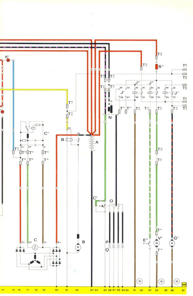
|
|
|
|
| Jeffs9146 |
Aug 2 2011, 12:54 PM
Post
#74
|
|
Ski Bum Group: Members Posts: 4,062 Joined: 10-January 03 From: Discovery Bay, Ca Member No.: 128 |
Bump for more info (IMG:style_emoticons/default/beerchug.gif)
|
|
|
|
| Jeffs9146 |
Aug 2 2011, 05:07 PM
Post
#75
|
|
Ski Bum Group: Members Posts: 4,062 Joined: 10-January 03 From: Discovery Bay, Ca Member No.: 128 |
I spent most of the day looking at the full sized 75 Current Flow Diagram showing where the flow comes from and goes to! It looks like the blue wire connects to K2 (generator charge light) then flows to K16 then G1 then K3 back up to G5 which is the tach and is connected to the black/violet side of the coil!
The blue wire gets its power from the voltage regulator C2 and since I do not have a fuse panel, hence no voltage regulator, then I am going to guess that the blue wire needs to be fed power from the D+ main red wire from the generator C! Any thoughts?? (IMG:style_emoticons/default/idea.gif) |
|
|
|
| Mike Bellis |
Aug 2 2011, 05:49 PM
Post
#76
|
|
Resident Electrician Group: Members Posts: 8,348 Joined: 22-June 09 From: Midlothian TX Member No.: 10,496 Region Association: None |
QUOTE(Jeffs9146 @ Aug 2 2011, 04:07 PM) I spent most of the day looking at the full sized 75 Current Flow Diagram showing where the flow comes from and goes to! It looks like the blue wire connects to K2 (generator charge light) then flows to K16 then G1 then K3 back up to G5 which is the tach and is connected to the black/violet side of the coil! The blue wire gets its power from the voltage regulator C2 and since I do not have a fuse panel, hence no voltage regulator, then I am going to guess that the blue wire needs to be fed power from the D+ main red wire from the generator C! Any thoughts?? (IMG:style_emoticons/default/idea.gif) The blue wire should get a ground from the requlator when the engine is off. That shouls turn to 12V when running. The light will get ignition power on one side, regulator power on the other. Of course I don't remember how I wired it up. The full color schematic would have been helpful or maybe more beer (IMG:style_emoticons/default/beerchug.gif) Sounds like I may have crossed some wires but I wouldn't know without beeing there. If you find some, the pins can be moved to the correct location without soldering. When following the flow chart, the current stops at the nearest load. In the case of the blue wire, the current stops at the light bulb. All the connections at the bottom of the page are ground. |
|
|
|
| Jeffs9146 |
Aug 2 2011, 06:03 PM
Post
#77
|
|
Ski Bum Group: Members Posts: 4,062 Joined: 10-January 03 From: Discovery Bay, Ca Member No.: 128 |
QUOTE The blue wire should get a ground from the requlator when the engine is off. That shouls turn to 12V when running. The light will get ignition power on one side, regulator power on the other. OK so what you are saying is the Blue wire that is now hooked to the black/violet is wrong! The Black/violet needs to be disconected from the blue wire and run to a switched 12v source in the harness that stays on with the starter running? (IMG:style_emoticons/default/idea.gif) |
|
|
|
| Mike Bellis |
Aug 2 2011, 06:14 PM
Post
#78
|
|
Resident Electrician Group: Members Posts: 8,348 Joined: 22-June 09 From: Midlothian TX Member No.: 10,496 Region Association: None |
QUOTE(Jeffs9146 @ Aug 2 2011, 05:03 PM) QUOTE The blue wire should get a ground from the requlator when the engine is off. That shouls turn to 12V when running. The light will get ignition power on one side, regulator power on the other. OK so what you are saying is the Blue wire that is now hooked to the black/violet is wrong! The Black/violet needs to be disconected from the blue wire and run to a switched 12v source in the harness that stays on with the starter running? (IMG:style_emoticons/default/idea.gif) Black/Violet on the 914 is the input to the tach. Black/Violet on the 911 not exactly sure, could be tach. Blue on the 911 goes to the alt lamp on the 914 Looks like the blue wire on the 914 to the lamp 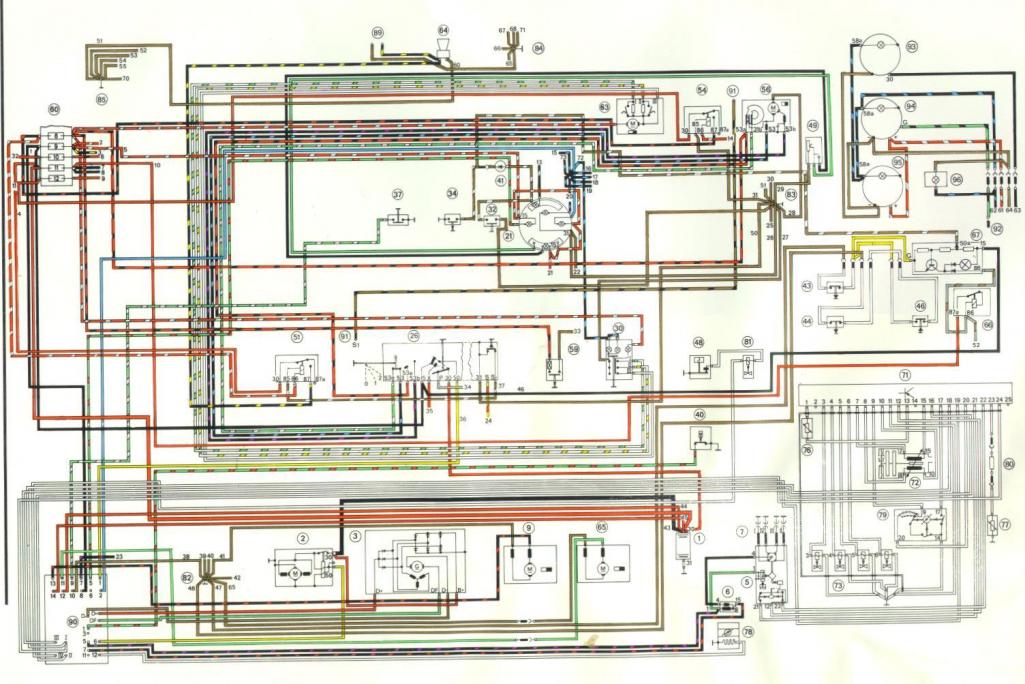 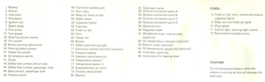 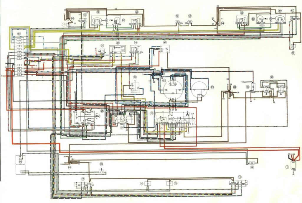 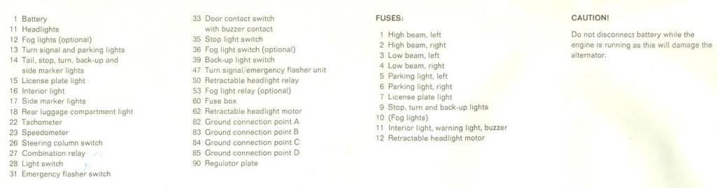 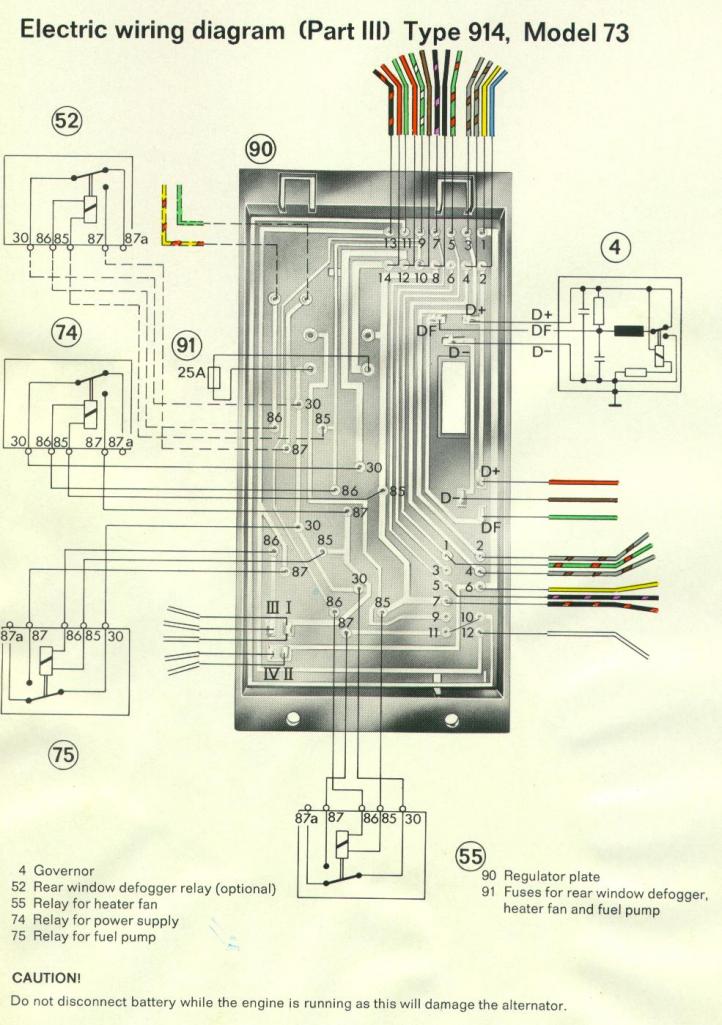 |
|
|
|
| Jeffs9146 |
Aug 2 2011, 06:39 PM
Post
#79
|
|
Ski Bum Group: Members Posts: 4,062 Joined: 10-January 03 From: Discovery Bay, Ca Member No.: 128 |
Right! So Blue on 914 is not good for Black/Violet Ign Module!
I will go and check! I will put the Blue 914 to the Blue 911 Black/Violet 914 to the Black/Violet 911 and that should fix it (IMG:style_emoticons/default/shades.gif) |
|
|
|
| Mike Bellis |
Aug 2 2011, 09:10 PM
Post
#80
|
|
Resident Electrician Group: Members Posts: 8,348 Joined: 22-June 09 From: Midlothian TX Member No.: 10,496 Region Association: None |
Jeff got it running! (IMG:style_emoticons/default/piratenanner.gif) He found an extra power plug I missed. (IMG:style_emoticons/default/dry.gif)
Waiting on video... |
|
|
|
|
1 User(s) are reading this topic (1 Guests and 0 Anonymous Users)
0 Members:

|
Lo-Fi Version | Time is now: 2nd April 2026 - 09:10 AM |
Invision Power Board
v9.1.4 © 2026 IPS, Inc.