|
|
|
Porsche, and the Porsche crest are registered trademarks of Dr. Ing. h.c. F. Porsche AG.
This site is not affiliated with Porsche in any way. Its only purpose is to provide an online forum for car enthusiasts. All other trademarks are property of their respective owners. |
|
|

  |

| JRust |
 Feb 20 2010, 05:20 PM Feb 20 2010, 05:20 PM
Post
#1
|
|
914 Guru  Group: Members Posts: 6,305 Joined: 10-January 03 From: Corvallis Oregon Member No.: 129 Region Association: Pacific Northwest |
I've had my gages out for a while. Just putting my interior back in the LE. Went to do the gages & while there are only so many options. There are a few different combinations. Meaning I would probably get them wrong. Figured to see if anyone had a diagram for them
|
   |

 
|
| rick 918-S |
Feb 20 2010, 05:25 PM
Post
#2
|
|
Hey nice rack! -Celette Group: Members Posts: 20,442 Joined: 30-December 02 From: Now in Superior WI Member No.: 43 Region Association: Northstar Region |
QUOTE(JRust @ Feb 20 2010, 05:20 PM)  I've had my gages out for a while. Just putting my interior back in the LE. Went to do the gages & while there are only so many options. There are a few different combinations. Meaning I would probably get them wrong. Figured to see if anyone had a diagram for them I think there are diagrams on the bird board. I think... (IMG:style_emoticons/default/idea.gif) |
|
|
|
| Todd Enlund |
Feb 20 2010, 05:26 PM
Post
#3
|
|
Resident Photoshop Guru Group: Members Posts: 3,251 Joined: 24-August 07 From: Laurelhurst (Portland), Oregon Member No.: 8,032 Region Association: Pacific Northwest |
QUOTE(JRust @ Feb 20 2010, 03:20 PM) I've had my gages out for a while. Just putting my interior back in the LE. Went to do the gages & while there are only so many options. There are a few different combinations. Meaning I would probably get them wrong. Figured to see if anyone had a diagram for them Take your pick: http://www.pelicanparts.com/914/914_electrical_diagrams.htm |
|
|
|
| JRust |
Feb 20 2010, 05:44 PM
Post
#4
|
|
914 Guru Group: Members Posts: 6,305 Joined: 10-January 03 From: Corvallis Oregon Member No.: 129 Region Association: Pacific Northwest |
I was hoping for a nice picture of the backside hooked up (IMG:style_emoticons/default/confused24.gif) . Using that wiring diagram will take brain power (IMG:style_emoticons/default/dry.gif) . Everyone should know by now I am in short supply (IMG:style_emoticons/default/headbang.gif)
|
|
|
|
| JeffBowlsby |
Feb 20 2010, 08:13 PM
Post
#5
|
|
914 Wiring Harnesses Group: Members Posts: 8,490 Joined: 7-January 03 From: San Ramon CA Member No.: 104 Region Association: None |
Ya mean like this here? From my 914 Classic site:
Attached thumbnail(s) 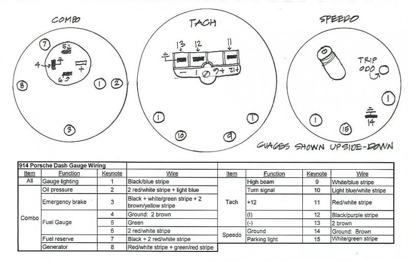
|
|
|
|
| JRust |
Feb 20 2010, 08:22 PM
Post
#6
|
|
914 Guru Group: Members Posts: 6,305 Joined: 10-January 03 From: Corvallis Oregon Member No.: 129 Region Association: Pacific Northwest |
QUOTE(Jeff Bowlsby @ Feb 20 2010, 06:13 PM) Ya mean like this here? From my 914 Classic site: Yes Jeff that is perfect! Thanks I pulled the gage partially out on my 73. Only problem is the combo gage is different. So I did need this for that one. |
|
|
|
| watsonrx13 |
Feb 21 2010, 06:58 AM
Post
#7
|
|
Advanced Member Group: Members Posts: 2,734 Joined: 18-February 03 From: Plant City, FL Member No.: 312 Region Association: South East States |
Jamie, this is the diagram I made for my '74, hope it helps.
 -- Rob |
|
|
|
| StratPlayer |
Feb 21 2010, 11:23 AM
Post
#8
|
|
StratPlayer Group: Members Posts: 3,270 Joined: 27-December 02 From: SLC, Utah Member No.: 27 Region Association: Rocky Mountains |
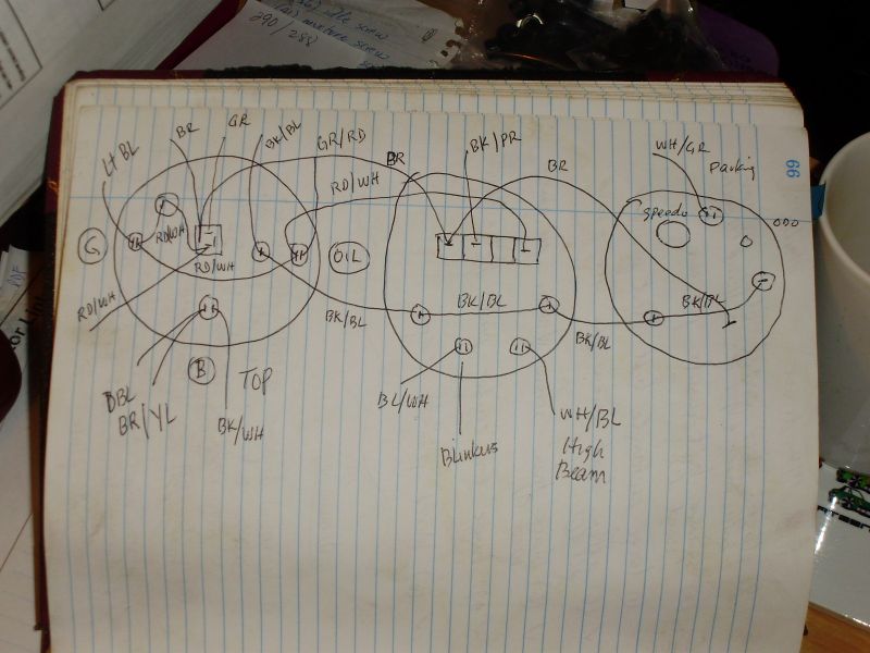
combo gauge setup
Attached image(s) 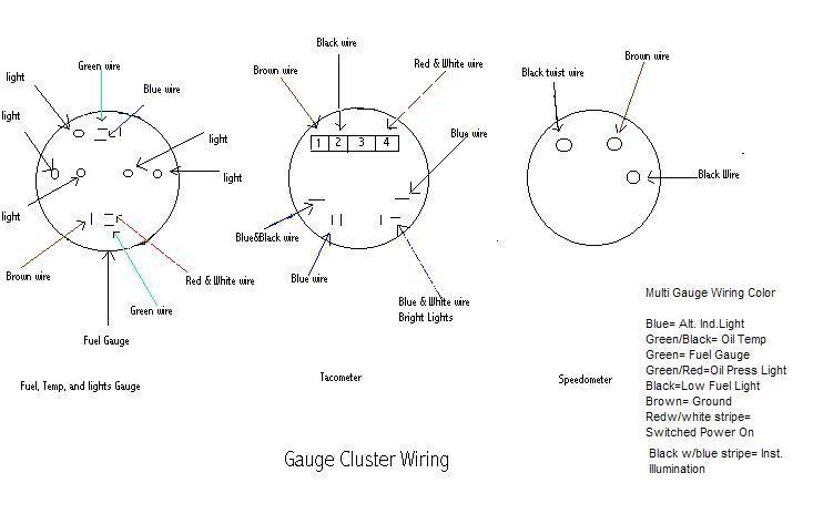
|
|
|
|
| JRust |
Feb 21 2010, 11:42 AM
Post
#9
|
|
914 Guru Group: Members Posts: 6,305 Joined: 10-January 03 From: Corvallis Oregon Member No.: 129 Region Association: Pacific Northwest |
I got it off of Jeff's diagram. Thanks for all the help guys. Still a ways from being able to actualy test it (IMG:style_emoticons/default/dry.gif) . It is hooked up right though thanks to your help (IMG:style_emoticons/default/aktion035.gif)
|
|
|
|
| flipb |
Mar 9 2010, 01:00 PM
Post
#10
|
|
Senior Member Group: Members Posts: 1,721 Joined: 2-September 09 From: Fairfax, VA Member No.: 10,752 Region Association: MidAtlantic Region |
My gauges have some wiring quirks that I'm hoping to address soon. This thread will be a great help.
Two quick questions: 1. I know of at least one wire back there that shorted out and melted its sheath... What gauge wire do I need to replace it? 2. Is it necessary to remove the dash bottom to access the various electrical hookups on the headlight switch? The extent of my electrical experience has been replacing fixtures and outlets in my house. Appreciate any additional tips for the clueless. |
|
|
|
| McMark |
Mar 9 2010, 01:38 PM
Post
#11
|
|
914 Freak! Group: Retired Admin Posts: 20,179 Joined: 13-March 03 From: Grand Rapids, MI Member No.: 419 Region Association: None |
1. Most wires are 18g, but some are larger.
2. The headlight switch has a lot of connections. If you drop the relay panel (two screws), unscrew the knob and then unscrew the escutcheon (the small aluminum ring) which holds the switch onto the dash, you can then pull the switch down enough to see what is what. |
|
|
|
| nivekdodge |
Jun 16 2022, 08:03 PM
Post
#12
|
|
Member Group: Members Posts: 248 Joined: 28-August 21 From: Pittsburgh Pa Member No.: 25,860 Region Association: MidAtlantic Region |
QUOTE(Jeff Bowlsby @ Feb 20 2010, 10:13 PM) Ya mean like this here? From my 914 Classic site: Jeff I have a dash and chunk of harness out of a 72 that im going to try to wire into my 74. will the wire colors match up? |
|
|
|
| GeorgeKopf |
Jun 16 2022, 08:15 PM
Post
#13
|
|
Member Group: Members Posts: 172 Joined: 9-February 21 From: Princeton, NJ Member No.: 25,186 Region Association: MidAtlantic Region |
This is mine from a 73.
 |
|
|
|
| JeffBowlsby |
Jun 16 2022, 09:04 PM
Post
#14
|
|
914 Wiring Harnesses Group: Members Posts: 8,490 Joined: 7-January 03 From: San Ramon CA Member No.: 104 Region Association: None |
QUOTE(nivekdodge @ Jun 16 2022, 07:03 PM) QUOTE(Jeff Bowlsby @ Feb 20 2010, 10:13 PM) Ya mean like this here? From my 914 Classic site: Jeff I have a dash and chunk of harness out of a 72 that im going to try to wire into my 74. will the wire colors match up? Different gauges, different wiring |
|
|
|
| GeorgeKopf |
Jun 29 2022, 07:09 PM
Post
#15
|
|
Member Group: Members Posts: 172 Joined: 9-February 21 From: Princeton, NJ Member No.: 25,186 Region Association: MidAtlantic Region |
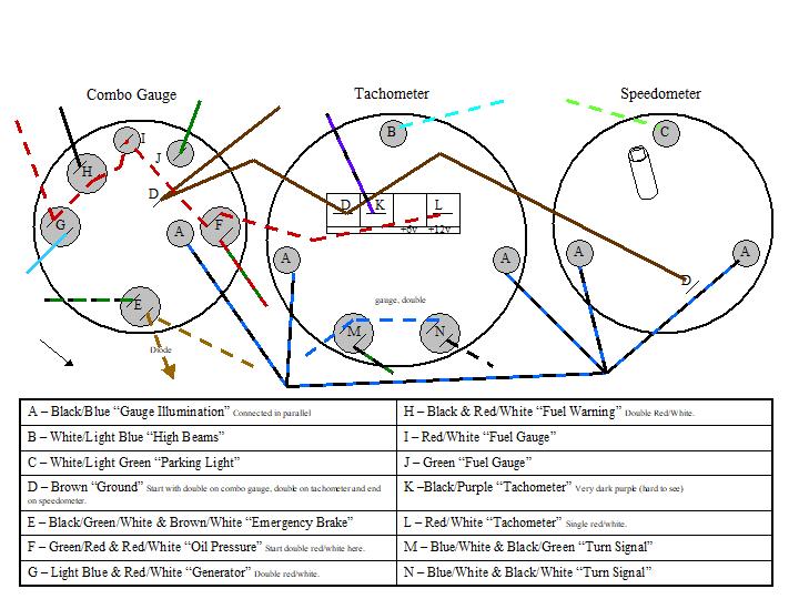
QUOTE(JRust @ Feb 20 2010, 05:44 PM) I was hoping for a nice picture of the backside hooked up (IMG:style_emoticons/default/confused24.gif) . Using that wiring diagram will take brain power (IMG:style_emoticons/default/dry.gif) . Everyone should know by now I am in short supply (IMG:style_emoticons/default/headbang.gif) @JRust I found some pictures of the gauges that show the connections pretty clearly. The lights are not plugged in (blue/black wire), so the empty sockets are the dash lights. Combo Gauge 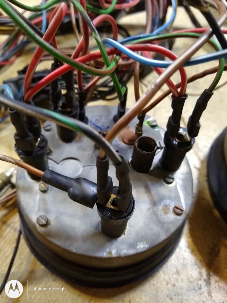 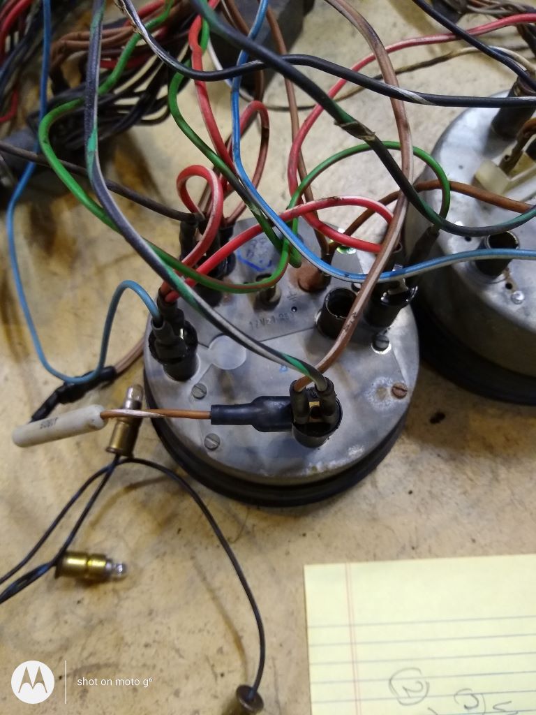 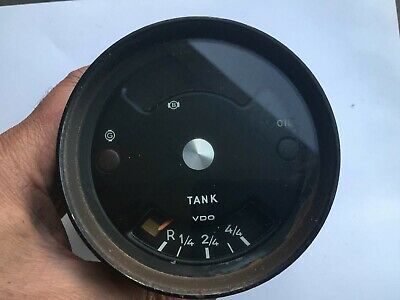 Speedometer (The black cable on the right is the tripometer reset cable). 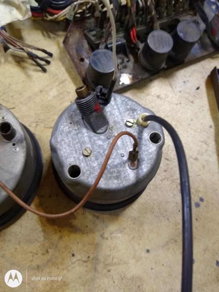 Tachometer 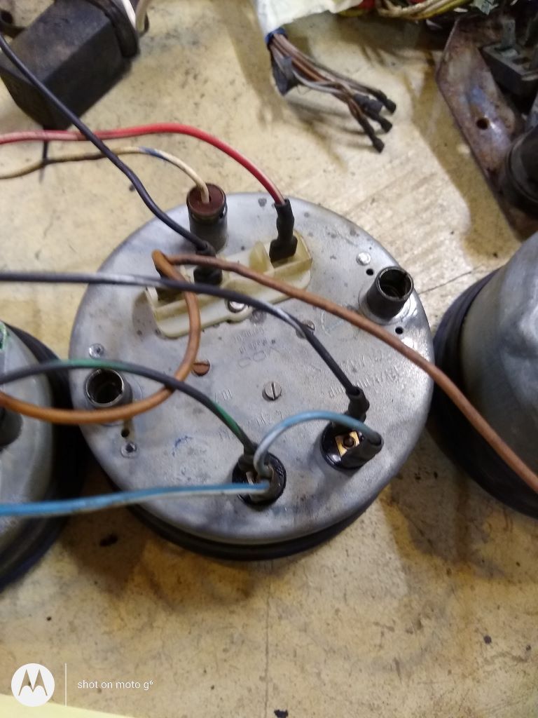 Good Luck. |
|
|
|
|
1 User(s) are reading this topic (1 Guests and 0 Anonymous Users)
0 Members:

|
Lo-Fi Version | Time is now: 4th May 2024 - 11:54 PM |
Invision Power Board
v9.1.4 © 2024 IPS, Inc.