|
|
|
Porsche, and the Porsche crest are registered trademarks of Dr. Ing. h.c. F. Porsche AG.
This site is not affiliated with Porsche in any way. Its only purpose is to provide an online forum for car enthusiasts. All other trademarks are property of their respective owners. |
|
|

  |

| jim912928 |
 Dec 4 2010, 12:31 AM Dec 4 2010, 12:31 AM
Post
#1
|
|
Senior Member  Group: Members Posts: 1,487 Joined: 8-January 04 From: Granger, IN Member No.: 1,536 Region Association: Upper MidWest |
Well, I have all of the mechanical work done for my 3.2l motronic conversion. Now I'm trying to figure out the wiring. I purchased the Patrick MotorSports conversion harness a few years back. It allows me to eliminate the relay board. However, electrical is not my forte...so I have some real questions on the "trunk" wires from the 3.2l harness and what to do with them. The engine, dme and wiring harness are all from the same car. So, here are my questions and you can relate them to the pictures as shown:
1. picture named "DME help" circle #1: by the dme connector...there are two little stub connections that seem to come out of the DME connector and both wires are brown....do these need to go to anything? 2. picture named "Trunk help" circle #2: I marked these fuel pump...do I cap these because I'm using the 914 wiring or do I need to connect them somewhere? 3. picture named "Trunk help" circle #3: I marked this positive battery...does the 914 harness cover this or do I need to connect it to the battery also? 3. picture named "Trunk help" circle #4: green and green/yellow wire...have no clue what this is? 4. picture named "Trunk help" circle #5: black wire by the wires I labeled "fuel pump"...have no clue what this is? 5. picture named "Trunk help" circle #6: white connector with a black, black/purple and yellow wire...have no clue what this is? I also would like to know where you usually mount the DME and where do you pass it through from the passenger compartment into the engine compartment..and once on the engine compartment side...where do you route it up to the engine? Have pics from those angles? Thanks all in advance! Jim DME help: 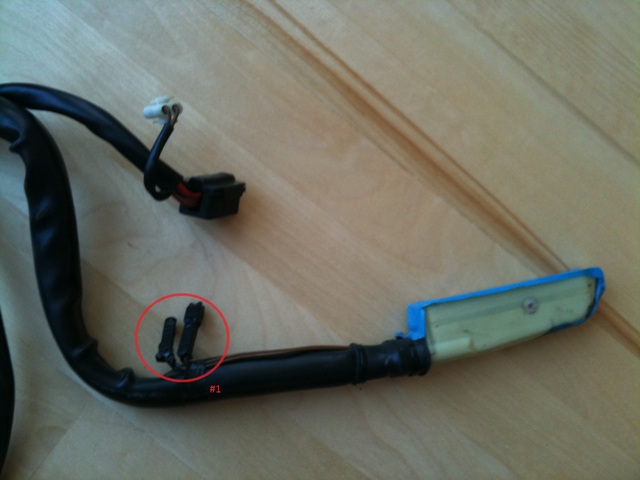 Trunk help: 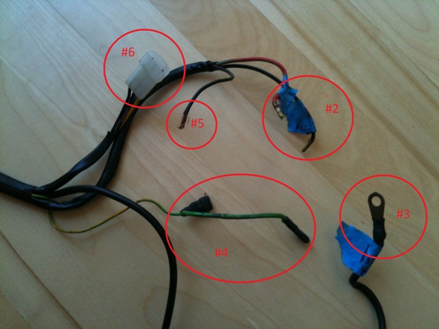 |
   |

 
|
| John |
Dec 4 2010, 12:41 AM
Post
#2
|
|
member? what's a member? Group: Members Posts: 3,393 Joined: 30-January 04 From: Evansville, IN (SIRPCA) Member No.: 1,615 Region Association: None |
You are going to need a schematic and follow the wiring diagram.
The Motronic DME Relay powers the Motronic and also controls the fuel pump. (you should be using the 3.2 fuel pump with the 3.2) The ring terminal you show looks like the one that runs back to the starter. + terminal. The terminal ends in pic #2 look like they terminate at fuses in the 911 front trunk. One very well may be for the fuel pump, but it is at the fuse end not the pump end. I typically drill the hole for the harness on the passenger side of the firewall. It's really up to you where you drill your hole. I mount the DME either under the passenger seat or on the firewall behind the passenger seat. I'm not sure (from memory) where the short pigtails go, but in general (on a Porsche) if it is a solid brown wire, chances are that it is a ground. |
|
|
|
| shoguneagle |
Dec 4 2010, 04:59 AM
Post
#3
|
|
shoguneagle Group: Members Posts: 1,180 Joined: 3-January 03 From: CA, OR, AZ (CAZOR); New Mexico Member No.: 84 Region Association: Northern California |
Whoa!!! Let us stop before going any further! We will get you through this wiring and it is not a great problem; we just have to take a little time and see what is going on and how we can get everything tied together.
John is right. You have to use the 3.2 fuel pump, altitude sensor, and fuel pump/DME relay. These control everything regarding the engine fuel and management system. I do not know what the Patrick Wire Harness does but I believe it ties some of the engine requirements from the engine to the 914 harness thus eliminating the fuel pump fuse/relay, power relay, rear window defrost, heater fan fuse, heater fan, and a couple of items that relate to the -4 fuel injection system. First, there are several items that need to be discussed: tachometer, fuel pump and fusing, key power, heater fan (if retained), starting, and maybe a couple of other things. What exactly does the Patrick Wiring do and what does it change in routing wiring from the engine to the 914 wiring harness (i.e. the 14-pin connector)? Need to know from where to where on the wiring harness 14-pin (engine to 914). Second, did you get the tachometer, altitude sensor, fuel pump/dme relay with the engine? The probably other considerations but for now the above is enough. I will go get my schematics and notes from the garage and see what I can do to further help you out. #6 above has a couple of things going through it; two wires (one of the black ones and the black/violet got to the tachometer from the DME and then back to the DME; I will have to get with my notes to see where the other black wire and the yellow wire goes and their functions. Once I get my notes I can tell you exactly what does what and then we can adjust accordingly. How do I know? I am currently doing the final tracing and validation of my wiring for a 3.2 1987 Carrera engine conversion. You should get a wiring schematic (look at Pelican Board under wiring diagrams for the appropriate 914; you should have a volt/ohm meter for tracing back different wiring. The key is the 14-pin connector and once you have that setup (Patrick Wiring harness adaptor, or direct wiring) the balance falls into place. First, help me understand what the Patrick Adaptor does exactly. For a start, the 3.2 engine 14-pin connector has the following pin assignments: 1 - Yellow Starter 2 - Red Battery B+/Alternator 3 - Green/black Oil temperature 4 - Green/red Oil pressure 5 - Red/green Ign to Backup Light switch 6 - Gray/brown Backup lights to backup light switch 7 - Open 8 - Brown/black Temperature switch to fresh air blower 9 - Green/white Oil pressure idiot light 10 - Open 11 - Blue Alternator control light (generator light) 12 - Open 13 - Black/yellow Fresh air blower power 14 - Red Battery/Alternator B+ Take the above wiring pins at the 14-pin connector with a grain of salt and verify them for your own comfort zone. These can be traced back through the engine harness for verification; REMEMBER: DO NOT TRY TO VERIFY WITH OHM METER WITH THE HARNESS CONNECTED TO THE DME COMPUTER; ;YOU WILL RUIN THE COMPUTER!!!! The other piece of information you may need is the computer connector pin assignment. Enough for now; if you do not need this information, please disregard. Steve Hurt |
|
|
|
| jim912928 |
Dec 4 2010, 09:11 AM
Post
#4
|
|
Senior Member Group: Members Posts: 1,487 Joined: 8-January 04 From: Granger, IN Member No.: 1,536 Region Association: Upper MidWest |
Thanks for the input so far. Here is additional information that I left out late last night when posting:
1. I am using the original fuel pump from the 911 2. I am using the original Tach from the 911 3. I have and will be using the original DME, altitude sensor and DME relay The Patrick Motorsports part is a pre-built jumper harness (14 pin to 14 pin) specifically designed to connect the 3.2l 14-pin connector engine harness to the 914-4 14-pin harness (and thus eliminating the relay board). It has additional leads if I want to add an oil pressure gauge, oil temp gauge and the heater blower (which I will keep being in the midwest). It's already bundled and shrink wrapped so taking it apart to see how it was pinned would most likely wreck it (remember, I'm not a wiring guy...about all i'm good for is connect/disconnect). I can visualize that the 914 side of the connector has pins coming out at 1,2,3,4,5,8,9,12,14 and the 3.2l side has pins at 1,2,3,4,5,6,9,11,14. Thanks again for the help! |
|
|
|
| shoguneagle |
Dec 4 2010, 01:37 PM
Post
#5
|
|
shoguneagle Group: Members Posts: 1,180 Joined: 3-January 03 From: CA, OR, AZ (CAZOR); New Mexico Member No.: 84 Region Association: Northern California |
Hi Jim,
The info I have given you thus far is not to overwhelm you but to give you valuable information so you can check the resistance path to ensure you have everything connected right. This is info you need to make sure the connections are done right. 1. Original fuel pump from the 911 (Motronic) is what to use. 2. Original tach from 911 (Motronic) is what to use. 3. DME, altitude sensor and DME relay correct. You have just told me that the connection jumper (Patrick) changes and matches the engine connections to the 914 car connections. This I needed to know as we proceed along this path including the oil temperature and oil pressure. The only thing possibly not covered is the backup light switch and light wiring which on the 3.2 should be going through the engine harness on the 3.2 side of the house; 914 side goes through the wiring harness of the car; you can go either way on this wiring - look and see what Patrick has done in their jumper. I wired my 14-pin connector in the car side to match the engine connector requirements and we both have the same wiring matches. I am not a electrical wiring expert, but I needed the information to trace the resistance path of the engine harness to make sure I was connecting items correctly. This does not mean you have to check everything but there will be an occasion where you may need the information. Now that I understand what you have and have covered the basis, I will go out and match your requested info to the pictures and try to get as much info as possible. I am placing the DME, altitude sensor and fuel pump/DME relay between the seats after coming through the right side of the lower firewall. This allows the total harness to run forward to the battery, switch, and tach. I also have a very good diagram on how the connections are made. I will see if I can find it for you. Now to get you the info in your pictures. Steve Hurt |
|
|
|
| mepstein |
Dec 4 2010, 02:10 PM
Post
#6
|
|
914-6 GT in waiting Group: Members Posts: 20,701 Joined: 19-September 09 From: Landenberg, PA/Wilmington, DE Member No.: 10,825 Region Association: MidAtlantic Region |
This is valuable information for all of us doing the 3.2 swap. I will be using the Patric adaptor as well. Thanks! Mark
|
|
|
|
| shoguneagle |
Dec 4 2010, 02:49 PM
Post
#7
|
|
shoguneagle Group: Members Posts: 1,180 Joined: 3-January 03 From: CA, OR, AZ (CAZOR); New Mexico Member No.: 84 Region Association: Northern California |
Pictures:
DME help: two brown wires which should be some type of ground; on my harness connected together with a connector. Trunk help (911 reference ??): Now we get into why you need an ohm meter, schematics, etc to make sure the connections are made correctly; can easily verify by a continuity check (resistance path) to the various connection points: #6 - has three wires that you are going to use; two to the tachometer (one of the blacks and the black/violet; you will need to trace these out as follows: Black - from DME - 21 Black/violet - from DME - 11 {reference view as connected to tach} Yellow - from DME - 4 (start only; tap 914 harness) black - I did not use this wire; after separated from the others #5 - looks like a black wire which goes to the "start and run position; tap 914 harness; need to verify this by tracing out back either to the DME relay or possibly to the coil. Also looks like a black wire on #3?? which could be this item. #3 ?? - looks like a red/green wire which should be traced out; coming from DME relay #5 and goes through a 25amp fuse to the fuel pump; I believe you have to put in the fuse in the path to the fuel pump power wire. - looks like a black wire which could be coming from the ignition coil and DME 5; reference back to #5 which could be listed above as the same item. #4 - looks like a green wire??? and cannot tell what is suppose to be. I think you now can see why you need to check the wiring to make sure you have the right connections. Also, the wiring to the tach I did not use the connector shown (does not go to the back of the tach connection). wired in another connector which fit the tach connection and hard wired the shown connector with a bridge like Patrick's. I have a schematic showing the connections and all the items related to the connections needed to be made; has reference to DME, DME relay, etc. I would be happy to send this information to you and should provide a clearer view of how things connect and relate to each other. Steve Hurt |
|
|
|
| shoguneagle |
Dec 4 2010, 03:19 PM
Post
#8
|
|
shoguneagle Group: Members Posts: 1,180 Joined: 3-January 03 From: CA, OR, AZ (CAZOR); New Mexico Member No.: 84 Region Association: Northern California |
Now to give some more back ground from the schematic showing the connections, it is as follows: (I cannot take credit for it but obtained it from one of the excellent threads on Sixer conversions. I wish I could remember who did it and give full credit to where it is deserved). After five years on the project and many sources of information, it is hard to remember who actually provided the information.
After finishing the connections reflected in the drawing or schematic, I will attempt to add it to this thread as an attachment so major documentation is in one area. The only other info you may need is the DME computer pin assignments which can be found in the Bentley Manual. Fuel Pump - located in front trunk; wired to DME Relay #1 with fuse 25amp; red/green wire coming from DME-relay #1 pin Start & Run - Tap into 914 harness - from DME Relay #5 pin; black wire and is also connected to the coil (+) in engine compartment; coil wire at coil is black Battery (B+) - comes from battery and goes to DME Relay #6 pin; red wire which may have to be added into the wiring harness from battery to the DME Relay Start Only - Tap Yellow in 94 harness; start cycle; DME #4 pin (NOT DME (RELAY) Tachometer - one from the car the engine came from - black/violet from DME #21 pin (not DME Relay); need to match with correct pin on the back of the tach (again the need for wiring schematics) - black wire from DME #11 (again not the DME Relay); need to match with correct pin on the back of the tach; power and grounds to the tach are provided on the 914 wiring side of the house Altitude Sensor - connector near the DME/Fuel Pump Relay Socket I have left the 14 pin connection alone since I think the basis of matching 914 wiring to the engine wiring has been provided. Please take everything with alot of "salt" and double check everything as you are doing it. You would be surprised how many times I got off track in wiring my project. Hope this helps. Now to try to attach the schematic of the connections to this thread. If I have problems attaching it, you may contact me anytime and I will send it to you. Jim, contact me off thread and I will make sure you get a copy of the schematic. For 914 wiring diagrams, Pelican has some; I do not know if Road Atlanta has any references. Steve Hurt |
|
|
|
| jim912928 |
Dec 4 2010, 03:54 PM
Post
#9
|
|
Senior Member Group: Members Posts: 1,487 Joined: 8-January 04 From: Granger, IN Member No.: 1,536 Region Association: Upper MidWest |
Steve...sent you a pm with my email. It ha been 5 years since I stripped this harness out of my 84 donor. If I stretch the cable out I believe #3 connected to the positive terminal on the battery. The next bundle back (#2 & #5) connected to the fuse box/relay panel (they are bent that way also). Still can't remember #4. And if the three pin connector (#6) is for the Tach...might the 3rd wire be for the computer assisted shift light indicator (CASIS is what porsche called it) that lights up a "upshift" arror on the Tach?
|
|
|
|
| shoguneagle |
Dec 5 2010, 12:12 AM
Post
#10
|
|
shoguneagle Group: Members Posts: 1,180 Joined: 3-January 03 From: CA, OR, AZ (CAZOR); New Mexico Member No.: 84 Region Association: Northern California |
Jim,
There is an Tach up shift setup but I did not even consider finding it or connecting it. I did not find anything relating to it in the harness on the resistance path checks I did in matching the wiring harness (3.2 engine). I have you a package with the wiring schematic/diagram along with the 3.2 DME computer pin assignments. I also included the tach pin assignments which are as follows for the 3.2 Motronic engine: Power to tach #5 pin on back - provided by the 914 wiring Ground to tach #6 pin on back - provided by the 914 wiring Engine harness black wire to #1 pin on back of tach - from DME pin #22 Engine harness black/violet wire to #2 pin on back of tach - from DME pin #11 Please use an ohm meter to verify the different paths on the engine wire connections in question, and note what they should connect to following the schematic/diagram. this information will provide you with the answers to where what goes where, etc. Package will be in mail Monday Mark, I am sending the same package to you with the same information. |
|
|
|
| jim912928 |
Dec 5 2010, 09:36 AM
Post
#11
|
|
Senior Member Group: Members Posts: 1,487 Joined: 8-January 04 From: Granger, IN Member No.: 1,536 Region Association: Upper MidWest |
Thanks Steve!
|
|
|
|
| mepstein |
Dec 5 2010, 09:37 AM
Post
#12
|
|
914-6 GT in waiting Group: Members Posts: 20,701 Joined: 19-September 09 From: Landenberg, PA/Wilmington, DE Member No.: 10,825 Region Association: MidAtlantic Region |
|
|
|
|

| echocanyons |
Dec 5 2010, 12:07 PM
Post
#13
|
|
Advanced Member Group: Benefactors Posts: 2,117 Joined: 24-December 02 From: Bay Area, CA Member No.: 7 Region Association: Central California |
Great thread.
I am currently doing the same swap, only I had thought tat the PMS jumper got rid of all of the guesswork with the wiring, I guess I was wrong. Pictures of the wiring solutions would be great and would help to eliminate the guess work with folks who do this in the future. |
 |
|
| shoguneagle |
Dec 5 2010, 09:40 PM
Post
#14
|
|
shoguneagle Group: Members Posts: 1,180 Joined: 3-January 03 From: CA, OR, AZ (CAZOR); New Mexico Member No.: 84 Region Association: Northern California |
The Patrick Jumper just takes care of the 14 pin connector; it does not take care of how the wiring goes for fuel pump, key power, starter, fuel pump/DME relay, etc. It appears to be an excellent product and does the job of matching the necessary wire changes involving that connector.
As soon as we get Jim and Mark taken care of and have their feed back, we can put this on the thread. We need to ensure the focus is right and the information is correct as it can be represented. Once this period and information is completed, then I would be happy to send the complete information/drawing/schematic to someone who will put it as an attachment to the thread. Remember we are dealing with the 3.2 Motronic engine and its wiring characteristics/connections. The years I believe are 1984-1989 I will be validating my connections to ensure we are correct and would appreciate info from Jim and Mark after they receive a package I am sending them and validate it. Other considerations should possibly include schematic of fuel pump, DME/fuel pump relay, and wiring considerations as they apply to the connection consideration. If you do not use the Patrick Jumper, then the information I have listed previously that apply to the actual wire changes at the 14-pin connector need to be validated and understood. Some people may choose to use part of the relay board functions; this should be addressed. Again, I want the emphasis should be given to the numerous people who have made this engine change into 914s and early 911s. The schematic/diagram was on one of the older Pelican threads and they should get full credit for their time and efforts in making the drawing. Many people have contributed to threads on all the 914/911 boards and have provided much of the background and insight into the necessary changes. I wish I could remember all their names and the actual work they have done in order to get credit and acknowledgement. Thank you to those "contributors" because I would not have my car conversion almost complete; the schematic/diagram really gave me insight into wiring the 14-pin connector (I did not use Patrick's); how the tach and fuel Pump relay/DME relay were connected and controlled the Motronic fuel injection system; and how the key power (start only, and start/run positions) were connected. There may be other items that are needed into this thread including procedures and what is needed. Hopefully, these will come out as we try to finalize this thread so anyone who is doing/going to do a 3.2 Motronic engine exchange will have some type of up-to-date valid information. If this is the type of information you need/want, then we should take this opportunity to try to document this thread. Remember many people have provided much of the information on 914world, 914club, Pelican (914 and 911 boards) and many others and for these efforts they are the ones who deserve the credit for any final information. They are the ones who have done this activity and did provide information as we may be able to provide here. If you see the need for this info, I will need help from Jim and Mark to make sure it gets completed and listed on the board, or any of the boards we use as members. |
|
|
|
| shoguneagle |
Dec 5 2010, 09:57 PM
Post
#15
|
|
shoguneagle Group: Members Posts: 1,180 Joined: 3-January 03 From: CA, OR, AZ (CAZOR); New Mexico Member No.: 84 Region Association: Northern California |
echocanyons,
Sent an e-mail to you. Steve Hurt |
|
|
|
| mepstein |
Dec 5 2010, 10:12 PM
Post
#16
|
|
914-6 GT in waiting Group: Members Posts: 20,701 Joined: 19-September 09 From: Landenberg, PA/Wilmington, DE Member No.: 10,825 Region Association: MidAtlantic Region |
Don't wait for me. I'm still buying parts for the swap and having rust repaired. Hope to build up car in the spring. Thanks, Mark
|
|
|
|
| jim912928 |
Dec 5 2010, 10:50 PM
Post
#17
|
|
Senior Member Group: Members Posts: 1,487 Joined: 8-January 04 From: Granger, IN Member No.: 1,536 Region Association: Upper MidWest |
I was poking around the pelican site in the 911 forum to see if anybody had a discussion going on for the motronic front wiring harness. Found a link to a site where an individual was doing a 2.7l to 3.2l conversion. So, he had to deal with the DME wiring harness as it wouldn't exist in a 2.7. Click on the link below and scroll about 2/3 of the way down. He'll talk about the DME pins...and then scroll some more and he highlights sections of the front motronic harness and what he did. Just more good info that we can validate in the diagrams.
http://www.pelicanparts.com/MotorCity/marc...ifications.html Jim |
|
|
|
| echocanyons |
Dec 6 2010, 12:01 AM
Post
#18
|
|
Advanced Member Group: Benefactors Posts: 2,117 Joined: 24-December 02 From: Bay Area, CA Member No.: 7 Region Association: Central California |
Thanks Steve.
I plan to have the engine installed and running by the new year so I will detail my wiring experience in this thread as well (if you don't mind Jim). I will be using a 85 model year engine with the PMS jumper harness. |
|
|
|
| Steve |
Dec 6 2010, 12:33 AM
Post
#19
|
|
914 Guru Group: Members Posts: 6,042 Joined: 14-June 03 From: Laguna Niguel, CA Member No.: 822 Region Association: Southern California |
Great info. The wiring is simple. All I did was buy the opposite 14 pin connector from Zims and build a harness to the 3.2 wiring. All I used was the 911 haynes manual and the 914 manual to figure out the wiring. The engine would of started first try if it wasn't for a pinched fuel line under the tank. I also dumped the relay board in the engine compartment and connected everything direct.
|
|
|
|
| jim912928 |
Dec 6 2010, 01:09 AM
Post
#20
|
|
Senior Member Group: Members Posts: 1,487 Joined: 8-January 04 From: Granger, IN Member No.: 1,536 Region Association: Upper MidWest |
Steve from Laguna...since yours is running...could you tell us what you did with the wires on the DME harness that, in a 911, route into the front trunk of the car?
|
|
|
|
|
1 User(s) are reading this topic (1 Guests and 0 Anonymous Users)
0 Members:

|
Lo-Fi Version | Time is now: 23rd May 2026 - 11:32 PM |
Invision Power Board
v9.1.4 © 2026 IPS, Inc.