|
|
|
Porsche, and the Porsche crest are registered trademarks of Dr. Ing. h.c. F. Porsche AG.
This site is not affiliated with Porsche in any way. Its only purpose is to provide an online forum for car enthusiasts. All other trademarks are property of their respective owners. |
|
|

  |

| 914_teener |
 Sep 28 2011, 08:30 PM Sep 28 2011, 08:30 PM
Post
#21
|
|
914 Guru  Group: Members Posts: 5,197 Joined: 31-August 08 From: So. Cal Member No.: 9,489 Region Association: Southern California |
....ok if this works well....I'm headed North to McMark's.
(IMG:style_emoticons/default/popcorn[1].gif) (IMG:style_emoticons/default/popcorn[1].gif) |
   |

 
|
| rwilner |
Sep 29 2011, 08:02 PM
Post
#22
|
|
No Ghosts in the Machine Group: Members Posts: 953 Joined: 30-March 10 From: Boston, MA Member No.: 11,530 Region Association: North East States |
Made some more progress tonight.
Not MS install related directly, but while the engine is out I decided to install an oil pressure sender. I sourced the stainless hose from a paintball shop per Rich Towle's suggestion -- it had the right threads, right length, and was cheap (1/8" NPT). The tee and clamp i got from mcmaster, along with a bunch of fasteners. VDO makes a unit that contains both a pressure sender and pressure switch, but the switch in that unit is set to trigger @ 7psi. The stock switch is set to trigger @ 2psi, so I wanted to retain the stock unit. 7psi is about what the oil pressure is at idle, and seeing the oil pressure light flicker at idle would just make me constantly nervous. The stainless hose is nice because it provides a solid connection to ground for both the switch and the sender. Installing that hose in the block was super easy with the fan shroud off. With the fan shroud on, it's probably still possible, but quite difficult to access -- even my flex head box wrench wouldn't fit through the engine tin. A crow's foot might do it. (IMG:https://lh6.googleusercontent.com/-LCs9jzOk6Nw/ToUPHd_73mI/AAAAAAAAASI/jMwU8zFMfJ8/s800/110929_5.JPG) Here are my new gauges. My center console will contain (from bottom to top) a new voltmeter, oil temp, oil pressure, cyl head temp, and AFR. The AFR gauge is still in transit. (IMG:https://lh4.googleusercontent.com/-pktIuEqWplY/ToUPNcrlBaI/AAAAAAAAAR8/FuL7u_QgZVo/s800/110929_8.JPG) (IMG:https://lh3.googleusercontent.com/-ufiLlQCNfJ4/ToUPK2gOotI/AAAAAAAAAR4/dQ20oYf6qO4/s800/110929_7.JPG) Most of the wiring harness is installed. I'm still waiting for some fasteners from McMaster to attach the ignition coils, should be here tomorrow. i'm using the port on the DS fuel rail that used to feed the cold start valve to feed a fuel pressure gauge. I also bought Racer Chris' fuel hose kit with the flat clamps and installed them. (IMG:https://lh3.googleusercontent.com/-j5fCjFZG5zI/ToUPJV6cdqI/AAAAAAAAAR0/eapWZqYTi0g/s800/110929_6.JPG) Here are the custom brackets McMark made to mount the ignition coils. They mount to the stock intake manifold studs using coupling nuts. Pretty slick! (IMG:https://lh3.googleusercontent.com/-kon0kzCIr8M/ToUPAZ6MtRI/AAAAAAAAARk/Iwo5i0llaZw/s800/110929_3.JPG) (IMG:https://lh6.googleusercontent.com/-C8JSNZKtdNI/ToUPFk3G4jI/AAAAAAAAASQ/hWvFS9pCQRg/s800/110929_4.JPG) I also replaced the motor mounts and installed the engine bar, fan shroud, impeller, belt and heat parts. (IMG:https://lh3.googleusercontent.com/-wwzJFGaC4Ls/ToUPBjUvRoI/AAAAAAAAARo/qd4EaZxm4x4/s800/110929_2.JPG) That's it for now, I'll pick it up again over the weekend. |
|
|
|
| championgt1 |
Sep 29 2011, 09:05 PM
Post
#23
|
|
Don't embarrass me Filmore! Group: Members Posts: 2,680 Joined: 3-January 07 From: Tacoma, Washington Member No.: 7,420 Region Association: Pacific Northwest |
Nice work. This is cool!
|
|
|
|
| McMark |
Oct 2 2011, 06:14 PM
Post
#24
|
|
914 Freak! Group: Retired Admin Posts: 20,179 Joined: 13-March 03 From: Grand Rapids, MI Member No.: 419 Region Association: None |
Going in the mail tomorrow... (IMG:style_emoticons/default/drooley.gif)
Attached image(s)  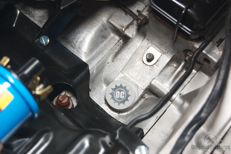
|
|
|
|
| rwilner |
Oct 2 2011, 06:40 PM
Post
#25
|
|
No Ghosts in the Machine Group: Members Posts: 953 Joined: 30-March 10 From: Boston, MA Member No.: 11,530 Region Association: North East States |
QUOTE(McMark @ Oct 2 2011, 08:14 PM)  Can't wait! Mark -- i found this link talking about how to wire up the innovate G5 gauge, looks straightforward |
|
|
|
| rwilner |
Oct 2 2011, 08:00 PM
Post
#26
|
|
No Ghosts in the Machine Group: Members Posts: 953 Joined: 30-March 10 From: Boston, MA Member No.: 11,530 Region Association: North East States |
Some progress this weekend.
I got the ignition coils mounted and the rest of the wiring harness installed. Here's what the ignition coils look like installed on Mark's custom brackets: (IMG:https://lh4.googleusercontent.com/-nuMTQYANwPw/TokSDbrtj1I/AAAAAAAAATA/Xk7Y94g22kY/s800/111001_3.JPG) Here's a closeup of the coil install, notice where the ground pickup is -- right on the bracket: (IMG:https://lh5.googleusercontent.com/-zDiDFk8GYdM/TokSJbOKPgI/AAAAAAAAATI/ROlTehnJMhU/s800/111001_4.JPG) (IMG:https://lh5.googleusercontent.com/-fVCAHivrfzg/TokSLIITthI/AAAAAAAAATM/UDmokJtS9Mc/s800/111001_5.JPG) Here's the wiring harness all dressed in. I also replaced all the engine tin and fan shroud screws (and in many cases, installed screws that were missing altogether) with stainless socket head cap screws. That blue paper towel in the distributor cavity will soon be replaced with a sweet OC plug! (IMG:https://lh3.googleusercontent.com/-1x89y4J6A4U/TokSL2B6TYI/AAAAAAAAATQ/7QB_b9hEDjw/s800/111001_6.JPG) I also mounted the MAP sensor and O2 sensor brain the factory location for the MPS. Per Mark's suggestion, to mount the O2 brain, I reformed a stainless P clamp to the profile of the O2 brain and lined the inside of the clamp with gasket material. My other idea was to get another air cleaner mount and attach it to the passenger side intake runners, and then mount the O2 brain to that. I like this better. (IMG:https://lh6.googleusercontent.com/-BR4IzijmoV4/TokSEOMMV3I/AAAAAAAAATE/qRr-n1Mv6z8/s800/111001_2.JPG) I noticed a small hole in the back of the MAP sensor. I thought this might have been the sensor's atmosphere reference (why else would there be a hole in the housing?), so I drilled a hole in the bracket to provide access -- check out the second hole from the right: (IMG:https://lh3.googleusercontent.com/-jdXrY7On6H8/TokSBeHwmeI/AAAAAAAAAS8/mxGPYx_RtrM/s800/111001_1.JPG) I'm also modifying the ash tray to become an iphone mount. Made some progress on that today also: (IMG:https://lh4.googleusercontent.com/-yWyLZTcKWUQ/TokSQ5qfrvI/AAAAAAAAATU/xjWPVqr9nVQ/s800/111001_7.JPG) (IMG:https://lh3.googleusercontent.com/-RA5FQNcCuRk/TokSRmyvAkI/AAAAAAAAATY/-fVW4Oxgdfc/s800/111001_8.JPG) I also got the interior disassembled to prepare for the gauge install, and designed my new gauge panel face. The small hole is for a toggle switch that turns my audio amplifier on and off: (IMG:https://lh3.googleusercontent.com/-BLTTAa0PGH4/TokVu7DOvhI/AAAAAAAAATk/Q-IaHUmdM48/s800/gauge%2520panel.png) That's it for now. Tomorrow I'm stopping by youdoit electronics on my way home to get what I need to make up my new gauge wiring harness. |
|
|
|
| moparrob |
Oct 2 2011, 08:49 PM
Post
#27
|
|
Senior Member Group: Members Posts: 646 Joined: 27-April 10 From: Los Angeles Member No.: 11,663 Region Association: None |
QUOTE(sean_v8_914 @ Sep 28 2011, 08:32 AM) Sean, that is nice. What is it though? |
|
|
|
| Mike Bellis |
Oct 2 2011, 08:57 PM
Post
#28
|
|
Resident Electrician Group: Members Posts: 8,345 Joined: 22-June 09 From: Midlothian TX Member No.: 10,496 Region Association: None |
Very nice! You will enjoy it.
|
|
|
|
| 76-914 |
Oct 2 2011, 09:35 PM
Post
#29
|
|
Repeat Offender & Resident Subaru Antagonist Group: Members Posts: 13,495 Joined: 23-January 09 From: Temecula, CA Member No.: 9,964 Region Association: Southern California |
Rich, is the top as viewed or is the panel upside down? That 1/2" border isn't enough to clear the top bracket/brace.
|
|
|
|
| 914_teener |
Oct 2 2011, 11:54 PM
Post
#30
|
|
914 Guru Group: Members Posts: 5,197 Joined: 31-August 08 From: So. Cal Member No.: 9,489 Region Association: Southern California |
What AFR gauge did you buy...and where are you going to mount it?
Thanks for this....and cool little distributor block off Mark. |
|
|
|
| rwilner |
Oct 3 2011, 05:13 AM
Post
#31
|
|
No Ghosts in the Machine Group: Members Posts: 953 Joined: 30-March 10 From: Boston, MA Member No.: 11,530 Region Association: North East States |
QUOTE(76-914 @ Oct 2 2011, 11:35 PM) Rich, is the top as viewed or is the panel upside down? That 1/2" border isn't enough to clear the top bracket/brace. It may be tough to see in the pic, but that is a 1.5" border around the top. |
|
|
|
| type47 |
Oct 3 2011, 05:31 AM
Post
#32
|
|
Viermeister Group: Members Posts: 4,254 Joined: 7-August 03 From: Vienna, VA Member No.: 994 Region Association: MidAtlantic Region |
Don't forget that gasket/grommet for the oil pressure hose where it goes through the tin...
I think it's 021.119.957 oil pressure boot. I found it at busdepot.com but NLA on pelican. |
|
|
|
| rwilner |
Oct 3 2011, 06:12 AM
Post
#33
|
|
No Ghosts in the Machine Group: Members Posts: 953 Joined: 30-March 10 From: Boston, MA Member No.: 11,530 Region Association: North East States |
QUOTE(type47 @ Oct 3 2011, 07:31 AM) Don't forget that gasket/grommet for the oil pressure hose where it goes through the tin... I think it's 021.119.957 oil pressure boot. I found it at busdepot.com but NLA on pelican. Found it Thanks Jim!! (IMG:style_emoticons/default/thumb3d.gif) |
|
|
|
| r_towle |
Oct 5 2011, 12:41 PM
Post
#34
|
|
Custom Member Group: Members Posts: 24,574 Joined: 9-January 03 From: Taxachusetts Member No.: 124 Region Association: North East States |
|
|
|
|
| rwilner |
Oct 5 2011, 12:47 PM
Post
#35
|
|
No Ghosts in the Machine Group: Members Posts: 953 Joined: 30-March 10 From: Boston, MA Member No.: 11,530 Region Association: North East States |
QUOTE(r_towle @ Oct 5 2011, 02:41 PM) Ha. I did do some work this week, I had to build my own wiring harness for the new gauge cluster. I have a buddy making up the face out of 1/8" stainless...a long story, he owed me a favor and that's what he had. I also installed the new temp sender. Let's hope that weird combo of seals in the taco plate holds oil! New harnesses are on the way from Jeff Bowlsby for my alternator and ignition. With Mark's new FI harness, I could't put the 40 y/o tired ones back in the car in good conscience. Will post some pics tonight |
|
|
|
| rwilner |
Oct 10 2011, 09:29 PM
Post
#36
|
|
No Ghosts in the Machine Group: Members Posts: 953 Joined: 30-March 10 From: Boston, MA Member No.: 11,530 Region Association: North East States |
Progress!
Got the interior pulled apart to get the new wires run for the gauges and iphone integration. (IMG:https://lh3.googleusercontent.com/-qCpUkxuuUr4/TpOoD45QVsI/AAAAAAAAAT8/7xunL0tDx6Q/s800/111004_2.JPG) I mocked up the gauge panel in cardboard to build the wiring harness while the panel is being fabbed at the metal shop. I test-fit the gauges with the amplifier installed in the center console -- it just fit! I'd rather be lucky than smart... (IMG:https://lh4.googleusercontent.com/-7vkQTGAcv68/TpOoRZ47IDI/AAAAAAAAAUs/Yx0X3oXdvws/s800/111008_7.JPG) (IMG:https://lh4.googleusercontent.com/-0ch0hIhZT1w/TpOoQijmudI/AAAAAAAAAUk/EbXPYATUTck/s800/111008_9.JPG) phew!! (IMG:https://lh5.googleusercontent.com/-hJUVgkUaCU0/TpOoPTeYyhI/AAAAAAAAAUc/12jxU58W4b8/s800/111008_8.JPG) I installed a new grounding point, then ran the new wires for the oil pressure gauge, AFR gauge, and serial communications to the microsquirt. Then the center console went back in. (IMG:https://lh6.googleusercontent.com/-NOIdj2M8svM/TpOoXtSokHI/AAAAAAAAAU0/U8ez2LD-MUQ/s800/111010_1.JPG) (IMG:https://lh4.googleusercontent.com/-VRg4rvy_snE/TpOoZDW8F3I/AAAAAAAAAU8/hPG7yMlThaI/s800/111010_2.JPG) (IMG:https://lh4.googleusercontent.com/-_vuK-HJgw7E/TpOoZiRK2zI/AAAAAAAAAVE/UZYAZiUpN2s/s800/111010_3.JPG) I also replaced my ignition harness and alternator harness with Bowlsby ones, plus i replaced my starter-to-battery cable with a new one. I had the 4 gauge cable lying around and the old one looked crusty. old and new ignition harness (IMG:https://lh5.googleusercontent.com/-d8VdNRhlp6U/TpOoJ8xGqAI/AAAAAAAAAUU/neKq7iLdOoc/s800/111008_4.JPG) old and new alternator harness (IMG:https://lh5.googleusercontent.com/-OGFtqcVgioc/TpOoJ0CWGNI/AAAAAAAAAUI/NEdRuAXua68/s800/111008_5.JPG) new starter cable (IMG:https://lh3.googleusercontent.com/-NxfOkuWfuuo/TpOoAsNx35I/AAAAAAAAATw/HBQ5hXlp4To/s800/111008_1.JPG) new cabling attached to the starter (IMG:https://lh6.googleusercontent.com/-pMx_gqDopbI/TpOodbQtmCI/AAAAAAAAAVM/9lMw43G7ltU/s800/111010_4.JPG) When I took the alternator off to install the harness, I noticed my boot was a shadow of its former self (IMG:style_emoticons/default/sad.gif). Fortunately Mark Heard had one in good shape to send me (IMG:style_emoticons/default/biggrin.gif) (IMG:https://lh4.googleusercontent.com/-HfeK3b2lpwc/TpOoAVBTogI/AAAAAAAAATs/jEs-DhUUdwU/s800/111008_2.JPG) That's it for now -- getting close to done! |
|
|
|
| 914werke |
Oct 10 2011, 09:33 PM
Post
#37
|
|
"I got blisters on me fingers" Group: Members Posts: 10,049 Joined: 22-March 03 From: USofA Member No.: 453 Region Association: Pacific Northwest |
Looks like you already had to mod the base plate on your console to fit the Rennshifter?
|
|
|
|
| rwilner |
Oct 10 2011, 09:35 PM
Post
#38
|
|
No Ghosts in the Machine Group: Members Posts: 953 Joined: 30-March 10 From: Boston, MA Member No.: 11,530 Region Association: North East States |
QUOTE(rdauenhauer @ Oct 10 2011, 11:33 PM) Look like you already had to mod the base plate on your console to fit the Rennshifter? Yep, I had to make it a little bit larger. |
|
|
|
| McMark |
Oct 10 2011, 09:39 PM
Post
#39
|
|
914 Freak! Group: Retired Admin Posts: 20,179 Joined: 13-March 03 From: Grand Rapids, MI Member No.: 419 Region Association: None |
Just thought of something, check the coil ground, as installed, by using an ohm meter between the showing portion of the ring connector and the case. Just to be on the safe side.
|
|
|
|
| rwilner |
Oct 10 2011, 09:42 PM
Post
#40
|
|
No Ghosts in the Machine Group: Members Posts: 953 Joined: 30-March 10 From: Boston, MA Member No.: 11,530 Region Association: North East States |
QUOTE(McMark @ Oct 10 2011, 11:39 PM) Just thought of something, check the coil ground, as installed, by using an ohm meter between the showing portion of the ring connector and the case. Just to be on the safe side. I will do tomorrow and report back |
|
|
|
|
1 User(s) are reading this topic (1 Guests and 0 Anonymous Users)
0 Members:

|
Lo-Fi Version | Time is now: 7th May 2024 - 07:42 PM |
Invision Power Board
v9.1.4 © 2024 IPS, Inc.