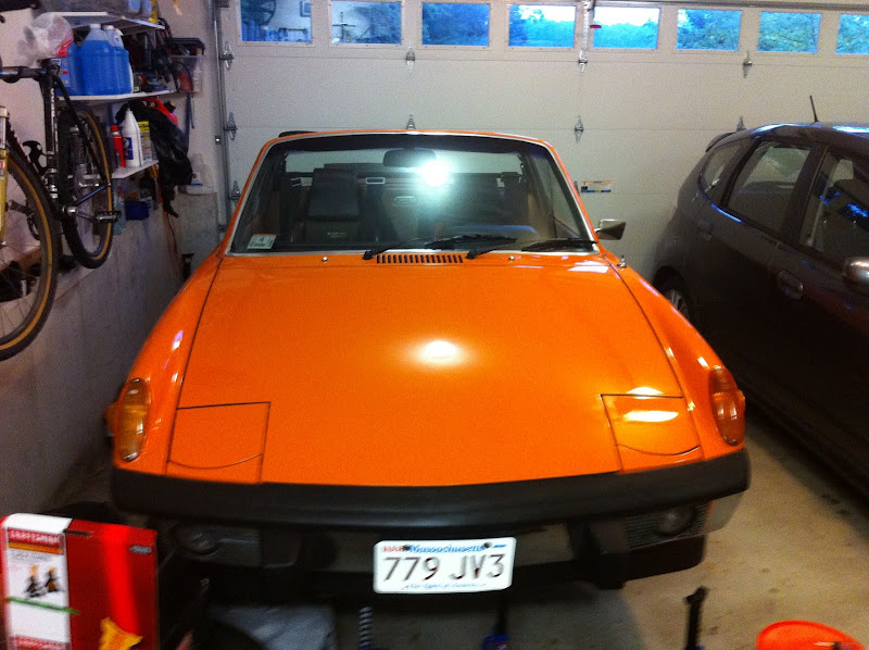
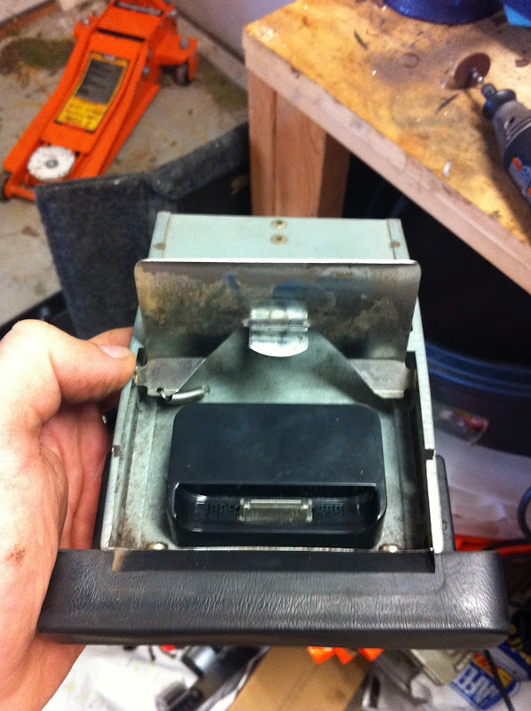
I'm converting my basically stock 2.0L (stock cam, euro Ps and Cs) over to microsquirt. Microsquirt is a megasquirt-derived fuel injection computer that's robot-soldered and factory encased in a weatherproof enclosure. The I/O is implemented as a single, 35-position weatherproof connector. The whole thing is about the size of 2 decks of cards.
The system I'm installing was engineered and supplied 100% by McMark. My understanding is that he usually provides these systems for motors that he builds, but I talked him into providing one for me. Below, I will document the install details here for anyone else who talks McMark into selling them a system, or who attempts something similar someday.
DISCLAIMER: I won't provide model numbers, prices, or any other info like that in this thread -- please contact McMark directly for those types of details. All I can say is that you get what you pay for and this is a top-notch system that will work for the remaining life of the car.
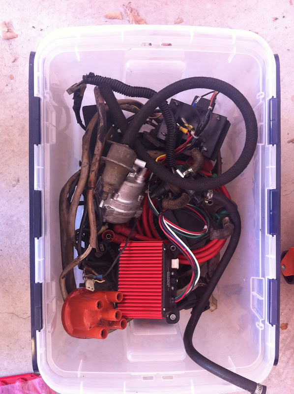
The system provides the following components new:
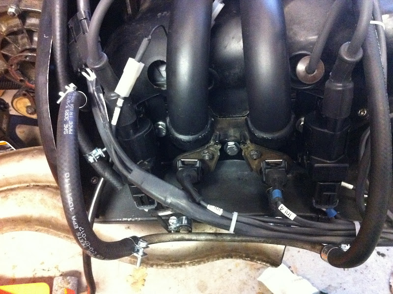
- 4 new injectors
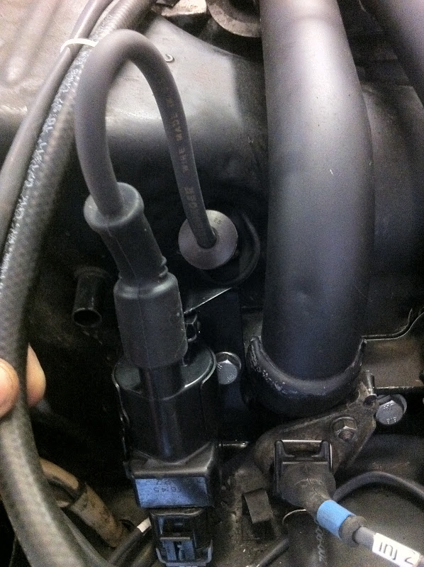
- 4 new ignition coils
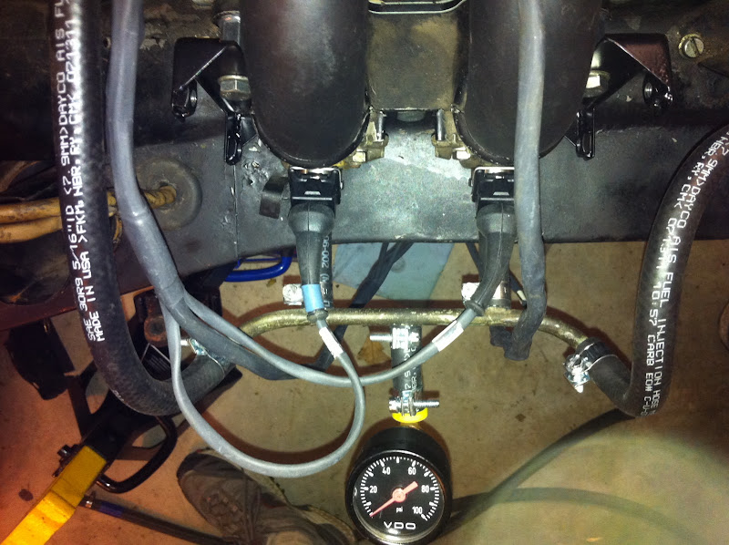
- a MAP sensor
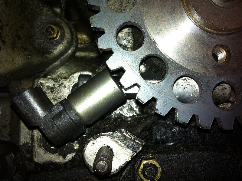
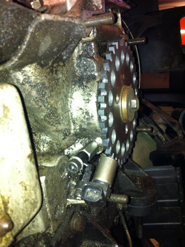
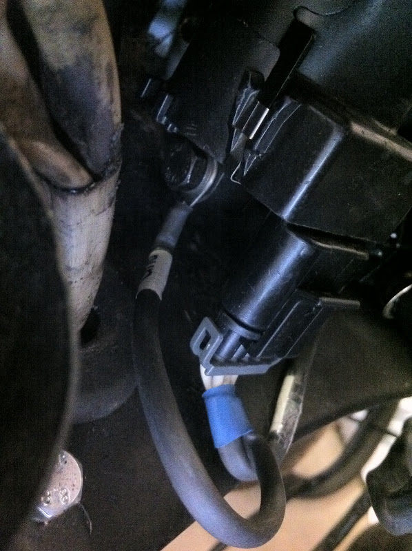
- a crank postion sensor (CPS)
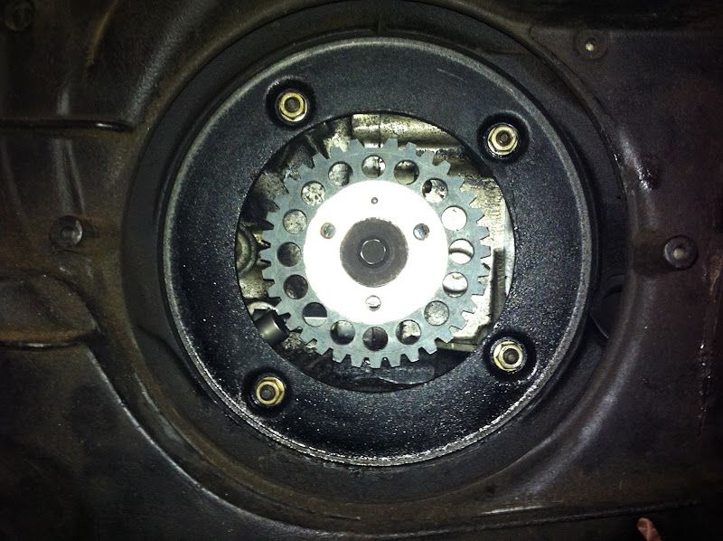
- a crank position trigger wheel
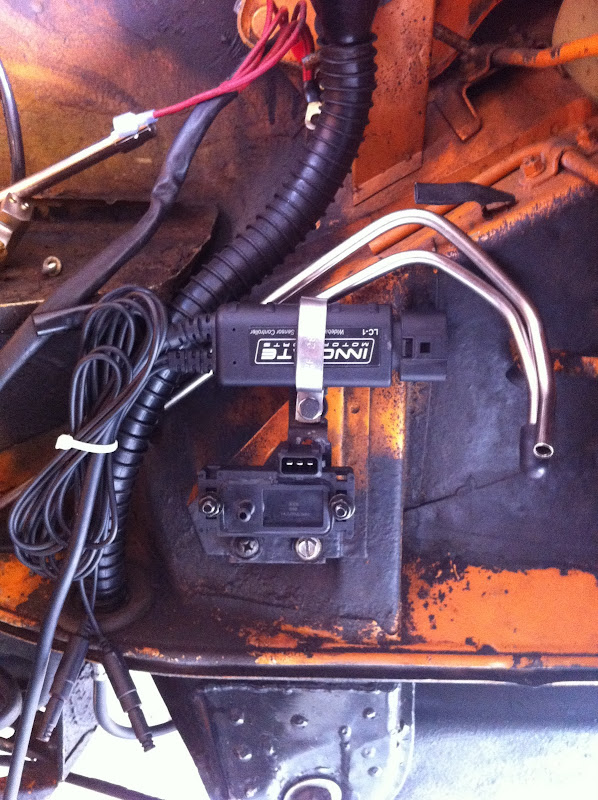
- an oxygen sensor and brain
- a throttle position sensor
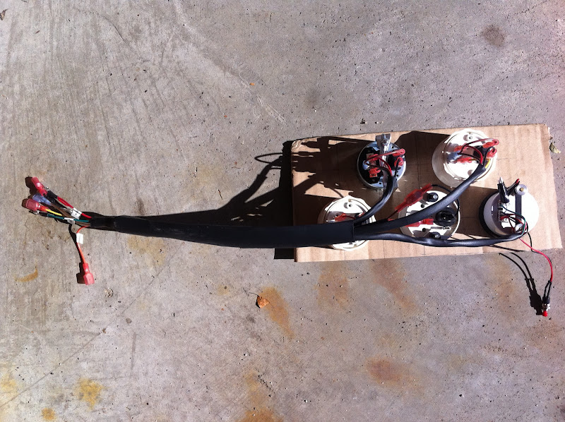
- a new custom wiring harness
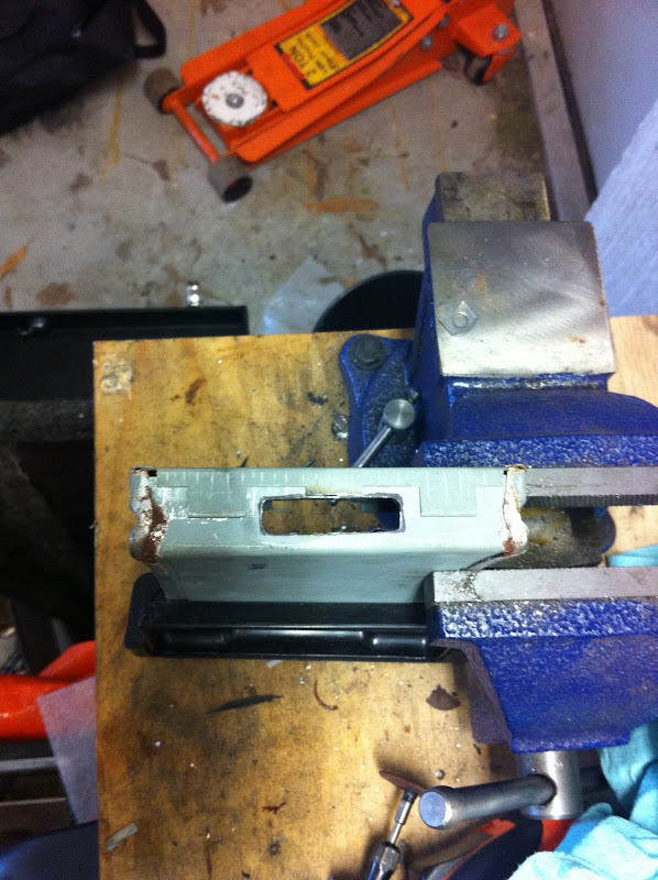
- miscellaneous mounting brackets, blank-off plates, plugs, fuse blocks, etc.
- intake air temp sensor
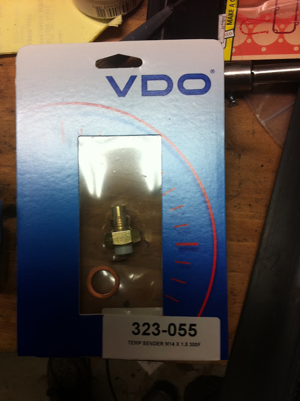
- cyl head temp sensor
- MPS
- decel valve
- cold start valve
- AAR
- thermotime switch
- distributor
- main FI wiring harness
- fuel injectors
- a pile of vacuum hoses
- As we all know, the stock FI computer controls only fuel, and spark is controlled with mechanical and vacuum advance at the distributor. The MS computer controls both fuel and spark which allows me to optimize both power and fuel economy under all load conditions.
- This is a closed-loop system, meaning it adjusts fuel and spark in real-time based on the lambda/AFR in the exhaust.
- This system uses brand new, modern components with a brand new wiring harness.
- This system will scale up to larger motors easily -- just tune a new fuel map, same sensors, same wiring harness.
- I get to plug my laptop into my 40-year-old car, which I think is cool.
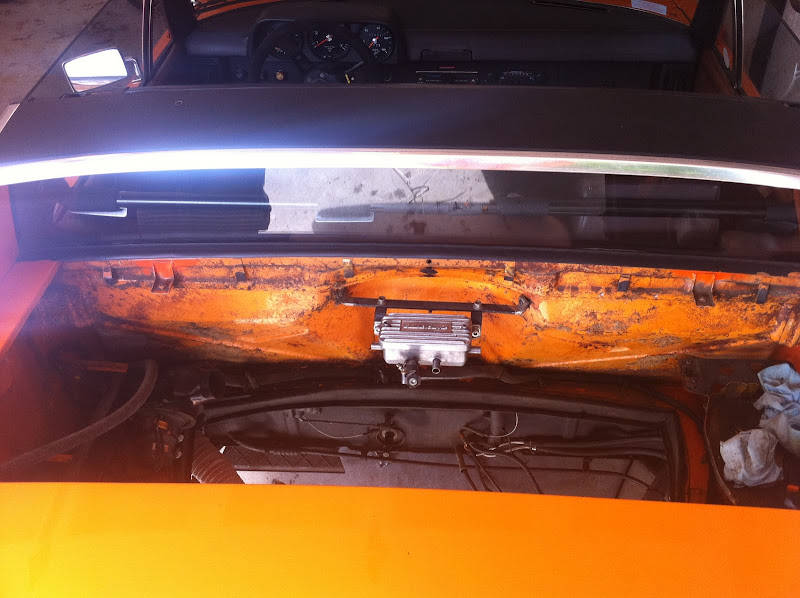
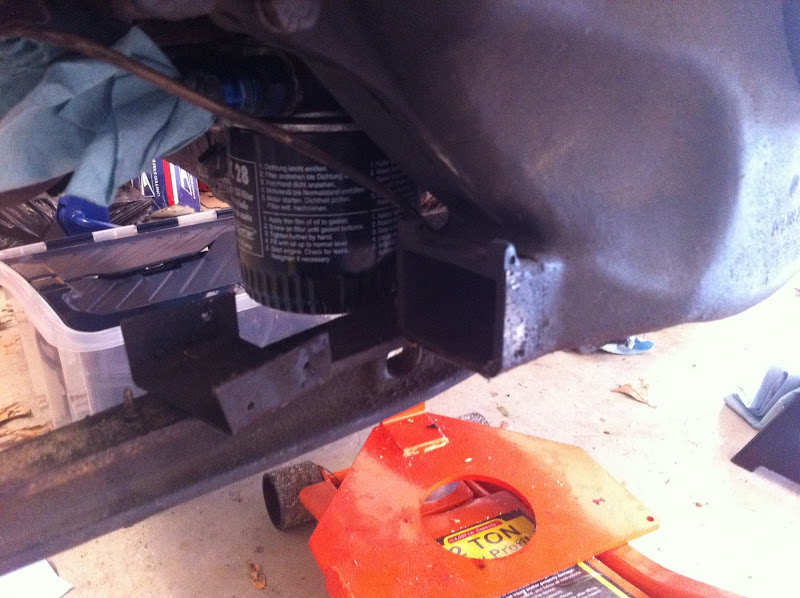
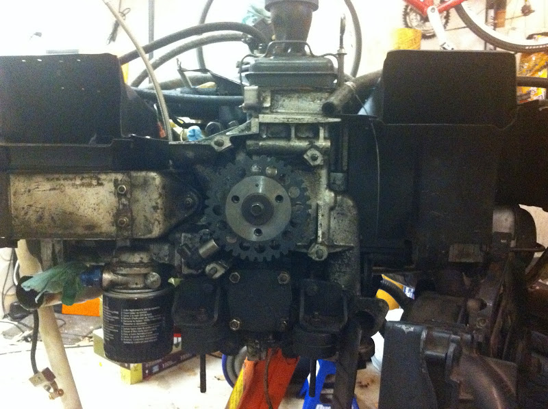
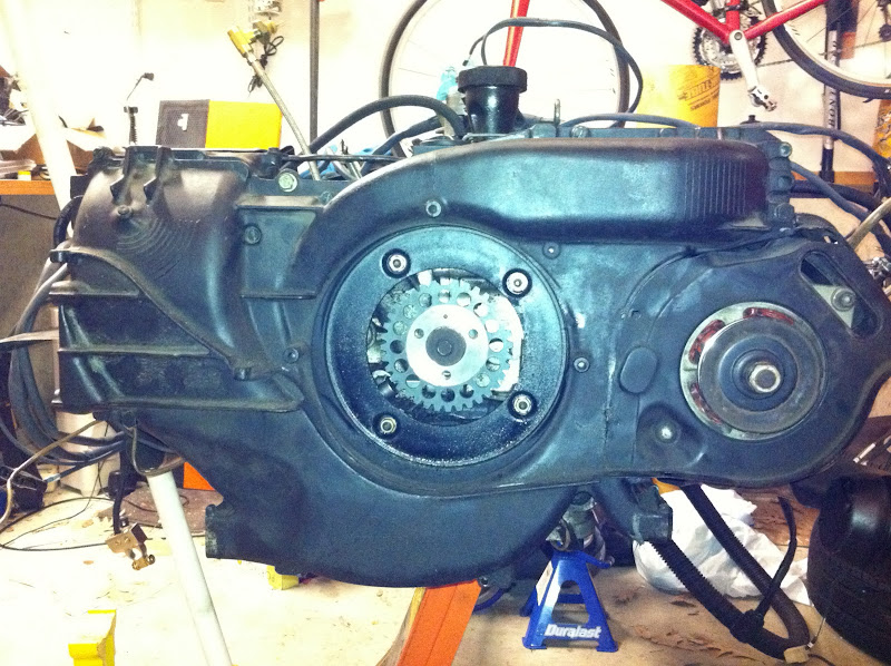
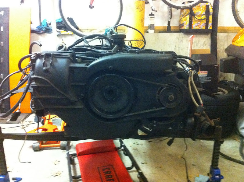
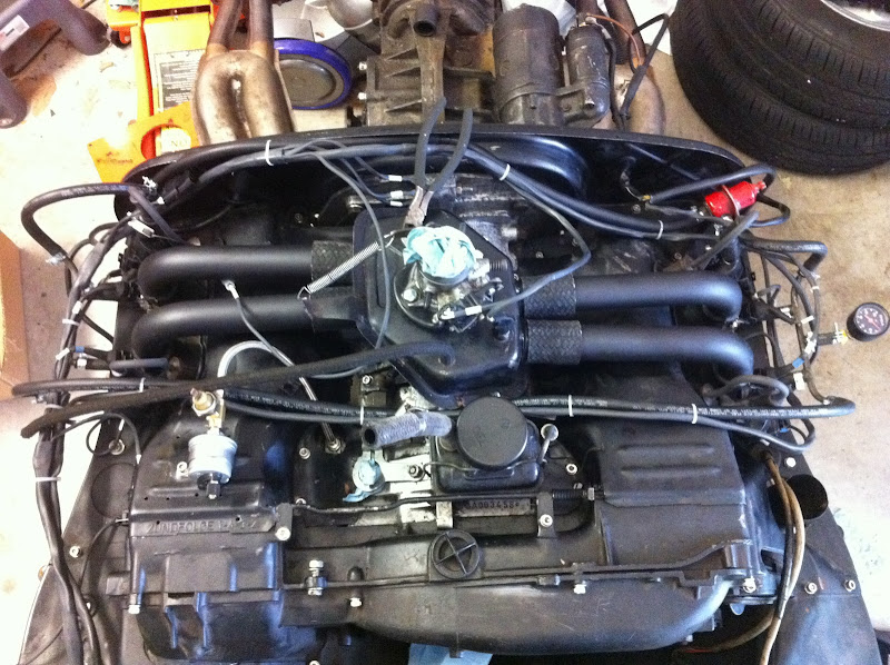
- Drop engine
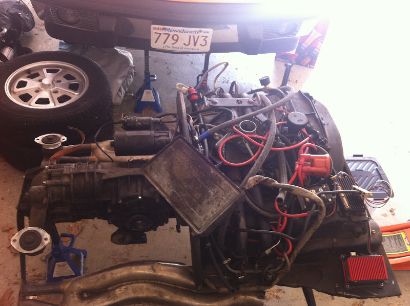
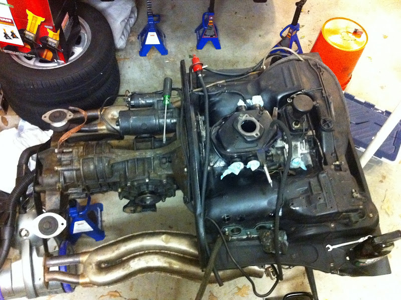
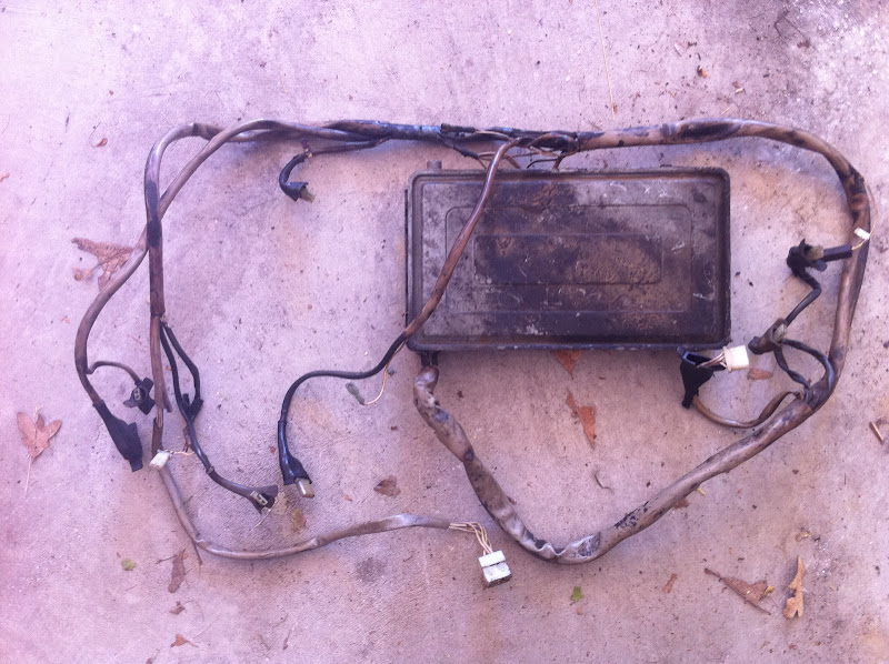
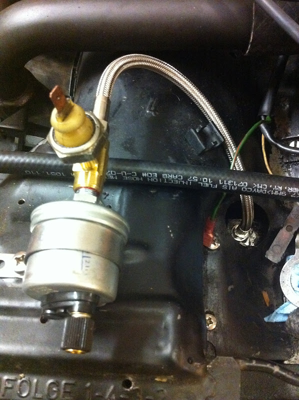
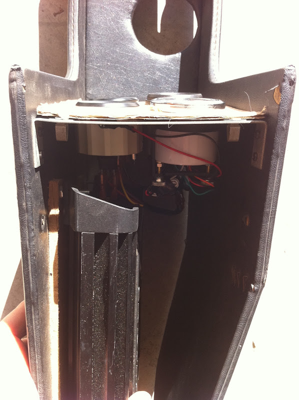
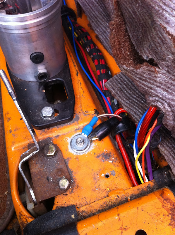
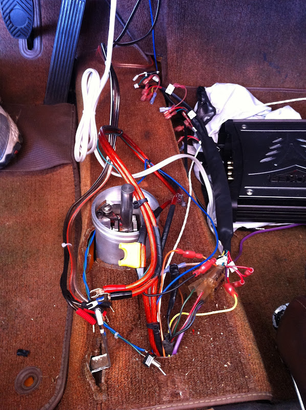
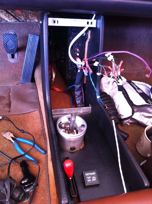
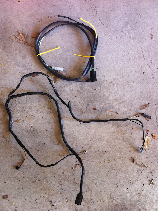
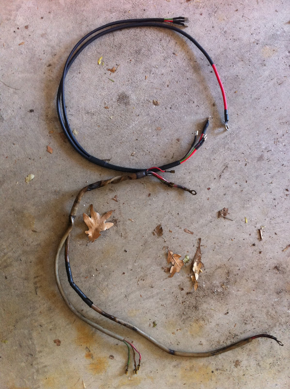
- Remove all the old FI stuff
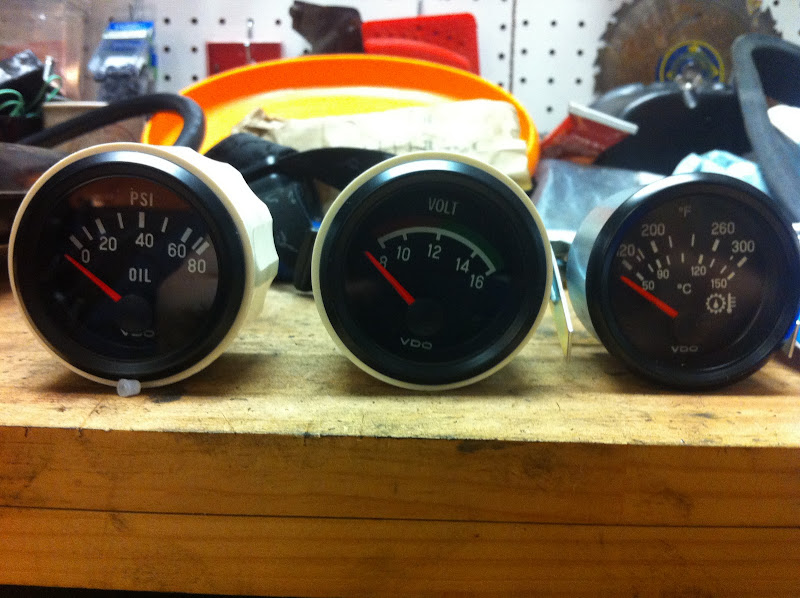
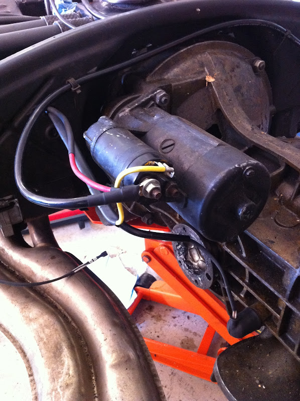
- Install new FI stuff
- Reinstall engine
- rough tune on the street
- fine tune on the dyno
- drive it a lot
OK, enough babbling, on to the install!


 I think McMark will get alot of orders for this, I'll be gettin' in the line, I know...

 McFuelInjection is going to really catch on... Are you going to go with my distributor replacement idea? Or are you going to stay stealth and have your distributor in place?


![popcorn[1].gif](http://www.914world.com/bbs2/style_emoticons/default/popcorn[1].gif)


 . Fortunately Mark Heard had one in good shape to send me