Help - Search - Members - Calendar
Full Version: My Microsquirt Conversion
914World.com > The 914 Forums > 914World Garage
Pages: 1, 2, 3
rwilner
I got my engine back in the car. Some questions for the experts:

1) there's a gap between the engine tin and the new seals I installed. Did I install the seals upside down?

2) If so, can I remove, flip, and reinstall the seals with the engine in the car or do I have to remove the engine again to do this?

See pics...

IPB Image

IPB Image
McMark
The seal should hang down, and there should be a small upturned section. That upturn hooks under the tin. Try that... wink.gif
rwilner
QUOTE(McMark @ Oct 23 2011, 12:34 AM) *

The seal should hang down, and there should be a small upturned section. That upturn hooks under the tin. Try that... wink.gif


i love doing things twice!

looks like the engine is coming out and in again today...

beer3.gif
rwilner
Had a fairly productive weekend.

I received Tom's raised fuse block and installed it. It's a raised 4 position fuse block that protects the 4 hot wires connecting to the battery. Installation was a snap while the engine was out, although installing with the engine in place wouldn't be very difficult either.

IPB Image

IPB Image

After I cleaned up a bunch of gunk I found my GA engine number! Also, check out this SWEET plug McMark supplied to clean up the distributor channel. Style and function!

IPB Image

IPB Image

My engine impeller was missing 1 fin, so I purchased this very nice one from Mark Heard and popped it in place. Mark also gave me an alternator cooling boot in great shape, which replaced the liquefied one shown earlier in this thread.

IPB Image

IPB Image

IPB Image

IPB Image

I installed a new engine soundpad from AppBiz (highly recommended) and new engine bay seals from Mikey914. I recommend that unlike me, you do not install the engine seals upside down the first time around... smile.gif

IPB Image

I drilled a hole in the engine tin to run the wires for the O2 brain. I had to determ and reterm the weatherpack connector to feed the wire through the hole, which was a no-brainer. The O2 brain will mount to one of the transmission mounts. I had to relocate the brain because the O2 sensor wire was not long enough and no extension was available or recommended by the manufacturer. I also built a little harness to calibrate the O2 sensor, which is required every 10k miles or once per year.

IPB Image

IPB Image

Now it was time to lure a buddy to my house with a six pack and put the engine back in the car.

IPB Image

Not quite ready to fire the engine, but with some effort this week I should get there by the weekend -- just reconnecting stuff now!
radmelon
Rich- where did you place the O2 sensor bung? Did you weld it into the exhaust manifold (F tube) or further down after the heat exchanger? Great pictures by the way. Very helpful!
rwilner
QUOTE(radmelon @ Nov 13 2011, 12:33 PM) *

Rich- where did you place the O2 sensor bung? Did you weld it into the exhaust manifold (F tube) or further down after the heat exchanger? Great pictures by the way. Very helpful!


hey rad...

welcome.png (or at least, welcome to posting)

I placed the O2 bung at the "collector" portion of my bursch muffler, right before the muffler portion. Here are some pics:

IPB Image

I coated the weld and bung in hi temp paint to inhibit the rust some:

IPB Image

The guy who welded in the bung is named Maurizio. His shop is within walking distance from my house and he always has a bunch of cool old cars parked in and around his shop. Whenever the sun is shining he drives this sweet 356! drooley.gif

IPB Image


Over the last 2 weeks, Mark and I have been working on refining the wiring harness some and getting the settings in the microsquirt controller just right. So finally, this weekend, Rich Towle came over and we got the car started! piratenanner.gif

In Mark's words, I'm now in "tuning land" and hope to be driving.gif by next weekend!

For any future purchasers of Mark's FI kit -- after I get the microsquirt settings dialed in, I will post the MSQ (settings file) in this thread so you can download it, load it up, turn the key and be 75% of the way to a tuned car.
914_teener
popcorn[1].gif

Thanks for the update. I was wondering what happened to this install and thread.
rwilner
More Progress...

I pulled a plug after my initial tuning efforts. Think it was running a bit rich?!

IPB Image

So I began to investigate and found several issues.

Issue 1: My intake air temp sensor was reading as 0 degrees F. This is an obvious cause of rich running.
The MS calculates fuel delivery using a volumetric efficiency (VE) table, where the amount of fuel injected is calculated based on the mass of air being sucked in via the intake. If I had a mass airflow sensor, that would be measured directly. Instead of a MAF sensor, I am using a MAP (pressure) sensor and the intake air temp sensor. The MS uses these two sensors and calculates the air mass using the ideal gas law. Well, 0 deg F air is wicked dense which means lots of fuel.

It was just dumping fuel into the combustion chamber.

I fixed this by RTFM and discovering the MS has an internal biasing resistance of 2490 ohms. I also characterized my IAT sensor in boiling water, freezing water, and at room temp. The results are shown in the attached screenshot:

IPB Image

Issue 2: The CHT was reading as 0 degrees F. The stock CHT grounds against the engine block (like a spark plug). The MS has the sensor ground separated from the dirty engine block ground. Well, that resulted in the CHT reading as an open circuit, since the resistance of the CHT had no ground reference. I was left with 3 options:
  1. Tie the sensor ground to the engine ground. This was workable but not ideal because it would introduce noise into all the sensor inputs (TPS, MAP, IAT, CHT, O2). How much noise? Who knows, but if it can be avoided...
  2. Find an NTC thermistor with an M10 thread. I think they sell these at the same place you can buy unicorns.
  3. Drill out a stock CHT and mount (epoxy) a 2-wire NTC thermistor in that body, essentially turning the stock CHT into a thermowell. The epoxy is thermally conductive but not electrically conductive. This was the best solution.
Mark fabbed up option 3, check out the attached pics. NTC thermistors are COTS that can be purchased inexpensively at places like digikey and mouser.

IPB Image

IPB Image

This should arrive today or tomorrow. I will characterize this sensor the same as the IAT, program it in and we should be in business.

I also had to program the LC1 (oxygen sensor brain) to scale properly.

Lesson learned: make sure every sensor is reading correctly and accurately before you even turn the key to start tuning. Seems obvious, but in the complication of getting the engine started, sometimes the obvious can be overlooked.

I have saturday afternoon (55 deg and sunny) reserved for getting this thing on the road and driving, we'll see if I can make it happen!
ConeDodger
Rich, I'm watching this with great interest. Marks's EFI system using the Microsquirt ECU is actually a little 'smarter' than SDS. Mine works, but it could be more accurate and tunable. smile.gif
draganc
Great work/job!!

And I'm gald you haven't lost your humor:

"...Find an NTC thermistor with an M10 thread. I think they sell these at the same place you can buy unicorns..."
zymurgist
cheer.gif cheer.gif cheer.gif

I nominate this thread for "classic" status.
rwilner
QUOTE(zymurgist @ Nov 18 2011, 10:19 AM) *

cheer.gif cheer.gif cheer.gif

I nominate this thread for "classic" status.


thanks...maybe we should wait until I'm on the road and driving...

It's really fun to learn about fuel injection. There is so much happening just to inject the right amount of fuel and spark at the right time.

Also -- Mark has been really fun and enjoyable to work with. If I'm lucky, he's only doing 2 other things when I call him with a question...usually it's more like 4 or 5 smile.gif

The ultimate goal of this effort is to have a modern, turn-key, bolt-on replacement solution for the factory FI system. It's just one more option for us to keep our cars on the road and running great.

I'm really close now!
rwilner
QUOTE(ConeDodger @ Nov 18 2011, 10:06 AM) *

Rich, I'm watching this with great interest. Marks's EFI system using the Microsquirt ECU is actually a little 'smarter' than SDS. Mine works, but it could be more accurate and tunable. smile.gif


Hey Rob
MS is definitely more tunable, but it's also more complicated. There is the classic tradeoff.

Is the extra tunability worth the extra complication? That's the big question, and unless you're trying to squeeze every ounce of power and efficiency out of the engine, it might not make a huge difference. If you're happy with your car's performance (and it certainly sounds like you are), then SDS was the right choice for you.

I chose MS because it's what Mark engineered his system around and it required zero fabrication and modification of the engine bay / body / stock wiring. Also, the laptop-style tuning interface with realtime displays and datalogging really appeal to the way I think and understand systems like this.

A perfect example: the trigger wheel wasn't reading RPM initially. Because the MS is so flexible, I was able to load diagnostic firmware onto the controller and discover the root cause of the problem. Because the MS is so complicated, it turned out that software configuration was the root cause of the problem smile.gif

Like carbs vs. FI or 4 vs. 6 or X vs Y, there is never (or rarely) a right answer...only a best answer depending on your goals, skills, and expectations.

By the way -- your ITB setup looks awesome and it's great to see PEFI on a high performance big 4. When I build my big 4, I am considering moving to ITBs.

type47
Updates? popcorn[1].gif
ChrisFoley
QUOTE(type47 @ Feb 5 2012, 10:08 AM) *

Updates? popcorn[1].gif

The day after Rich got the EFI operating correctly, a couple weeks ago, his wife had their first baby.
rwilner
QUOTE(Racer Chris @ Feb 5 2012, 10:38 AM) *

The day after Rich got the EFI operating correctly, a couple weeks ago, his wife had their first baby.


As Chris said...

Jeffrey Linus Wilner born 1/25 @ 4:32 pm. Everyone's happy and healthy. He has a really strong grip already...maybe strong enough for a torque wrench? He here is passed out after I gave him a lecture on port injection vs. direct injection:

IPB Image

Back to our regularly scheduled programming!

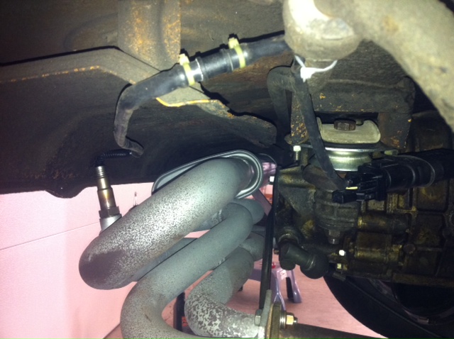
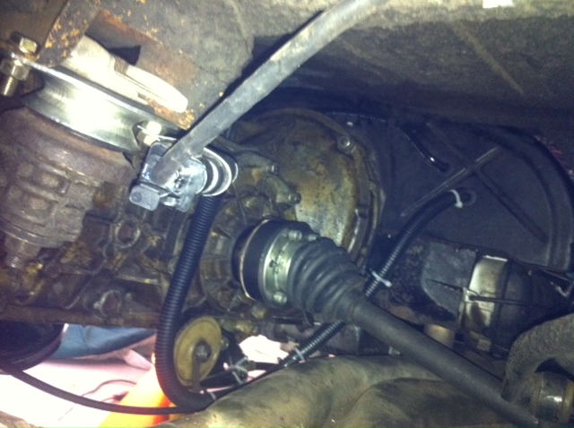
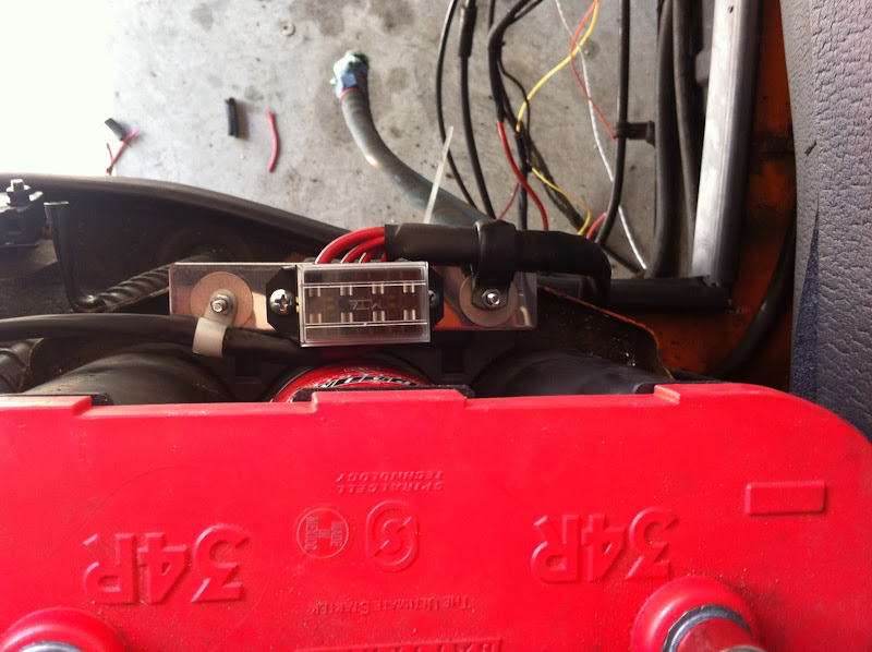
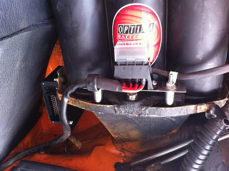
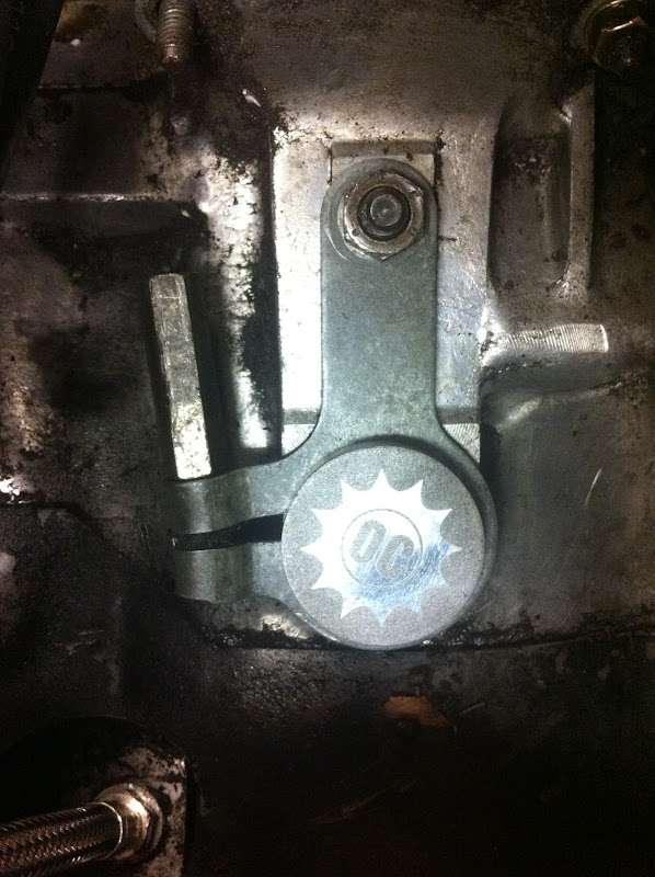
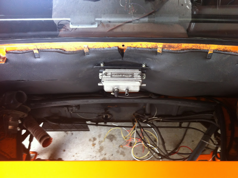
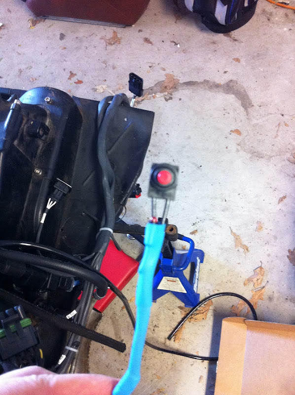
Here's a picture of the oxygen sensor and oxygen sensor brain mounting. The brain --> ECU cable is routed down to the clutch cable wheel plate -- it looks like it's touching the heat exchanger in the photo, but it clears just fine. The brain is secured to one of the transmission mount bolts using a reformed P clamp. I used a longer bolt in this location to receive the second nut.
IPB Image

IPB Image

I am very happy to report that the car is running 100% on all 4 cylinders -- I'm using it now for (seemingly daily) diaper runs. For a long time I was having an issue where the car was running great on cylinders 1 and 3, but ran like crap once I plugged in 2 and 4. Many hours of troubleshooting later, we discovered that there is a parameter in the software called "offset / advance for output #2" that I had set to 180 degrees...well...the system automatically advanced output #2 180 degrees based on the configuration (4 cyl / even fire / wasted spark), so I was actually advancing the second output 360 degrees by setting that parameter to 180. Not good. After I set that parameter to 0, the car ran like a champ.

Tonight I'll post up my .msq file so that any others planning a mega/microsquirt conversion can use it as a starting point. Anyone purchasing McMark's setup should be able to use this as a turn-key file to get their car started, running, and driving. You will definitely have to make tuning adjustments for your motor no matter what you're running, although if you have a stock GA 2.0L, this file should be 80% or better to a final tune.

Note: I developed this tuning file using the V2 microsquirt enclosure. DIYEFI is now selling the V3 enclosure which has a slightly different pinout and form factor; however, I have tested this file with the V3 enclosure and it works great. I'd actually recommend the V2 enclosure over the V3 if you can find one because the V2 enclosure is extruded aluminum and the V3 is molded plastic.

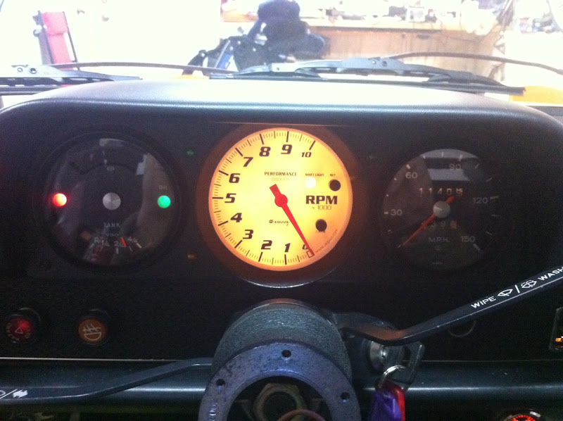
I still have some final bugs to work out (tach not working with the MS output, O2 reading is a bit wacky, oil temp gauge not reading, need to replace ignition switch), but the car starts right up and drives awesome. beer3.gif

Please feel free to post any questions about this setup in this thread.
914werke
Good head of hair on the boy, Congrtats!
rwilner
Slowly working out my issues as time allows...

My mom and dad were in town, so while my mom was on baby duty, my dad and I got some work done on the car.

I replaced the sealed beam tungsten lenses with the H4 kit from pelican and also replaced the ignition switch. But the bigger win was getting a working tach.

There is definitely a way to get the microsquirt to work with the stock tach. But, time is at a premium with me these days so experimenting with a charge-pump circuit is not in the cards.

I selected an aftermarket tach based on a suggestion from another member here -- an equus 8080. PRetty short money from summit ($110 I think.) This is the same company that makes the special timing light that works correctly with my new wasted spark DIS. It is also the only aftermarket tach I've found that has an inductive spark plug pickup option! Very cool. Turns out I didn't need that because this thing picked up the signal from the microsquirt Tach output like a champ.

I relocated the turn signal (green LEDs) and hi beam (amber LED) indicators to the gauge bezel. Also shot the gauge bezel with a fresh coat of enamel.

IPB Image

Only remaining issues are my oil temp gauge and O2 sensor readings. I keep forgetting to post the .msq...
bohalrantipol
Man this is good info! thanks for putting this up! I am in the process of assembling a system very similar to yours. Please do put up the .msq!

Thanks again!

Please note all of the exclamations!!!
falconfp2001
QUOTE(rwilner @ Feb 23 2012, 07:51 AM) *

Slowly working out my issues as time allows...

My mom and dad were in town, so while my mom was on baby duty, my dad and I got some work done on the car.

I replaced the sealed beam tungsten lenses with the H4 kit from pelican and also replaced the ignition switch. But the bigger win was getting a working tach.

There is definitely a way to get the microsquirt to work with the stock tach. But, time is at a premium with me these days so experimenting with a charge-pump circuit is not in the cards.

I selected an aftermarket tach based on a suggestion from another member here -- an equus 8080. PRetty short money from summit ($110 I think.) This is the same company that makes the special timing light that works correctly with my new wasted spark DIS. It is also the only aftermarket tach I've found that has an inductive spark plug pickup option! Very cool. Turns out I didn't need that because this thing picked up the signal from the microsquirt Tach output like a champ.

I relocated the turn signal (green LEDs) and hi beam (amber LED) indicators to the gauge bezel. Also shot the gauge bezel with a fresh coat of enamel.

IPB Image

Only remaining issues are my oil temp gauge and O2 sensor readings. I keep forgetting to post the .msq...


Where are you getting the tack signal for your gauge? I can't find the output from the DB37 for a tack signal but they say that you can take it from the (-) pole of the coil packs and then run it through a converter to reduce the signal by half to use it with the stock gauge.
rwilner
QUOTE(falconfp2001 @ Mar 6 2012, 03:41 PM) *

Where are you getting the tack signal for your gauge? I can't find the output from the DB37 for a tack signal but they say that you can take it from the (-) pole of the coil packs and then run it through a converter to reduce the signal by half to use it with the stock gauge.


The microsquirt has a 35 pin ampseal connector, not a DB37 connector. Perhaps you're using a megasquirt?

Regardless -- I am driving the tachometer from pin 35 -- "tach output." Check out this wiring diagram.

If you're running wasted spark like I am, you'll probably read twice actual the rpm if you connect the (-) coil to the stock tachometer. You'll have to build an interface circuit of some kind.

If you're running sequential spark, you might get away with connecting one of the coil pack (-) wires to the stock tachometer.
r_towle
nice....

I am somewhat available this weekend and next...
Its warm smile.gif

Dunno if you want to come up here and see what we can do..
We can now get it up in the air.

I am off to NYC till fri, but will be here over the weekend...tinkering.

rich
falconfp2001
QUOTE(rwilner @ Mar 6 2012, 01:02 PM) *

QUOTE(falconfp2001 @ Mar 6 2012, 03:41 PM) *

Where are you getting the tack signal for your gauge? I can't find the output from the DB37 for a tack signal but they say that you can take it from the (-) pole of the coil packs and then run it through a converter to reduce the signal by half to use it with the stock gauge.


The microsquirt has a 35 pin ampseal connector, not a DB37 connector. Perhaps you're using a megasquirt?

Regardless -- I am driving the tachometer from pin 35 -- "tach output." Check out this wiring diagram.

If you're running wasted spark like I am, you'll probably read twice actual the rpm if you connect the (-) coil to the stock tachometer. You'll have to build an interface circuit of some kind.

If you're running sequential spark, you might get away with connecting one of the coil pack (-) wires to the stock tachometer.


I found this online and it should work for the tach

http://www.autosportlabs.com/tach-adapter-p-65.html
rwilner
A small update:

I have replaced the innovate O2 setup with an AEM analog unit (part number 30-5130). Here's why:

The innovate O2 unit requires a connection to a single ground reference. This ground must be the engine block since the high-current sensor heater uses this ground. As stated previously, the microsquirt separates the sensor ground from the signal ground -- the O2 sensor input on the microsquirt is referencing the signal ground.

IOW: The microsquirt O2 signal input references the signal ground. The Innovate O2 signal feed is tied to engine ground. To get the microsquirt to read O2, I'd have to tie the signal ground to the engine ground...not a good practice.

Well, the *analog* AEM unit has an isolated signal ground for the feed to an engine management system. This is pretty much the only unit I found that has this feature...even the digital equivalent made by the same company doesn't have this feature!

A few other things I discovered about microsquirt and tuning:
  • The bootloader serial ground is tied to SIGNAL ground inside the microsquirt box. I'm using this ground to ground out my cyl head temp sensor and the O2 sensor.
  • The microsquirt O2 sampling algorithm is tied to RPM! This means that you will NOT get any O2 readings unless the engine is running, so putting the key in ACC and expecting the MS O2 reading to match your dash gauge will not work. If you want to test your O2 wiring, you can take out your fuel pump relay and crank the engine -- this will get you RPM readings without starting the engine. Running a poorly tuned engine for a length of time (very rich in particular) can damage the O2 sensor, so best make sure your primary tuning aid, the O2 sensor, is reading correctly before you run the car.
  • Tuning without an O2 sensor and an accurate CHT sensor is dangerous -- see this recent thread.
I'll post some pics of the new gauge and wiring. My plan is to use the autotune feature of TS to set my VE tables...based on the MS forums, this seems to be a simple and reliable way of getting a 90% dialed-in fuel map (assuming you have a good target AFR table).
falconfp2001
QUOTE(rwilner @ Mar 28 2012, 07:06 AM) *

A small update:

I have replaced the innovate O2 setup with an AEM analog unit (part number 30-5130). Here's why:

The innovate O2 unit requires a connection to a single ground reference. This ground must be the engine block since the high-current sensor heater uses this ground. As stated previously, the microsquirt separates the sensor ground from the signal ground -- the O2 sensor input on the microsquirt is referencing the signal ground.

IOW: The microsquirt O2 signal input references the signal ground. The Innovate O2 signal feed is tied to engine ground. To get the microsquirt to read O2, I'd have to tie the signal ground to the engine ground...not a good practice.

Well, the *analog* AEM unit has an isolated signal ground for the feed to an engine management system. This is pretty much the only unit I found that has this feature...even the digital equivalent made by the same company doesn't have this feature!

A few other things I discovered about microsquirt and tuning:
  • The bootloader serial ground is tied to SIGNAL ground inside the microsquirt box. I'm using this ground to ground out my cyl head temp sensor and the O2 sensor.
  • The microsquirt O2 sampling algorithm is tied to RPM! This means that you will NOT get any O2 readings unless the engine is running, so putting the key in ACC and expecting the MS O2 reading to match your dash gauge will not work. If you want to test your O2 wiring, you can take out your fuel pump relay and crank the engine -- this will get you RPM readings without starting the engine. Running a poorly tuned engine for a length of time (very rich in particular) can damage the O2 sensor, so best make sure your primary tuning aid, the O2 sensor, is reading correctly before you run the car.
  • Tuning without an O2 sensor and an accurate CHT sensor is dangerous -- see this recent thread.
I'll post some pics of the new gauge and wiring. My plan is to use the autotune feature of TS to set my VE tables...based on the MS forums, this seems to be a simple and reliable way of getting a 90% dialed-in fuel map (assuming you have a good target AFR table).


How is the AEM controller? I think gonna switch as this Innovate MTX is not what I expected. It takes a while to heat up but it won't display anything until after I've driven 2 to 5 minutes. I could sit in the driveway all day and it shows 22.4 all day.
rwilner
QUOTE(falconfp2001 @ Apr 7 2012, 04:05 PM) *


How is the AEM controller? I think gonna switch as this Innovate MTX is not what I expected. It takes a while to heat up but it won't display anything until after I've driven 2 to 5 minutes. I could sit in the driveway all day and it shows 22.4 all day.


The AEM gauge / controller is working great for me. The gauge matches the MS reading, the system doesn't need calibration, and the sensor warms up in less than 30 seconds. I can recommend it.

I believe the Innovate should warm up in a similar amount of time...if it doesn't there could be an issue with the sensor or wiring.
rwilner
Just a small update...

My car now revs to the redline!

Before, the car would rev freely to 4k and bounce off of it like a rev limiter. Note that there is a software rev limiter in MS (which you can configure either as spark retard or fuel cut) but I had it disabled.

I then read this thread on the microsquirt forums. In the V1 and V2 microsquirts, there was an issue with the VR circuit such that a diode had to be changed and a capacitor (c30) removed. I did both of these...desoldering surface mount components is a real PITA...but I got it done and now the car revs freely to the redline and BEYOND! Anyone that purchases a new microsquirt will not have this issue as the new circuit board layouts have these fixes.

I'm now at the stage where I'm honing in on an optimal tune. In this recent thread I tuned my VE tables in response to AFR, but now that I can rev to redline, I can tune an area of the VE table that was previously inaccessible.

Once I am 100% happy with the tune I will post the msq as I've been promising to do for what seems like months.
mightyohm
Wow, nice job spotting that thread about the VR sensor input mod! I would have been banging my head against the wall for a while, before assuming there was a design problem with the VR circuit!

Mark and I had issues with the ignition coil input as well, so it sounds like the MS guys need to rework the entire ignition system in the next rev.

If you need to do any more SMT rework in the future, feel free to contact me. I do this stuff for a living and have all the equipment to make changes without damaging the board. (I'm the one who modified your Microsquirt coil driver outputs.)

rwilner
QUOTE(mightyohm @ Apr 10 2012, 10:30 AM) *

Wow, nice job spotting that thread about the VR sensor input mod! I would have been banging my head against the wall for a while, before assuming there was a design problem with the VR circuit!

Mark and I had issues with the ignition coil input as well, so it sounds like the MS guys need to rework the entire ignition system in the next rev.

If you need to do any more SMT rework in the future, feel free to contact me. I do this stuff for a living and have all the equipment to make changes without damaging the board. (I'm the one who modified your Microsquirt coil driver outputs.)


Hey Jeff,
I started the troubleshooting by measuring the VR signal output AC rms voltage at high rpm with the thought that there was an issue there...at 3500 rpm it's over 100V! I knew I might be exceeding a reverse breakdown voltage for a transistor or diode at that point, so I went digging and found that thread.

I'm still not sure why removing C30 was required...it looks like it's just adjusting phase to me...but I don't have the circuit schematics electronically and I don't have PSPICE so I just took a shot based on guidance in the thread and it worked.

The V3 MS is a reworked layout with some adjusted component values. The new software version (3.77) also has better filtering of inputs as well. I suspect the ignition coil issues may now be eliminated.

Nice job on the mods to the board and nice touch with the conformal coat BTW...I need to touch it up now wink.gif

Rich
rwilner
I just discovered a cool new feature of the MicroSquirt!

The latest code revision allows you to toggle between 2 different sets of tuning parameters (VE fuel maps and AFR targets) at the flip of a switch. This means you can set one tune for 87 and another for 93, or one tune for pump gas and another for race gas.

I might have to mess with this a bit later... idea.gif
r_towle
messing, no driving....
At least its fun...

Rich
falconfp2001
QUOTE(rwilner @ Apr 10 2012, 11:27 AM) *

I just discovered a cool new feature of the MicroSquirt!

The latest code revision allows you to toggle between 2 different sets of tuning parameters (VE fuel maps and AFR targets) at the flip of a switch. This means you can set one tune for 87 and another for 93, or one tune for pump gas and another for race gas.

I might have to mess with this a bit later... idea.gif


I think they mentioned that as a new feature. You can use one of the spare inputs for a switch. hehehe

If you didn't see my last post for the Expanded CLT Temps. I fugured out how to load MS2Extra and it works. Gives you a lot of options that the regular firmware does not have. I don't know if it works with MicroSquirt but you can always e-mail DIYAutoTune about it.
falconfp2001
QUOTE(rwilner @ Apr 10 2012, 11:27 AM) *

I just discovered a cool new feature of the MicroSquirt!

The latest code revision allows you to toggle between 2 different sets of tuning parameters (VE fuel maps and AFR targets) at the flip of a switch. This means you can set one tune for 87 and another for 93, or one tune for pump gas and another for race gas.

I might have to mess with this a bit later... idea.gif


Also the Latest MS Extra code lets you make the tables switch either by software or a hardware switch. Hardware requires some pretty tricky soldering directly to the board. Who's the guy that did you mods?
rwilner
QUOTE(falconfp2001 @ Apr 11 2012, 01:06 AM) *

Also the Latest MS Extra code lets you make the tables switch either by software or a hardware switch. Hardware requires some pretty tricky soldering directly to the board. Who's the guy that did you mods?


Jeff Keyzer, mightyohm on this site. In the microsquirt, the flexfuel signal is accessible in the ampseal connector so there's no board soldering required...not sure about megasquirt proper.
falconfp2001
QUOTE(rwilner @ Apr 11 2012, 05:35 AM) *

QUOTE(falconfp2001 @ Apr 11 2012, 01:06 AM) *

Also the Latest MS Extra code lets you make the tables switch either by software or a hardware switch. Hardware requires some pretty tricky soldering directly to the board. Who's the guy that did you mods?


Jeff Keyzer, mightyohm on this site. In the microsquirt, the flexfuel signal is accessible in the ampseal connector so there's no board soldering required...not sure about megasquirt proper.


The MS Extra is loadable to MicroSquirt. When you run the .bat file to load, it will ask what type of ECU you are using, mega or Micro.
rwilner
Over 1000 miles on this system now...I'm very pleased with how it's performing.

Attached is my .msq file. It should work with both megasquirt and microsquirt. If any of you use it and have questions, feel free to PM me.

(Of course -- use at your own risk.)

Click to view attachment
rwilner
QUOTE(rwilner @ Jun 17 2012, 07:31 AM) *

Over 1000 miles on this system now...I'm very pleased with how it's performing.

Attached is my .msq file. It should work with both megasquirt and microsquirt. If any of you use it and have questions, feel free to PM me.

(Of course -- use at your own risk.)

Click to view attachment


Trying the zip file one more time since the last one didn't post correctly.
rwilner
QUOTE(rwilner @ Aug 14 2012, 09:32 PM) *

QUOTE(rwilner @ Jun 17 2012, 07:31 AM) *

Over 1000 miles on this system now...I'm very pleased with how it's performing.

Attached is my .msq file. It should work with both megasquirt and microsquirt. If any of you use it and have questions, feel free to PM me.

(Of course -- use at your own risk.)

Click to view attachment


Trying the zip file one more time since the last one didn't post correctly.


Hm, still empty

I emailed sirandy to see if there's any way to post this file to the thread, in the meantime if you want the file, PM me.
JmuRiz
Very cool status updates (see, no one needs facebook!)
I wish microsquirt could individually control 6-cyl...the packaging is so nice. I'll just keep telling myself that's the reason I don't have EFI on my 2.7 engine and my old Benz CIS motor.
SirAndy
QUOTE(rwilner @ Aug 14 2012, 06:35 PM) *
I emailed sirandy to see if there's any way to post this file to the thread, in the meantime if you want the file, PM me.


Ok, try this link:
http://www.914world.com/cantnamethisdownlo..._RTW_914_2L.zip

idea.gif
gothspeed
Awesome thread smilie_pokal.gif !!! ..... how is this car running now? .... sunglasses.gif
r_towle
He sold it back to the original owner and bought a 911.
gothspeed
QUOTE(r_towle @ Jan 19 2014, 07:22 AM) *

He sold it back to the original owner and bought a 911.

Why would anyone buy a 911 ? ........ screwy.gif

I guess everyone needs to make their own mistakes ..... popcorn[1].gif
r_towle
QUOTE(gothspeed @ Jan 19 2014, 03:48 PM) *

QUOTE(r_towle @ Jan 19 2014, 07:22 AM) *

He sold it back to the original owner and bought a 911.

Why would anyone buy a 911 ? ........ screwy.gif

I guess everyone needs to make their own mistakes ..... popcorn[1].gif

Hey now...
I have a 911 also....

gothspeed
QUOTE(r_towle @ Jan 19 2014, 12:58 PM) *

QUOTE(gothspeed @ Jan 19 2014, 03:48 PM) *

QUOTE(r_towle @ Jan 19 2014, 07:22 AM) *

He sold it back to the original owner and bought a 911.

Why would anyone buy a 911 ? ........ screwy.gif

I guess everyone needs to make their own mistakes ..... popcorn[1].gif

Hey now...
I have a 911 also....

yeah, I had a few ..... back when I did not know any better ..... biggrin.gif
rwilner
QUOTE(gothspeed @ Jan 19 2014, 05:02 PM) *

QUOTE(r_towle @ Jan 19 2014, 12:58 PM) *

QUOTE(gothspeed @ Jan 19 2014, 03:48 PM) *

QUOTE(r_towle @ Jan 19 2014, 07:22 AM) *

He sold it back to the original owner and bought a 911.

Why would anyone buy a 911 ? ........ screwy.gif

I guess everyone needs to make their own mistakes ..... popcorn[1].gif

Hey now...
I have a 911 also....

yeah, I had a few ..... back when I did not know any better ..... biggrin.gif


I now have the space to buy another car. Not "Towle barn" space, but enough...

Passively looking for a 914 again smile.gif

This time, I think I'll actually combine this with a 2056 or a 2270.
r_towle
I got one for you...
76, green with white interior...
Near me, not mine...new paint and interior.

Not started in ten years...
You can borrow my truck and trailer.

Rich
2mAn
QUOTE(r_towle @ Jun 28 2016, 08:05 PM) *

I got one for you...

Rich


enabler! happy11.gif

If I get the car Im looking for I plan to do the same and this is a 2270
rwilner
QUOTE(r_towle @ Jun 28 2016, 11:05 PM) *

I got one for you...
76, green with white interior...
Near me, not mine...new paint and interior.

Not started in ten years...
You can borrow my truck and trailer.

Rich


I'm interested, at the right price of course.

BBBs and white interior have to go.
mailmanboise
Ive got a 73 with a 1.7 ish motor, I believe its had some jug work done because they have paint pen marks on them. The paperwork I have says that it has a Norris 272 cam. Im running a proper D jet system ( she had twin 40's). Ive had to slighty modify the MPS, at idle Ive got a fluctuations in vacuum as well as low static compression (85 psi on all 4) she has a nice "lop" to her as she idle and it strong all the way thru the power curve. I can chase down my friends 76 914 2.0 going up a hill..
Im interested in doing a microsquirt system, with either a map or maf sensor, I guessing because of the fluctuation of vacuum at idle I may have to go with an MAF sensor. Any advice would be appreciated
RobClick to view attachment
This is a "lo-fi" version of our main content. To view the full version with more information, formatting and images, please click here.
Invision Power Board © 2001-2024 Invision Power Services, Inc.