|
|
|
Porsche, and the Porsche crest are registered trademarks of Dr. Ing. h.c. F. Porsche AG.
This site is not affiliated with Porsche in any way. Its only purpose is to provide an online forum for car enthusiasts. All other trademarks are property of their respective owners. |
|
|

  |

| yeahmag |
 Feb 2 2012, 12:49 AM Feb 2 2012, 12:49 AM
Post
#1
|
|
Advanced Member  Group: Members Posts: 2,421 Joined: 18-April 05 From: Pasadena, CA Member No.: 3,946 Region Association: Southern California |
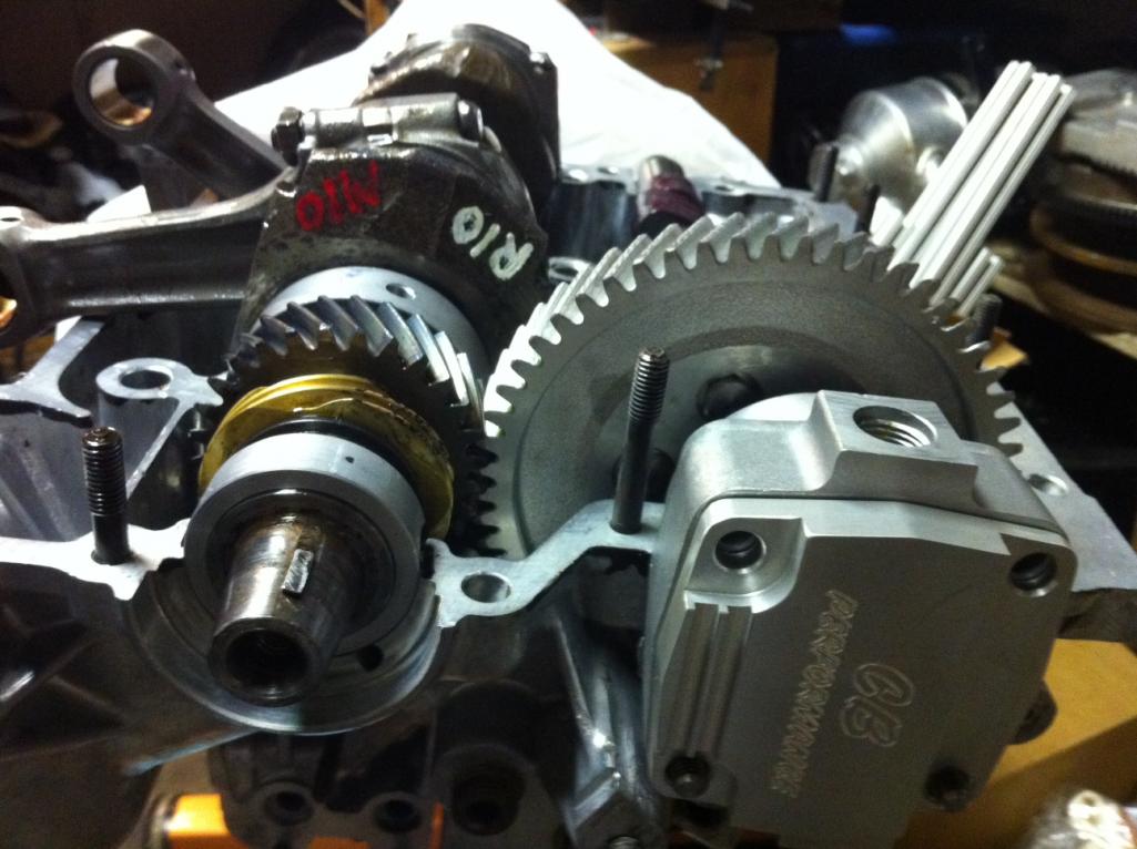
Installed crank, gears, cam, and rods. Dry fit CB's dry sump pump and modified the tang and clearanced drive tang boss.
 |
   |

 
|
| EdwardBlume |
Feb 2 2012, 01:01 AM
Post
#2
|
|
914 Wizard Group: Members Posts: 12,338 Joined: 2-January 03 From: SLO Member No.: 81 Region Association: Central California |
QUOTE(yeahmag @ Feb 1 2012, 10:49 PM)  Installed crank, gears, cam, and rods. Dry fit CB's dry sump pump and modified the tang and clearanced drive tang boss. (IMG:style_emoticons/default/beer.gif) |
|
|
|
| ThePaintedMan |
Feb 2 2012, 06:43 AM
Post
#3
|
|
Advanced Member Group: Members Posts: 3,885 Joined: 6-September 11 From: St. Petersburg, FL Member No.: 13,527 Region Association: South East States |
Cool! Wish I had the guts to attempt a rebuild. One day!
|
|
|
|
| jaxdream |
Feb 2 2012, 09:06 AM
Post
#4
|
|
Senior Member Group: Members Posts: 974 Joined: 8-July 08 From: North Central Tennessee Member No.: 9,270 Region Association: South East States |
Will the fan housing bolt up / clear the new pump ?? Or are using another cooling option ?? Looks good !!! (IMG:style_emoticons/default/piratenanner.gif)
Jack |
|
|
|
| mrbubblehead |
Feb 2 2012, 09:52 AM
Post
#5
|
|
Twodollardoug Group: Members Posts: 1,155 Joined: 17-December 10 From: calimesa ca. Member No.: 12,492 Region Association: Southern California |
what are you going to do about your engine mounts?
|
|
|
|
| yeahmag |
Feb 2 2012, 10:46 AM
Post
#6
|
|
Advanced Member Group: Members Posts: 2,421 Joined: 18-April 05 From: Pasadena, CA Member No.: 3,946 Region Association: Southern California |
I will need to modify the fan housing to clear the oil pump. I will also have to custom make some motor mounts.
|
|
|
|
| mrbubblehead |
Feb 2 2012, 03:55 PM
Post
#7
|
|
Twodollardoug Group: Members Posts: 1,155 Joined: 17-December 10 From: calimesa ca. Member No.: 12,492 Region Association: Southern California |
you are one step ahead of me. i am doing the same as you. same pump also.....
i just finished all my case mods, and concentrating on building my sump tank. did you hav to grind your cam bolts? do you remember how much you took off the snout of the pump? i am going to use tangerine racing's horizontal fan set up, so my engine mounts shouldnt be a problem. |
|
|
|
| yeahmag |
Feb 2 2012, 04:01 PM
Post
#8
|
|
Advanced Member Group: Members Posts: 2,421 Joined: 18-April 05 From: Pasadena, CA Member No.: 3,946 Region Association: Southern California |
I ground about 2mm off that pump. Maybe more. I also made the tang have some angle at the end like the stock tangs. I made the tang length match the one I got from Raby years ago. I took a bit off the boss holding the drive tang to make sure it was clear of the cam. I probably took off 1mm at most on the boss.
I did grind my cam bolts to be safe, but I probably didn't have to with the ones Jake sent me. What case mods did you do? |
|
|
|
| mrbubblehead |
Feb 2 2012, 04:16 PM
Post
#9
|
|
Twodollardoug Group: Members Posts: 1,155 Joined: 17-December 10 From: calimesa ca. Member No.: 12,492 Region Association: Southern California |
since im not using the stock oil cooler or stock oil filter i took them out of the circuit. i also welded up the relief holes and took both relief system out of the circuit also. (IMG:http://www.914world.com/bbs2/uploads_offsite/i722.photobucket.com-12492-1328220964.1.jpg)
|
|
|
|
| yeahmag |
Feb 2 2012, 04:19 PM
Post
#10
|
|
Advanced Member Group: Members Posts: 2,421 Joined: 18-April 05 From: Pasadena, CA Member No.: 3,946 Region Association: Southern California |
How are you routing the oil for the pressure stage? The galley from the pressure side of the pump goes right to the oil filter...
|
|
|
|
| mrbubblehead |
Feb 2 2012, 06:18 PM
Post
#11
|
|
Twodollardoug Group: Members Posts: 1,155 Joined: 17-December 10 From: calimesa ca. Member No.: 12,492 Region Association: Southern California |
i used this diagram (IMG:http://www.914world.com/bbs2/uploads_offsite/i722.photobucket.com-12492-1328228312.1.gif)
and modified it to this (IMG:http://www.914world.com/bbs2/uploads_offsite/i722.photobucket.com-12492-1328228669.1.gif) 1. jaycee 3 port remote oil filter/relief @ 80 psi 2. remote oil cooler 3. sump tank in my picture you can see i welded a fitting on the passage from the pump (where the old filter stand was) then it goes thru the remote filter, oil cooler, and then straight to the mains via the oil cooler location. another welded fitting. i just cut of the the old cooler stand off the case. |
|
|
|
| yeahmag |
Feb 2 2012, 09:41 PM
Post
#12
|
|
Advanced Member Group: Members Posts: 2,421 Joined: 18-April 05 From: Pasadena, CA Member No.: 3,946 Region Association: Southern California |
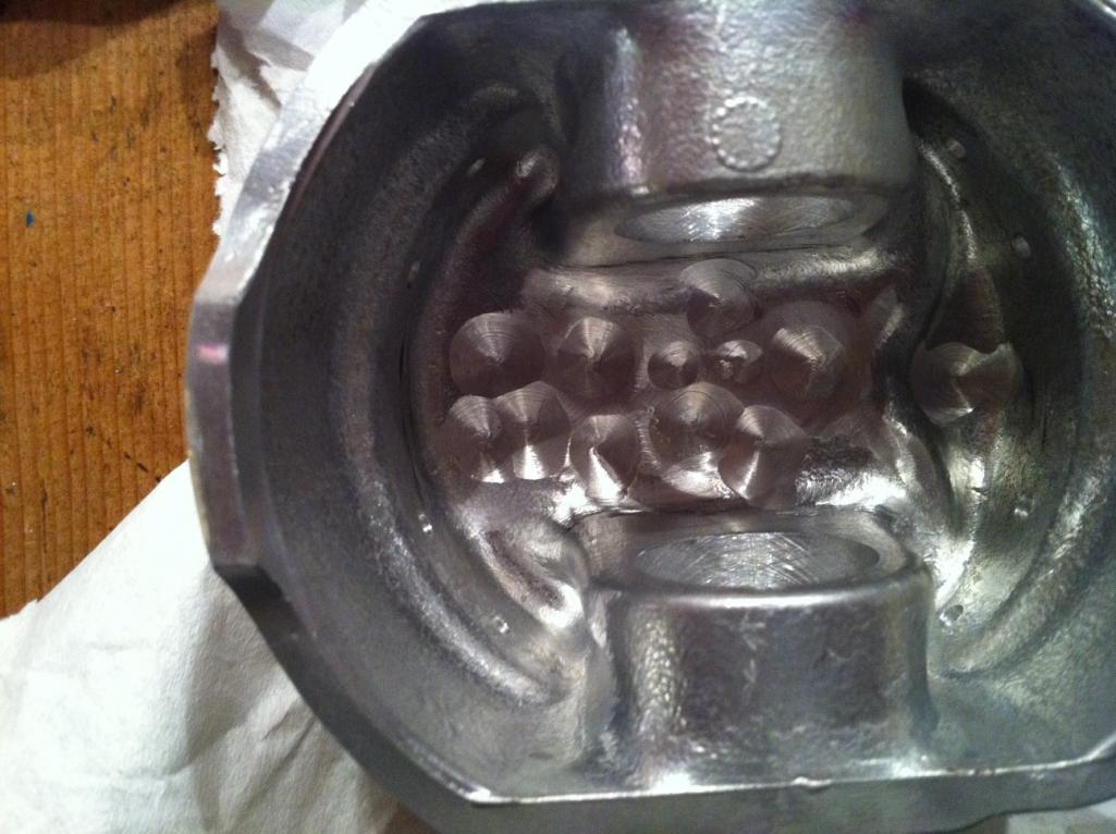
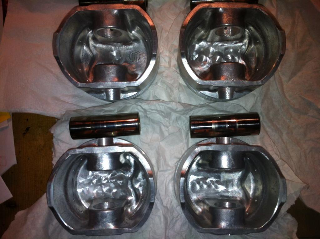
Here are pictures of the pistons after going through the ultrasonic cleaner and then me balancing them. I used a 1g scale, a 1/2" drill bit, and an air powered angle grinder with a small sanding disk (just to clean up any sharp edges). The all are at 570g now. They were as much a 3g out. Weights ranged from 570g to 573g.
  |
|
|
|
| Valy |
Feb 2 2012, 11:20 PM
Post
#13
|
|
Senior Member Group: Members Posts: 1,671 Joined: 6-April 10 From: Sunnyvale, CA Member No.: 11,573 Region Association: Northern California |
QUOTE(mrbubblehead @ Feb 2 2012, 04:18 PM) i used this diagram (IMG:http://www.914world.com/bbs2/uploads_offsite/i722.photobucket.com-12492-1328228312.1.gif) and modified it to this (IMG:http://www.914world.com/bbs2/uploads_offsite/i722.photobucket.com-12492-1328228669.1.gif) 1. jaycee 3 port remote oil filter/relief @ 80 psi 2. remote oil cooler 3. sump tank in my picture you can see i welded a fitting on the passage from the pump (where the old filter stand was) then it goes thru the remote filter, oil cooler, and then straight to the mains via the oil cooler location. another welded fitting. i just cut of the the old cooler stand off the case. So how do you pump oil out of the sump? |
|
|
|
| jmill |
Feb 3 2012, 07:07 PM
Post
#14
|
|
Green Hornet Group: Members Posts: 2,449 Joined: 9-May 08 From: Racine, Wisconsin Member No.: 9,038 Region Association: Upper MidWest |
(IMG:style_emoticons/default/agree.gif)
I was thinking the same thing. Somehow youi need to get the oil in the tank to the suction side of the pump. All the dry sump systems I've seen have a scavenge and a pressure pump. |
|
|
|
| mrbubblehead |
Feb 3 2012, 07:22 PM
Post
#15
|
|
Twodollardoug Group: Members Posts: 1,155 Joined: 17-December 10 From: calimesa ca. Member No.: 12,492 Region Association: Southern California |
QUOTE(jmill @ Feb 3 2012, 05:07 PM) (IMG:style_emoticons/default/agree.gif) I was thinking the same thing. Somehow youi need to get the oil in the tank to the suction side of the pump. All the dry sump systems I've seen have a scavenge and a pressure pump. i know, this diagram was just for me. i didnt draw them in because i know that the feed and return from the sump tank go to the oil pump. this diagram was to figure out how i was gonna get in and out of the case. |
|
|
|
| Woody |
Feb 3 2012, 07:48 PM
Post
#16
|
|
Sandbox Rabblerouser and head toilet scrubber Group: Members Posts: 3,858 Joined: 28-December 10 From: San Antonio Texas Member No.: 12,530 Region Association: Southwest Region |
You are going to love that engine. (IMG:style_emoticons/default/piratenanner.gif) (IMG:style_emoticons/default/beerchug.gif)
|
|
|
|
| mrbubblehead |
Feb 4 2012, 04:18 PM
Post
#17
|
|
Twodollardoug Group: Members Posts: 1,155 Joined: 17-December 10 From: calimesa ca. Member No.: 12,492 Region Association: Southern California |
any more progress yeahman? do you know what you are going to use for a sump tank yet?
|
|
|
|
| yeahmag |
Feb 14 2012, 11:32 AM
Post
#18
|
|
Advanced Member Group: Members Posts: 2,421 Joined: 18-April 05 From: Pasadena, CA Member No.: 3,946 Region Association: Southern California |
Been cleaning parts like mad. Finally ready to close the case up after checking the fit of the drive tang and boss on the CB dry sump pump.
I also got around to modifying the oil filter housing. I used a slide hammer with a small, blind bearing pull attachment and removed the bypass system. I then cut an AL slug to fit and MIG'ed it in. With regards to the tank, I'm using a very nice Patterson tank that Blake sold me. I'll be mounting it up front and trying to figure out how to mount an oil cooler up there too. |
|
|
|
| yeahmag |
May 24 2012, 12:22 PM
Post
#19
|
|
Advanced Member Group: Members Posts: 2,421 Joined: 18-April 05 From: Pasadena, CA Member No.: 3,946 Region Association: Southern California |
OK. The long block is together and I'm starting on the valve train geometry. Here are some pic's:
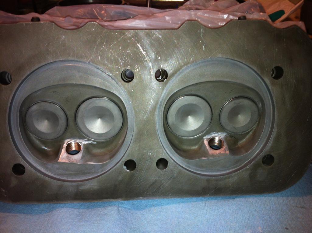 The head after using Ajax to lap the cylinders |
|
|
|
| yeahmag |
May 24 2012, 12:23 PM
Post
#20
|
|
Advanced Member Group: Members Posts: 2,421 Joined: 18-April 05 From: Pasadena, CA Member No.: 3,946 Region Association: Southern California |
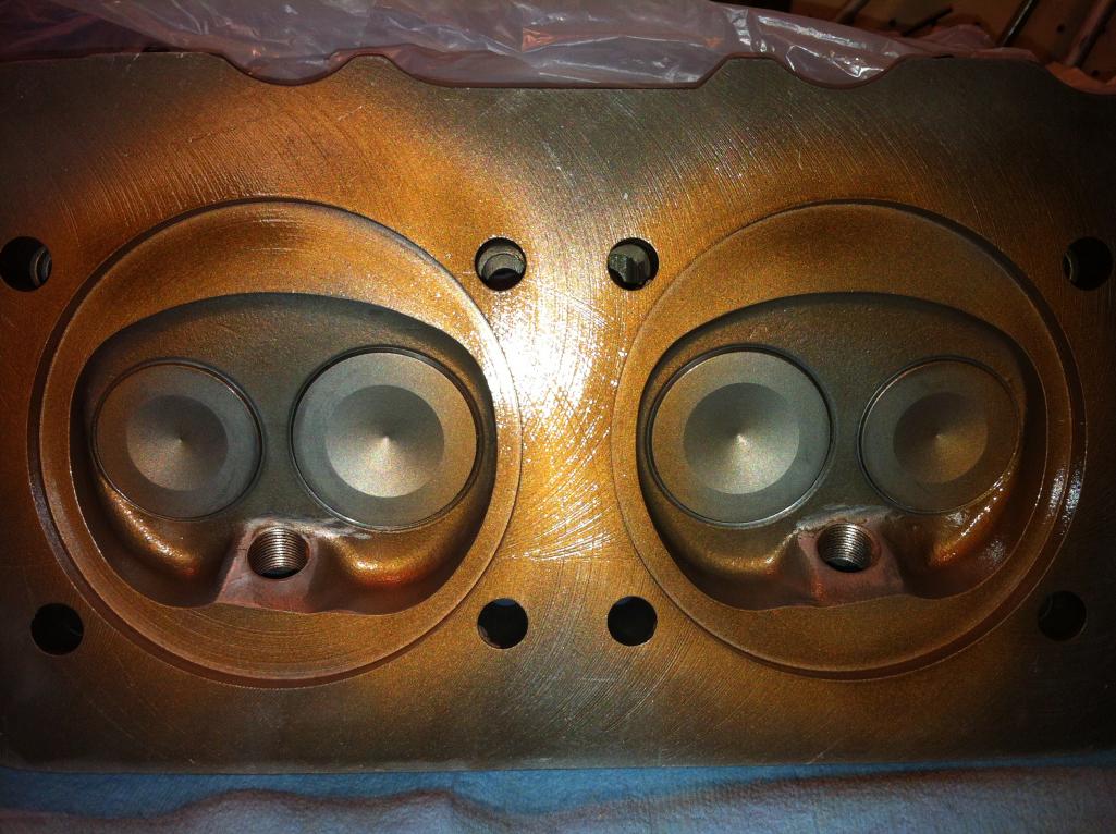 After the copper spray to help with the carbon seal. |
|
|
|
|
1 User(s) are reading this topic (1 Guests and 0 Anonymous Users)
0 Members:

|
Lo-Fi Version | Time is now: 28th April 2024 - 05:58 PM |
Invision Power Board
v9.1.4 © 2024 IPS, Inc.