Installed crank, gears, cam, and rods. Dry fit CB's dry sump pump and modified the tang and clearanced drive tang boss.
Click to view attachment
Full Version: 2056 Build
QUOTE(yeahmag @ Feb 1 2012, 10:49 PM) 
Installed crank, gears, cam, and rods. Dry fit CB's dry sump pump and modified the tang and clearanced drive tang boss.
Click to view attachment

Cool! Wish I had the guts to attempt a rebuild. One day!
Will the fan housing bolt up / clear the new pump ?? Or are using another cooling option ?? Looks good !!! 
Jack
Jack
what are you going to do about your engine mounts?
I will need to modify the fan housing to clear the oil pump. I will also have to custom make some motor mounts.
you are one step ahead of me. i am doing the same as you. same pump also.....
i just finished all my case mods, and concentrating on building my sump tank.
did you hav to grind your cam bolts? do you remember how much you took off the snout of the pump?
i am going to use tangerine racing's horizontal fan set up, so my engine mounts shouldnt be a problem.
i just finished all my case mods, and concentrating on building my sump tank.
did you hav to grind your cam bolts? do you remember how much you took off the snout of the pump?
i am going to use tangerine racing's horizontal fan set up, so my engine mounts shouldnt be a problem.
I ground about 2mm off that pump. Maybe more. I also made the tang have some angle at the end like the stock tangs. I made the tang length match the one I got from Raby years ago. I took a bit off the boss holding the drive tang to make sure it was clear of the cam. I probably took off 1mm at most on the boss.
I did grind my cam bolts to be safe, but I probably didn't have to with the ones Jake sent me.
What case mods did you do?
I did grind my cam bolts to be safe, but I probably didn't have to with the ones Jake sent me.
What case mods did you do?
since im not using the stock oil cooler or stock oil filter i took them out of the circuit. i also welded up the relief holes and took both relief system out of the circuit also. 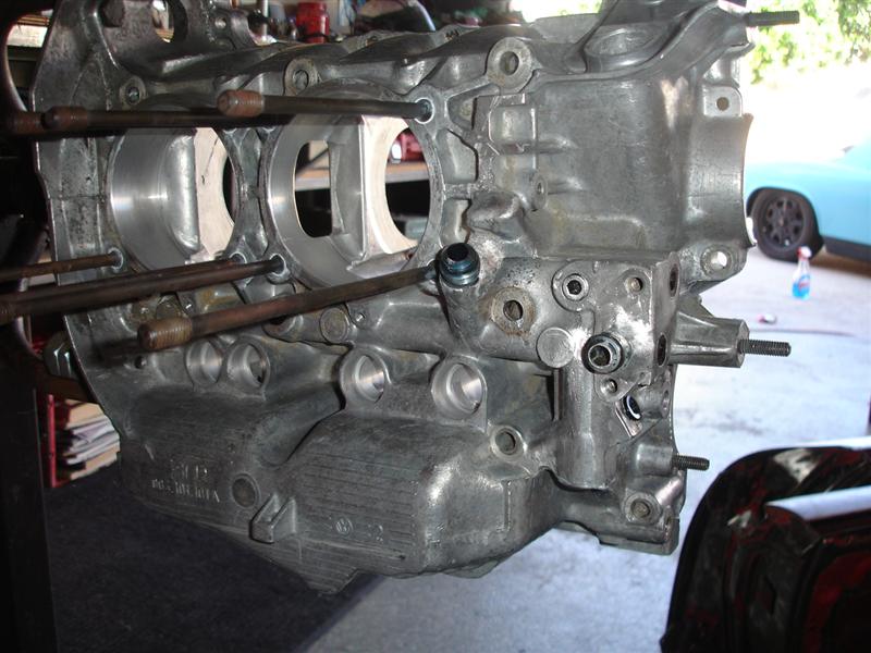
How are you routing the oil for the pressure stage? The galley from the pressure side of the pump goes right to the oil filter...
i used this diagram 
and modified it to this
1. jaycee 3 port remote oil filter/relief @ 80 psi
2. remote oil cooler
3. sump tank
in my picture you can see i welded a fitting on the passage from the pump (where the old filter stand was)
then it goes thru the remote filter, oil cooler, and then straight to the mains via the oil cooler location. another welded fitting. i just cut of the the old cooler stand off the case.
Here are pictures of the pistons after going through the ultrasonic cleaner and then me balancing them. I used a 1g scale, a 1/2" drill bit, and an air powered angle grinder with a small sanding disk (just to clean up any sharp edges). The all are at 570g now. They were as much a 3g out. Weights ranged from 570g to 573g.
Click to view attachment
Click to view attachment
Click to view attachment
Click to view attachment
QUOTE(mrbubblehead @ Feb 2 2012, 04:18 PM)
i used this diagram
and modified it to this
1. jaycee 3 port remote oil filter/relief @ 80 psi
2. remote oil cooler
3. sump tank
in my picture you can see i welded a fitting on the passage from the pump (where the old filter stand was)
then it goes thru the remote filter, oil cooler, and then straight to the mains via the oil cooler location. another welded fitting. i just cut of the the old cooler stand off the case.
So how do you pump oil out of the sump?

I was thinking the same thing. Somehow youi need to get the oil in the tank to the suction side of the pump. All the dry sump systems I've seen have a scavenge and a pressure pump.
QUOTE(jmill @ Feb 3 2012, 05:07 PM)
I was thinking the same thing. Somehow youi need to get the oil in the tank to the suction side of the pump. All the dry sump systems I've seen have a scavenge and a pressure pump.
i know, this diagram was just for me. i didnt draw them in because i know that the feed and return from the sump tank go to the oil pump. this diagram was to figure out how i was gonna get in and out of the case.
You are going to love that engine. 
any more progress yeahman? do you know what you are going to use for a sump tank yet?
Been cleaning parts like mad. Finally ready to close the case up after checking the fit of the drive tang and boss on the CB dry sump pump.
I also got around to modifying the oil filter housing. I used a slide hammer with a small, blind bearing pull attachment and removed the bypass system. I then cut an AL slug to fit and MIG'ed it in.
With regards to the tank, I'm using a very nice Patterson tank that Blake sold me. I'll be mounting it up front and trying to figure out how to mount an oil cooler up there too.
OK. The long block is together and I'm starting on the valve train geometry. Here are some pic's:
Click to view attachment
The head after using Ajax to lap the cylinders
Click to view attachment
The head after using Ajax to lap the cylinders
Click to view attachment
After the copper spray to help with the carbon seal.
After the copper spray to help with the carbon seal.
Click to view attachment
Long block together (more or less).
Long block together (more or less).
Click to view attachment
Ported the hell out of the CB Dry Sump Pump and made a custom engine bar bracket (which you can just barely make out).
Ported the hell out of the CB Dry Sump Pump and made a custom engine bar bracket (which you can just barely make out).
Click to view attachment
Shot of the heads with Jakes "super" option. 911 adjusters, new 8mm studs, solid spacers, etc...
That's all for now!
Shot of the heads with Jakes "super" option. 911 adjusters, new 8mm studs, solid spacers, etc...
That's all for now!
Those studs look to short to me.
And it looks to me that you need to shim the shafts more but that may be just the camera angle.
![popcorn[1].gif](http://www.914world.com/bbs2/style_emoticons/default/popcorn[1].gif)
And it looks to me that you need to shim the shafts more but that may be just the camera angle.
The nuts are just there to keep the rockers from falling off if I space and turn the motor over on the stand. In that shot I had *not* started setting the geometry.
Jake appears to like where I have my valve train geometry:
Intake: .438"
Exhaust: .412"
@ 50% lift adjuster and valve are perpendicular for both intake and exhaust.
1 full turn of adjustment available "in" available before bottoming out the foot with a .060" shim on the stands.
Click to view attachment
Off to cut the pushrods!
Intake: .438"
Exhaust: .412"
@ 50% lift adjuster and valve are perpendicular for both intake and exhaust.
1 full turn of adjustment available "in" available before bottoming out the foot with a .060" shim on the stands.
Click to view attachment
Off to cut the pushrods!
Measuring my pushrod tips using a flat table and a custom fixture made of fixture plate. Notice one of them differs by .002" - .003". Not sure if keying off the "flat" of the ball is valid, but still interesting to find one out of 8 with a variation.
Click to view attachment
Click to view attachment
Click to view attachment
Click to view attachment
I would not measure them this way. Error is much higher than the 0.03" you measured, mostly because the dial-meter is probably not perfectly perpendicular to the table, the arm holding it has some elasticity and moves and you're measuring a round surface.
I suggest you take a micrometer and measure the rod head with the holding jig and then subtract the jig width.
I suggest you take a micrometer and measure the rod head with the holding jig and then subtract the jig width.
Nah... The rig is designed for telescopes and is on a flat table. The table is accurate to .001" across the *entire* surface and the tool plate is accurate to .001" across a 3' length. This micrometer rig is over $10K and I can't even guess what that huge hunk of rock of a table cost.
We surfaced the plate on the same flat table to be sure and then ran the tool plate under the micrometer to make sure there were no deviations.
7 of the 8 tips all came back within .001". Just one came back at .003" out. This was absolutely repeatable. I did first check them with calipers, but the end of the taper is not machined and made it impossible to hold a tolerance.
In an ideal world I would be measuring centerline to centerline of the ball and not keying off the flats at the end as I suspect they are not machined to a tight tolerance there.
Here is a wider shot so you get a better feel for what we were doing.
Click to view attachment
That's no kitchen counter top!!!
Click to view attachment
That's no kitchen counter top!!!
The cost of the measuring equipment doesn't beat the physic laws 
This is all you need. Cheep and more accurate than your big setup for this measurement. The finest dust particle at the base of your long arm will be distort your measurement big time.
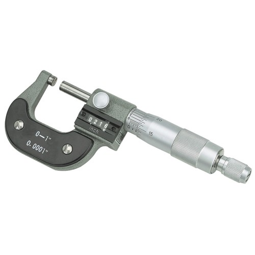
This is all you need. Cheep and more accurate than your big setup for this measurement. The finest dust particle at the base of your long arm will be distort your measurement big time.
I don't want to debat this too much, but this simply isn't the case. The primary problem with the method you are suggesting is that ***in my case*** the bottom of the tip (opposite the ball) is not machined to any specific tolerance. Other tips from other vendors may be different.
Additionally, you can't measure from the shoulder to the flat on the tip with that tool as the ball is smaller than the shoulder. You would be measuring on an angle... Again, that's how my pushrods and tips are. Others may be different.
The rig I used was repeatable, which if nothing else shows me variances between parts. The micrometer and it's arm is stationary and the tip and tool plate was moved in and out. I imagine Carnegie would have a hell of a lot of telescopes not working if this guy didn't know what the hell he was doing...
But in my book, building these things is half the fun. Do what works for you! I can't remember what Jake always says, but it's something like, "...this is where you become the engine builder."
QUOTE(yeahmag @ Jun 6 2012, 03:42 PM)
I don't want to debat this too much, but this simply isn't the case. The primary problem with the method you are suggesting is that ***in my case*** the bottom of the tip (opposite the ball) is not machined to any specific tolerance. Other tips from other vendors may be different.
Additionally, you can't measure from the shoulder to the flat on the tip with that tool as the ball is smaller than the shoulder. You would be measuring on an angle... Again, that's how my pushrods and tips are. Others may be different.
The rig I used was repeatable, which if nothing else shows me variances between parts. The micrometer and it's arm is stationary and the tip and tool plate was moved in and out. I imagine Carnegie would have a hell of a lot of telescopes not working if this guy didn't know what the hell he was doing...
But in my book, building these things is half the fun. Do what works for you! I can't remember what Jake always says, but it's something like, "...this is where you become the engine builder."
Well, you solved the problem of the not machined bottom tip with your little jig-plate and that's fine. You should have used that plate in a micrometer.
Anyway, it doesn't really make any difference as those tolerances can be compensated at the valve adjuster and the final lift difference is smaller than the deviation you measured.
And that deviation alone is not relevant. You need to measure the assembled valve train for meaningful results.
This weekend I finished my valve train. I ended up somewhat redoing my rockers as originally I had ground them by hand on a grinding wheel (over 7 years ago!) and used a caliper to try and keep them square. Previously I was using Ford Courier style adjusters (captured ball), this wasn't good enough for the 911 adjusters...
I jigged them in the mill with a carbide ball end mill (to give a radius at the arm) and made them all *exactly* the same thickness as the thinnest of the group. That got all my adjusters where I wanted them to be. It's amazing how far some of them were off!
Pushrod tubes were assembled with Viton o-rings and a little Loctite-565. Finished up with a "loose zero" valve adjustment.
Things should start to come together fast now!
While not quite part of the engine build I thought these interesting. Here is a picture of Chris' inner suspension console reinforcement piece all welded in:
Click to view attachment
Luckily the metal behind it was absolutely perfect. I was starting to get concerned due to running high spring rates (and wanting to go higher) along with DOT-R tires. Here it is painted:
Click to view attachment
We did both left and right sides with a TIG and in addition seamed welded as much of the ear as we could reach.
Click to view attachment
Luckily the metal behind it was absolutely perfect. I was starting to get concerned due to running high spring rates (and wanting to go higher) along with DOT-R tires. Here it is painted:
Click to view attachment
We did both left and right sides with a TIG and in addition seamed welded as much of the ear as we could reach.
It's been quite a while, but I have been working! I've got all the holes drilled in the chassis for the scavenge side and am working on the return now. I also finally made the breather set up that enlarges the case breather (-10AN in my case) and blocks off the heads.
Click to view attachment
Click to view attachment
Cool engine build!
John
Forgot to show the port matching of the CB manifolds to the stock, 2.0 head gaskets...
Click to view attachment
Click to view attachment
A few more... I have the scavenge line run up the passenger side, so it's time to get the oil cooler going. I got a Mercedes Benz oil cooler from Bruce and put a bend in it to match the curve of the front bumper. I then cut the original fittings off, welded them shut, and added -10AN fittings to the ends of the tank (vs. the face as original).
Click to view attachment
Click to view attachment
Click to view attachment
Click to view attachment
Cool engine build- oh thanks for the education too.
QUOTE(yeahmag @ May 24 2012, 01:25 PM)
Click to view attachment
Ported the hell out of the CB Dry Sump Pump and made a custom engine bar bracket (which you can just barely make out).
Where does the engine bar bracket bolt into the case? Just the two lower bolts or does it mount in another place as well?
Just the two lowers.
Some craptastic iPhone photos of the progress. Passenger side scavenge side oil line run and the holes are drilled for the drivers side return. I still have to actually hook the lines up and clean up the install a bit.
Click to view attachment
Click to view attachment
Click to view attachment
Click to view attachment
looks good. what size is that? -8, -10?
-10 on the scavenge side. -12 for most of the run, necking down to -10 at the very end for the return.
Nice! When do you fire it?
how did you bend the oil cooler?
I bent the cooler in a press supporting it with 2x4's and then another 2x4 perpendicular in the middle to distribute the load. It's not perfect, but should work.
Not real sure when I'll start it, I'm guessing early January.
Not real sure when I'll start it, I'm guessing early January.
QUOTE(yeahmag @ Dec 12 2012, 08:56 AM)
I bent the cooler in a press supporting it with 2x4's and then another 2x4 perpendicular in the middle to distribute the load. It's not perfect, but should work.
Not real sure when I'll start it, I'm guessing early January.
Nice work Aaron.....gotta get those cobwebs off the longs!

This is a "lo-fi" version of our main content. To view the full version with more information, formatting and images, please click here.