|
|
|
Porsche, and the Porsche crest are registered trademarks of Dr. Ing. h.c. F. Porsche AG.
This site is not affiliated with Porsche in any way. Its only purpose is to provide an online forum for car enthusiasts. All other trademarks are property of their respective owners. |
|
|

  |

| yeahmag |
 May 24 2012, 12:24 PM May 24 2012, 12:24 PM
Post
#21
|
|
Advanced Member  Group: Members Posts: 2,468 Joined: 18-April 05 From: Pasadena, CA Member No.: 3,946 Region Association: Southern California |
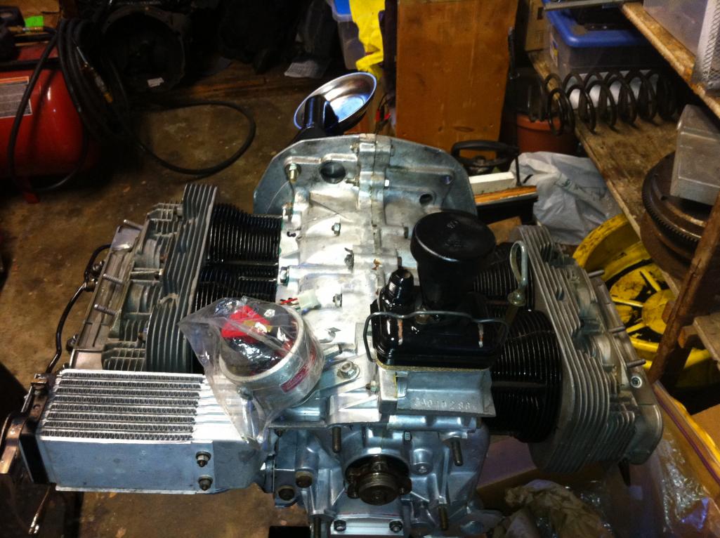 Long block together (more or less). |
   |

 
|
| yeahmag |
May 24 2012, 12:25 PM
Post
#22
|
|
Advanced Member Group: Members Posts: 2,468 Joined: 18-April 05 From: Pasadena, CA Member No.: 3,946 Region Association: Southern California |
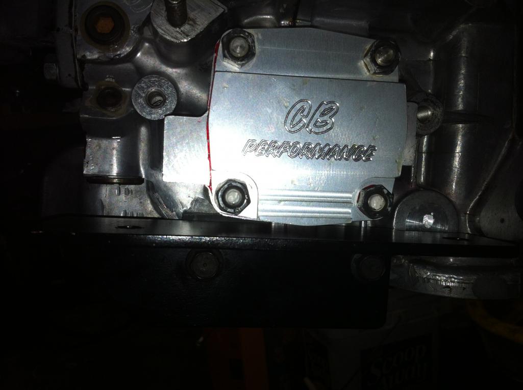 Ported the hell out of the CB Dry Sump Pump and made a custom engine bar bracket (which you can just barely make out). |
|
|
|
| yeahmag |
May 24 2012, 12:26 PM
Post
#23
|
|
Advanced Member Group: Members Posts: 2,468 Joined: 18-April 05 From: Pasadena, CA Member No.: 3,946 Region Association: Southern California |
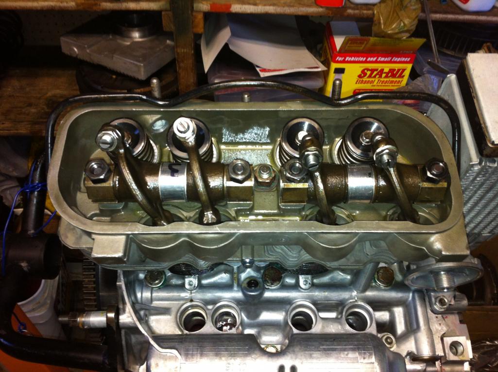 Shot of the heads with Jakes "super" option. 911 adjusters, new 8mm studs, solid spacers, etc... That's all for now! |
|
|
|
| Valy |
May 24 2012, 01:39 PM
Post
#24
|
|
Senior Member Group: Members Posts: 1,677 Joined: 6-April 10 From: Sunnyvale, CA Member No.: 11,573 Region Association: Northern California |
Those studs look to short to me.
And it looks to me that you need to shim the shafts more but that may be just the camera angle. (IMG:style_emoticons/default/popcorn[1].gif) |
|
|
|
| yeahmag |
May 24 2012, 02:10 PM
Post
#25
|
|
Advanced Member Group: Members Posts: 2,468 Joined: 18-April 05 From: Pasadena, CA Member No.: 3,946 Region Association: Southern California |
The nuts are just there to keep the rockers from falling off if I space and turn the motor over on the stand. In that shot I had *not* started setting the geometry.
|
|
|
|
| yeahmag |
May 29 2012, 06:05 PM
Post
#26
|
|
Advanced Member Group: Members Posts: 2,468 Joined: 18-April 05 From: Pasadena, CA Member No.: 3,946 Region Association: Southern California |
Jake appears to like where I have my valve train geometry:
Intake: .438" Exhaust: .412" @ 50% lift adjuster and valve are perpendicular for both intake and exhaust. 1 full turn of adjustment available "in" available before bottoming out the foot with a .060" shim on the stands. 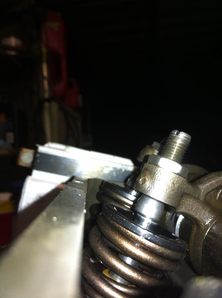 Off to cut the pushrods! |
|
|
|
| yeahmag |
Jun 6 2012, 12:19 PM
Post
#27
|
|
Advanced Member Group: Members Posts: 2,468 Joined: 18-April 05 From: Pasadena, CA Member No.: 3,946 Region Association: Southern California |
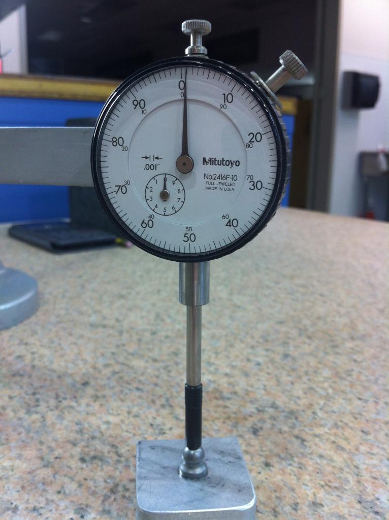
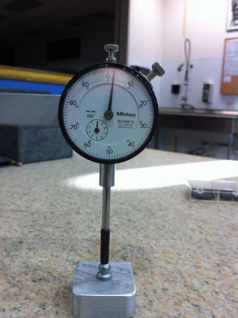
Measuring my pushrod tips using a flat table and a custom fixture made of fixture plate. Notice one of them differs by .002" - .003". Not sure if keying off the "flat" of the ball is valid, but still interesting to find one out of 8 with a variation.
  |
|
|
|
| Valy |
Jun 6 2012, 03:40 PM
Post
#28
|
|
Senior Member Group: Members Posts: 1,677 Joined: 6-April 10 From: Sunnyvale, CA Member No.: 11,573 Region Association: Northern California |
I would not measure them this way. Error is much higher than the 0.03" you measured, mostly because the dial-meter is probably not perfectly perpendicular to the table, the arm holding it has some elasticity and moves and you're measuring a round surface.
I suggest you take a micrometer and measure the rod head with the holding jig and then subtract the jig width. |
|
|
|
| yeahmag |
Jun 6 2012, 04:14 PM
Post
#29
|
|
Advanced Member Group: Members Posts: 2,468 Joined: 18-April 05 From: Pasadena, CA Member No.: 3,946 Region Association: Southern California |
Nah... The rig is designed for telescopes and is on a flat table. The table is accurate to .001" across the *entire* surface and the tool plate is accurate to .001" across a 3' length. This micrometer rig is over $10K and I can't even guess what that huge hunk of rock of a table cost.
We surfaced the plate on the same flat table to be sure and then ran the tool plate under the micrometer to make sure there were no deviations. 7 of the 8 tips all came back within .001". Just one came back at .003" out. This was absolutely repeatable. I did first check them with calipers, but the end of the taper is not machined and made it impossible to hold a tolerance. In an ideal world I would be measuring centerline to centerline of the ball and not keying off the flats at the end as I suspect they are not machined to a tight tolerance there. |
|
|
|
| yeahmag |
Jun 6 2012, 04:16 PM
Post
#30
|
|
Advanced Member Group: Members Posts: 2,468 Joined: 18-April 05 From: Pasadena, CA Member No.: 3,946 Region Association: Southern California |
Here is a wider shot so you get a better feel for what we were doing.
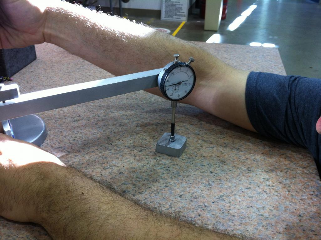 That's no kitchen counter top!!! |
|
|
|
| Valy |
Jun 6 2012, 04:24 PM
Post
#31
|
|
Senior Member Group: Members Posts: 1,677 Joined: 6-April 10 From: Sunnyvale, CA Member No.: 11,573 Region Association: Northern California |
The cost of the measuring equipment doesn't beat the physic laws (IMG:style_emoticons/default/smile.gif)
This is all you need. Cheep and more accurate than your big setup for this measurement. The finest dust particle at the base of your long arm will be distort your measurement big time. (IMG:http://www.914world.com/bbs2/uploads_offsite/www.harborfreight.com-11573-1339021494.1.jpg) |
|
|
|
| yeahmag |
Jun 6 2012, 04:42 PM
Post
#32
|
|
Advanced Member Group: Members Posts: 2,468 Joined: 18-April 05 From: Pasadena, CA Member No.: 3,946 Region Association: Southern California |
I don't want to debat this too much, but this simply isn't the case. The primary problem with the method you are suggesting is that ***in my case*** the bottom of the tip (opposite the ball) is not machined to any specific tolerance. Other tips from other vendors may be different.
Additionally, you can't measure from the shoulder to the flat on the tip with that tool as the ball is smaller than the shoulder. You would be measuring on an angle... Again, that's how my pushrods and tips are. Others may be different. The rig I used was repeatable, which if nothing else shows me variances between parts. The micrometer and it's arm is stationary and the tip and tool plate was moved in and out. I imagine Carnegie would have a hell of a lot of telescopes not working if this guy didn't know what the hell he was doing... But in my book, building these things is half the fun. Do what works for you! I can't remember what Jake always says, but it's something like, "...this is where you become the engine builder." |
|
|
|
| Valy |
Jun 6 2012, 05:39 PM
Post
#33
|
|
Senior Member Group: Members Posts: 1,677 Joined: 6-April 10 From: Sunnyvale, CA Member No.: 11,573 Region Association: Northern California |
QUOTE(yeahmag @ Jun 6 2012, 03:42 PM)  I don't want to debat this too much, but this simply isn't the case. The primary problem with the method you are suggesting is that ***in my case*** the bottom of the tip (opposite the ball) is not machined to any specific tolerance. Other tips from other vendors may be different. Additionally, you can't measure from the shoulder to the flat on the tip with that tool as the ball is smaller than the shoulder. You would be measuring on an angle... Again, that's how my pushrods and tips are. Others may be different. The rig I used was repeatable, which if nothing else shows me variances between parts. The micrometer and it's arm is stationary and the tip and tool plate was moved in and out. I imagine Carnegie would have a hell of a lot of telescopes not working if this guy didn't know what the hell he was doing... But in my book, building these things is half the fun. Do what works for you! I can't remember what Jake always says, but it's something like, "...this is where you become the engine builder." Well, you solved the problem of the not machined bottom tip with your little jig-plate and that's fine. You should have used that plate in a micrometer. Anyway, it doesn't really make any difference as those tolerances can be compensated at the valve adjuster and the final lift difference is smaller than the deviation you measured. And that deviation alone is not relevant. You need to measure the assembled valve train for meaningful results. |
|
|
|
| yeahmag |
Jun 11 2012, 12:22 PM
Post
#34
|
|
Advanced Member Group: Members Posts: 2,468 Joined: 18-April 05 From: Pasadena, CA Member No.: 3,946 Region Association: Southern California |
This weekend I finished my valve train. I ended up somewhat redoing my rockers as originally I had ground them by hand on a grinding wheel (over 7 years ago!) and used a caliper to try and keep them square. Previously I was using Ford Courier style adjusters (captured ball), this wasn't good enough for the 911 adjusters...
I jigged them in the mill with a carbide ball end mill (to give a radius at the arm) and made them all *exactly* the same thickness as the thinnest of the group. That got all my adjusters where I wanted them to be. It's amazing how far some of them were off! Pushrod tubes were assembled with Viton o-rings and a little Loctite-565. Finished up with a "loose zero" valve adjustment. Things should start to come together fast now! |
|
|
|
| yeahmag |
Aug 16 2012, 11:19 AM
Post
#35
|
|
Advanced Member Group: Members Posts: 2,468 Joined: 18-April 05 From: Pasadena, CA Member No.: 3,946 Region Association: Southern California |
While not quite part of the engine build I thought these interesting. Here is a picture of Chris' inner suspension console reinforcement piece all welded in:
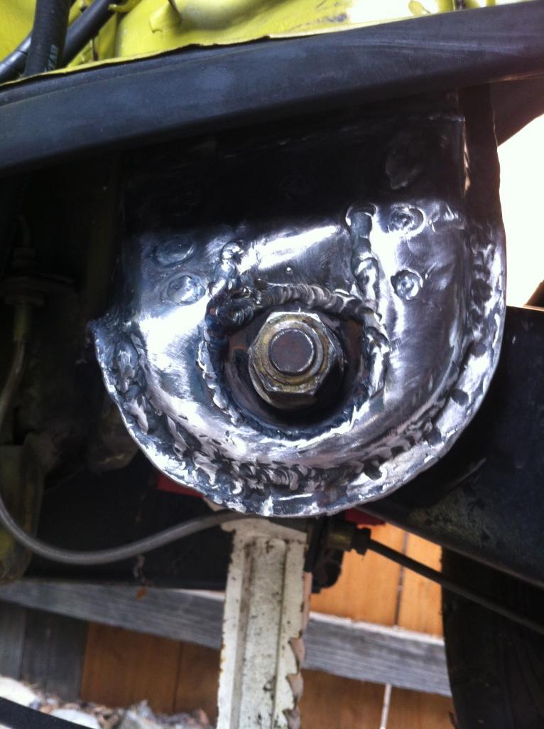 Luckily the metal behind it was absolutely perfect. I was starting to get concerned due to running high spring rates (and wanting to go higher) along with DOT-R tires. Here it is painted: 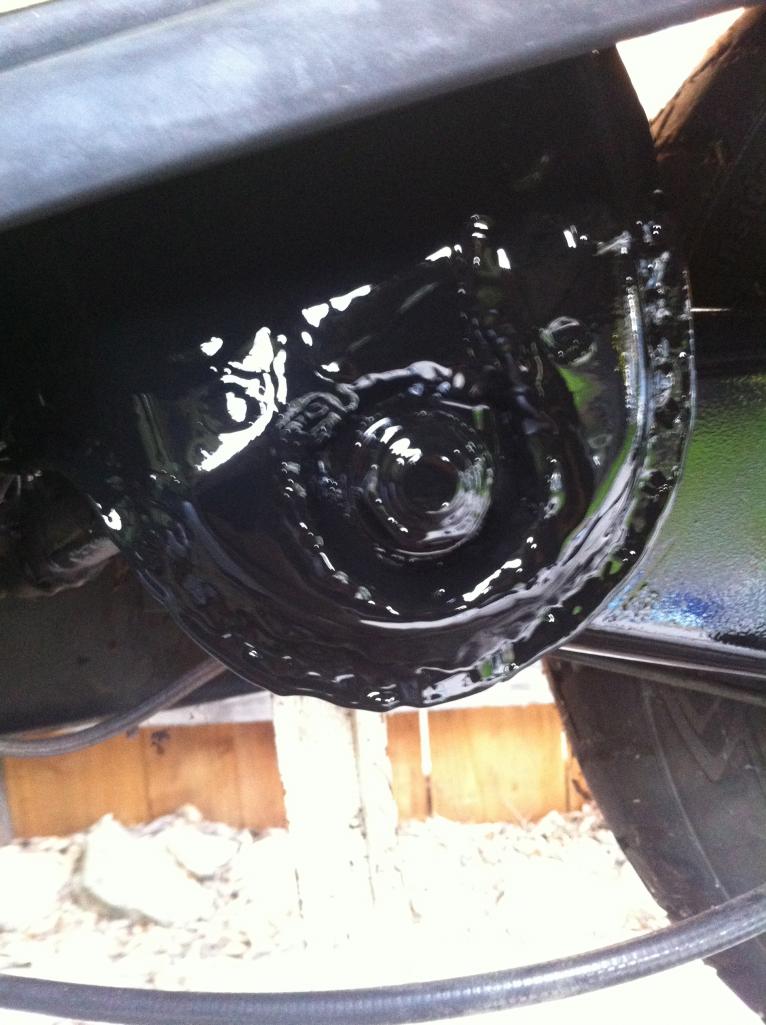 We did both left and right sides with a TIG and in addition seamed welded as much of the ear as we could reach. |
|
|
|
| yeahmag |
Nov 5 2012, 11:47 AM
Post
#36
|
|
Advanced Member Group: Members Posts: 2,468 Joined: 18-April 05 From: Pasadena, CA Member No.: 3,946 Region Association: Southern California |
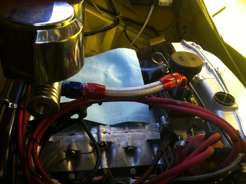
It's been quite a while, but I have been working! I've got all the holes drilled in the chassis for the scavenge side and am working on the return now. I also finally made the breather set up that enlarges the case breather (-10AN in my case) and blocks off the heads.
 |
|
|
|
| FourBlades |
Nov 5 2012, 12:30 PM
Post
#37
|
|
From Wreck to Rockin Group: Members Posts: 2,056 Joined: 3-December 07 From: Brevard, FL Member No.: 8,414 Region Association: South East States |
|
|
|
|
| yeahmag |
Nov 5 2012, 04:59 PM
Post
#38
|
|
Advanced Member Group: Members Posts: 2,468 Joined: 18-April 05 From: Pasadena, CA Member No.: 3,946 Region Association: Southern California |
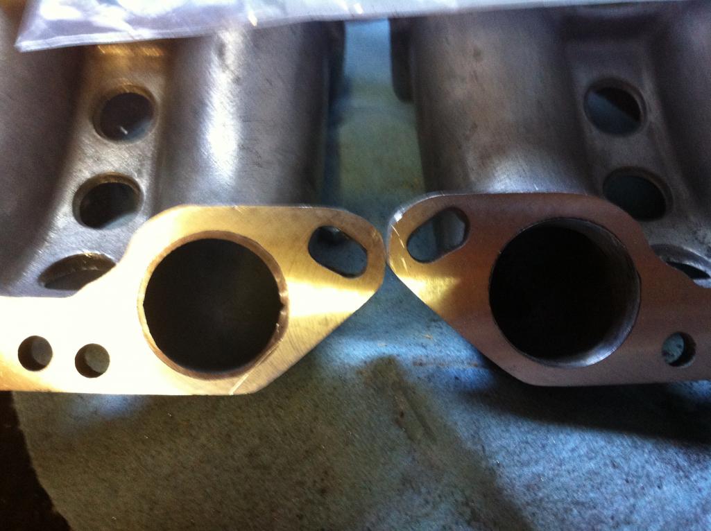
Forgot to show the port matching of the CB manifolds to the stock, 2.0 head gaskets...
 |
|
|
|
| yeahmag |
Nov 25 2012, 09:07 PM
Post
#39
|
|
Advanced Member Group: Members Posts: 2,468 Joined: 18-April 05 From: Pasadena, CA Member No.: 3,946 Region Association: Southern California |
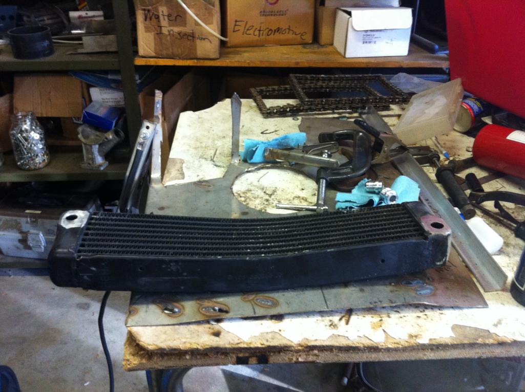
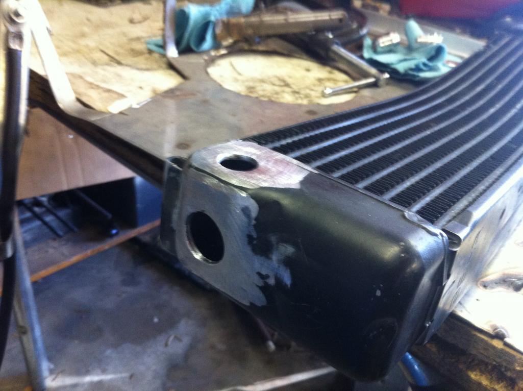
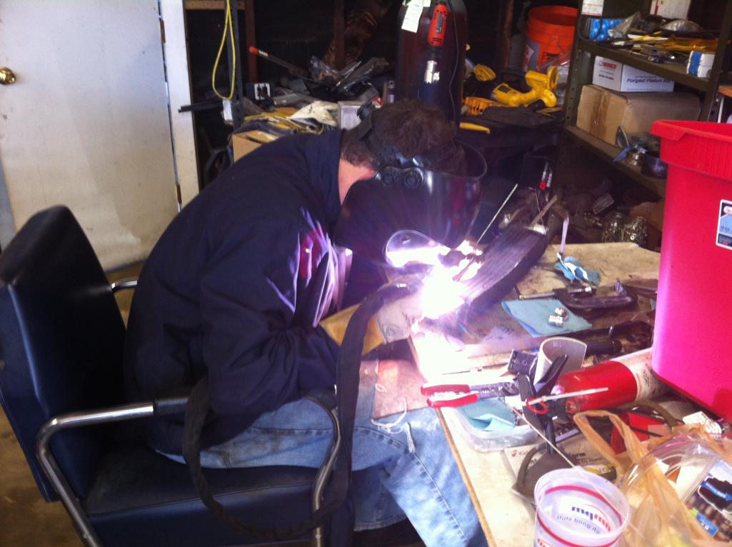
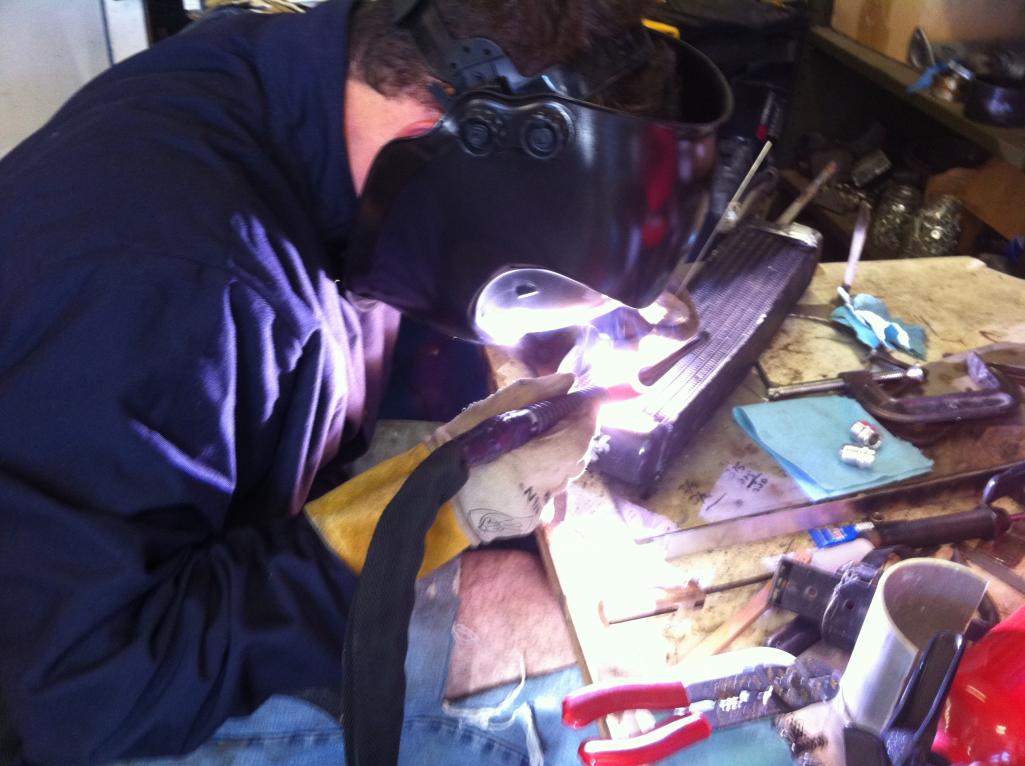
A few more... I have the scavenge line run up the passenger side, so it's time to get the oil cooler going. I got a Mercedes Benz oil cooler from Bruce and put a bend in it to match the curve of the front bumper. I then cut the original fittings off, welded them shut, and added -10AN fittings to the ends of the tank (vs. the face as original).
  |
|
|
|
| yeahmag |
Nov 25 2012, 09:08 PM
Post
#40
|
|
Advanced Member Group: Members Posts: 2,468 Joined: 18-April 05 From: Pasadena, CA Member No.: 3,946 Region Association: Southern California |
  |
|
|
|
|
2 User(s) are reading this topic (2 Guests and 0 Anonymous Users)
0 Members:

|
Lo-Fi Version | Time is now: 23rd October 2025 - 08:17 PM |
Invision Power Board
v9.1.4 © 2025 IPS, Inc.