|
|
|
Porsche, and the Porsche crest are registered trademarks of Dr. Ing. h.c. F. Porsche AG.
This site is not affiliated with Porsche in any way. Its only purpose is to provide an online forum for car enthusiasts. All other trademarks are property of their respective owners. |
|
|

  |

| Mike Bellis |
 Mar 22 2012, 08:42 PM Mar 22 2012, 08:42 PM
Post
#41
|
|
Resident Electrician  Group: Members Posts: 8,345 Joined: 22-June 09 From: Midlothian TX Member No.: 10,496 Region Association: None |
The MS fire bank to bank. It doesent really matter which way you hook it up. It fires, left, right, left, right... If it were sequencial, you would need to line it up per cylinder.
|
   |

 
|
| falconfp2001 |
Mar 23 2012, 12:44 AM
Post
#42
|
|
Pancho Pantera Group: Members Posts: 451 Joined: 5-December 10 From: Downey, CA Member No.: 12,456 Region Association: Southwest Region |
QUOTE(kg6dxn @ Mar 22 2012, 07:42 PM)  The MS fire bank to bank. It doesent really matter which way you hook it up. It fires, left, right, left, right... If it were sequencial, you would need to line it up per cylinder. So, just to clarify, we are talking injectors and not ignition? It sounds like a wasted spark type thing. |
|
|
|
| rwilner |
Mar 23 2012, 06:56 AM
Post
#43
|
|
No Ghosts in the Machine Group: Members Posts: 953 Joined: 30-March 10 From: Boston, MA Member No.: 11,530 Region Association: North East States |
QUOTE(falconfp2001 @ Mar 23 2012, 02:44 AM) QUOTE(kg6dxn @ Mar 22 2012, 07:42 PM) The MS fire bank to bank. It doesent really matter which way you hook it up. It fires, left, right, left, right... If it were sequencial, you would need to line it up per cylinder. So, just to clarify, we are talking injectors and not ignition? It sounds like a wasted spark type thing. depending on options you can set MS to fire as sequential or wasted spark, or sequential or batch injection. The simplest method that works great is batch injection with wasted spark. |
|
|
|
| JamesM |
Mar 23 2012, 07:51 AM
Post
#44
|
|
Senior Member Group: Members Posts: 1,915 Joined: 6-April 06 From: Kearns, UT Member No.: 5,834 Region Association: Intermountain Region |
QUOTE(rwilner @ Mar 23 2012, 04:56 AM) QUOTE(falconfp2001 @ Mar 23 2012, 02:44 AM) QUOTE(kg6dxn @ Mar 22 2012, 07:42 PM) The MS fire bank to bank. It doesent really matter which way you hook it up. It fires, left, right, left, right... If it were sequencial, you would need to line it up per cylinder. So, just to clarify, we are talking injectors and not ignition? It sounds like a wasted spark type thing. depending on options you can set MS to fire as sequential or wasted spark, or sequential or batch injection. The simplest method that works great is batch injection with wasted spark. Only MS2-Extra or MS3 firmware supports sequential injection and you need extra hardware (like a crank AND a cam sensor) to do it. Not much benifit to it either due to injector pulsewidth overlapping with valve timing at higher RPM anyways. You would be putting a lot of extra work in for little if any gain. |
|
|
|
| falconfp2001 |
Mar 26 2012, 11:38 PM
Post
#45
|
|
Pancho Pantera Group: Members Posts: 451 Joined: 5-December 10 From: Downey, CA Member No.: 12,456 Region Association: Southwest Region |
got an Update.
I had a little time but I ran out of sun and decided I'll finish up in the morning then head off to work. Installed my O2 Sensor. This pic shows where the bung was welded. The second pic shows where I drilled to pass it through the fire wall. It goes about an inch right of the shift rod. Attached thumbnail(s) 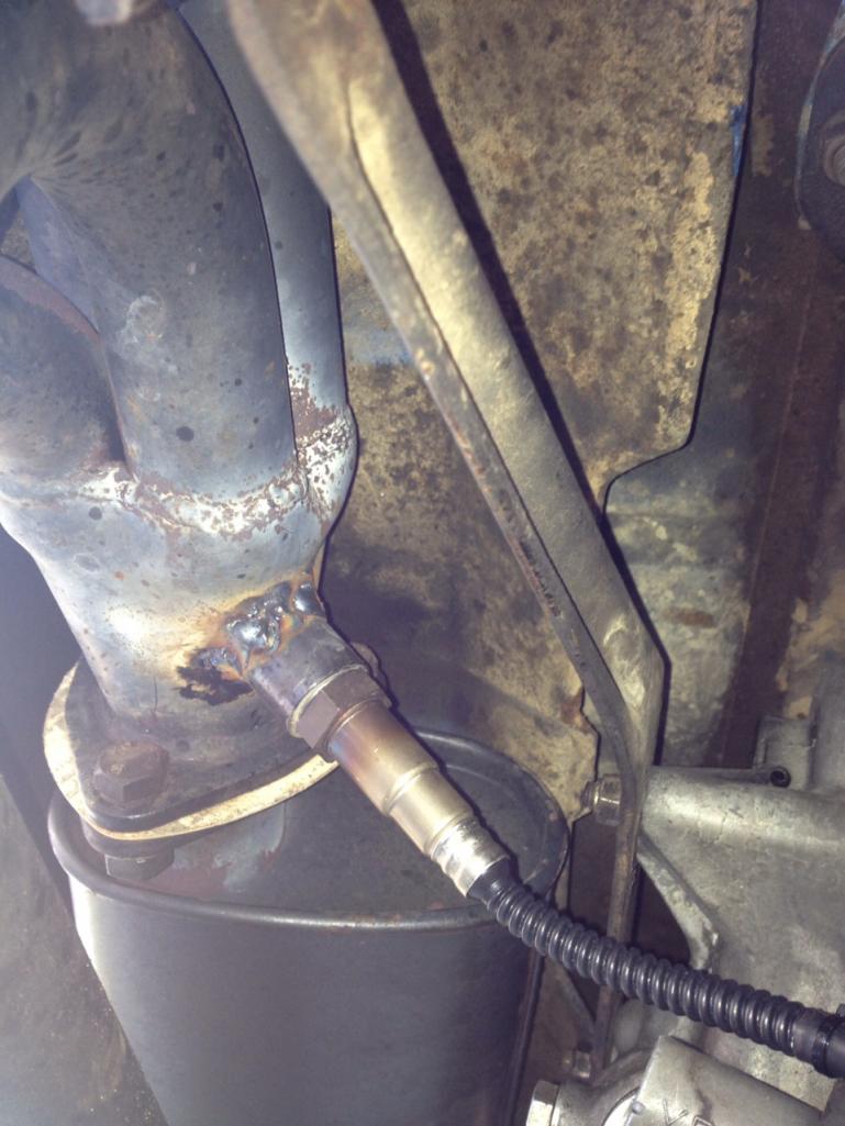 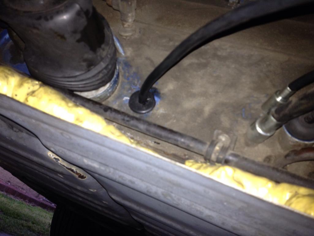
|
|
|
|
| falconfp2001 |
Mar 26 2012, 11:40 PM
Post
#46
|
|
Pancho Pantera Group: Members Posts: 451 Joined: 5-December 10 From: Downey, CA Member No.: 12,456 Region Association: Southwest Region |
This compares the cables. I'm going to just tie it to the main harness and run it up under the carpet behind the dash.
Attached thumbnail(s) 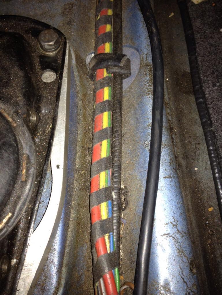 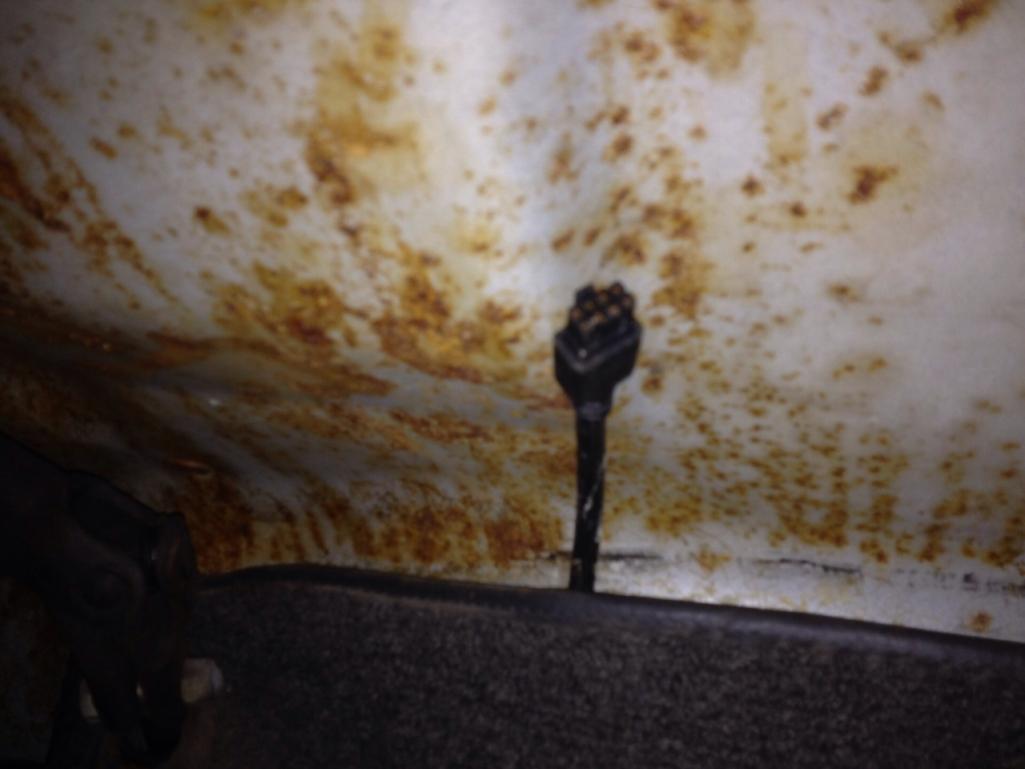
|
|
|
|
| falconfp2001 |
Mar 26 2012, 11:56 PM
Post
#47
|
|
Pancho Pantera Group: Members Posts: 451 Joined: 5-December 10 From: Downey, CA Member No.: 12,456 Region Association: Southwest Region |
I'll take some picks tomorrow after wiring it up.
This is the Innovate MTX-L. Over all length was 12' and it fit perfectly from the muffler all the way to the dash. I'm going to mount the Gauge off of the Ash Tray. I wired it using switched 12v from the Fuse Panel under the dash. The fuse panel is setup to have power flowing from top to bottom and there are several open spades for adding accessories. Or just buy a spade jumper at a local Auto Parts. Be careful as all the red wires to the right on the fuse panel are hot without the key on. I used a circuit tester that I ground, then tested the next fuse left of the last red and it was cold. Turned the key to on, and it was hot. It had an open spade connection so I crimped a female spade and plugged it in. With this Gauge, you have to also find the headlight source which is a yellow wire off the fuse panel but I just crimped a female spade and plugged in to the open connector next to it because they are both hot when the headlights are on and cold with them off. The purpose of this is to dim the gauge when it is dark out. I'll test and calibrate tomorrow. |
|
|
|
| falconfp2001 |
Mar 27 2012, 12:02 AM
Post
#48
|
|
Pancho Pantera Group: Members Posts: 451 Joined: 5-December 10 From: Downey, CA Member No.: 12,456 Region Association: Southwest Region |
Next Picture.
I tested the TPS and the wiring is as follows. Black = +5v Reference Yellow = Sensor return Brown = Ground (like all German autos) All of the wires tested perfectly when I hooked up to my multimeter. I stripped the shield all the way back and took off the boot without ripping it. I'll look for a pin tool tomorrow to take out the pins and re crimp the connections to a paired shielded cable and also the common ground. before soldering to make permanent. Next project for this plenum is to cut off the Temp Sensor and drill for mounting the GM open element style sensor. I purchased a flanged bung so It should mount fairly easy. Attached thumbnail(s) 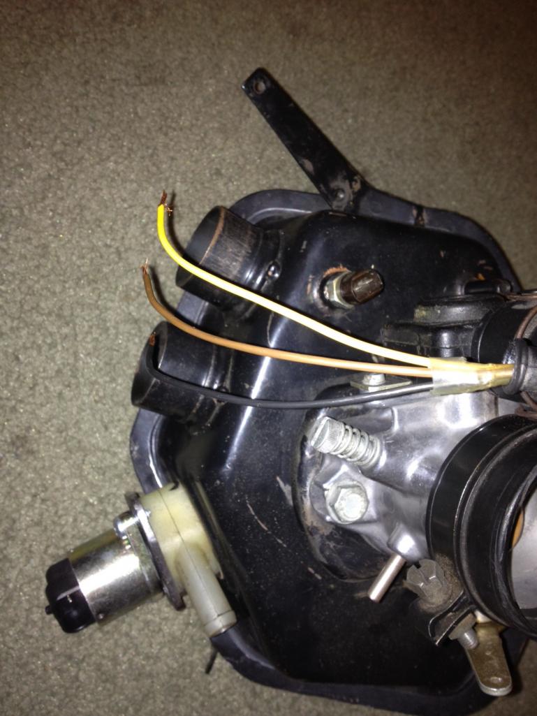
|
|
|
|
| JamesM |
Mar 27 2012, 12:46 PM
Post
#49
|
|
Senior Member Group: Members Posts: 1,915 Joined: 6-April 06 From: Kearns, UT Member No.: 5,834 Region Association: Intermountain Region |
QUOTE(falconfp2001 @ Mar 26 2012, 10:02 PM) Next Picture. I tested the TPS and the wiring is as follows. Black = +5v Reference Yellow = Sensor return Brown = Ground (like all German autos) All of the wires tested perfectly when I hooked up to my multimeter. I stripped the shield all the way back and took off the boot without ripping it. I'll look for a pin tool tomorrow to take out the pins and re crimp the connections to a paired shielded cable and also the common ground. before soldering to make permanent. Next project for this plenum is to cut off the Temp Sensor and drill for mounting the GM open element style sensor. I purchased a flanged bung so It should mount fairly easy. That stock temp sensor will work, you just need to tweak the values in MS. The open element sensor might be a bit better though as the stock sensor tends to get a lot of heatsoak, especally after a hot restart. |
|
|
|
| JamesM |
Mar 27 2012, 12:54 PM
Post
#50
|
|
Senior Member Group: Members Posts: 1,915 Joined: 6-April 06 From: Kearns, UT Member No.: 5,834 Region Association: Intermountain Region |
QUOTE(falconfp2001 @ Mar 26 2012, 10:02 PM) Next Picture. I tested the TPS and the wiring is as follows. Black = +5v Reference Yellow = Sensor return Brown = Ground (like all German autos) All of the wires tested perfectly when I hooked up to my multimeter. I stripped the shield all the way back and took off the boot without ripping it. I'll look for a pin tool tomorrow to take out the pins and re crimp the connections to a paired shielded cable and also the common ground. before soldering to make permanent. Next project for this plenum is to cut off the Temp Sensor and drill for mounting the GM open element style sensor. I purchased a flanged bung so It should mount fairly easy. Another thought on this. If you are going to chage the sensor to the GM one you might want to leave the stock sensor in place and mount the GM sensor somewhere that is more directly in the airflow, like the air cleaner snorkle. the 1.7 places the sensor in a good place right after the TB but the 2.0 location is sort of tucked up out of the way. |
|
|
|
| falconfp2001 |
Mar 27 2012, 01:10 PM
Post
#51
|
|
Pancho Pantera Group: Members Posts: 451 Joined: 5-December 10 From: Downey, CA Member No.: 12,456 Region Association: Southwest Region |
QUOTE(falconfp2001 @ Mar 26 2012, 10:56 PM) I'll take some picks tomorrow after wiring it up. This is the Innovate MTX-L. Over all length was 12' and it fit perfectly from the muffler all the way to the dash. I'm going to mount the Gauge off of the Ash Tray. I wired it using switched 12v from the Fuse Panel under the dash. The fuse panel is setup to have power flowing from top to bottom and there are several open spades for adding accessories. Or just buy a spade jumper at a local Auto Parts. Be careful as all the red wires to the right on the fuse panel are hot without the key on. I used a circuit tester that I ground, then tested the next fuse left of the last red and it was cold. Turned the key to on, and it was hot. It had an open spade connection so I crimped a female spade and plugged it in. With this Gauge, you have to also find the headlight source which is a yellow wire off the fuse panel but I just crimped a female spade and plugged in to the open connector next to it because they are both hot when the headlights are on and cold with them off. The purpose of this is to dim the gauge when it is dark out. I'll test and calibrate tomorrow. Just got the O2 sensor calibrated and the Gauge mounted and wired. Looks nice. If I add another Gauge later I'll get the combo panel. Right now its the only extra Gauge I have but looks good. As soon as I wired it up, I noticed my AFR was way off (as I suspected after my last visit to my Mechanic) so, I did some adjusting after I warmed up the engine. Couldn't get the mixture right with my ECU idle mixture knob so I moved on to the fuel pressure regulator. Not surprisingly the mounting nut for the regulator was loose (must have been the mechanic). So, I tightened that, loosened up the lock nut on the adjustment bolt and adjusted to get the right AFR. Some of you are probably cringing right now because I didn't use a pressure gauge. I'll do that later. I then let the car idle for about 20 minutes, then revved to 3000 and held for five minutes. idled for five, revved for five, idled for five. All while checking the AFR. Engine was ate peak now and I was able to then adjust AFR with the ECU and the idle speed with the control screw on the TB. Runs better. Attached thumbnail(s) 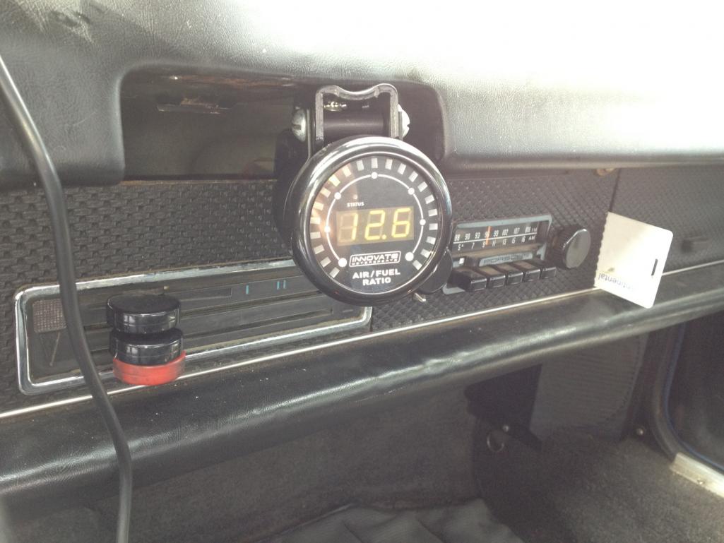
|
|
|
|
| falconfp2001 |
Mar 27 2012, 01:24 PM
Post
#52
|
|
Pancho Pantera Group: Members Posts: 451 Joined: 5-December 10 From: Downey, CA Member No.: 12,456 Region Association: Southwest Region |
QUOTE(JamesM @ Mar 27 2012, 11:46 AM) QUOTE(falconfp2001 @ Mar 26 2012, 10:02 PM) Next Picture. I tested the TPS and the wiring is as follows. Black = +5v Reference Yellow = Sensor return Brown = Ground (like all German autos) All of the wires tested perfectly when I hooked up to my multimeter. I stripped the shield all the way back and took off the boot without ripping it. I'll look for a pin tool tomorrow to take out the pins and re crimp the connections to a paired shielded cable and also the common ground. before soldering to make permanent. Next project for this plenum is to cut off the Temp Sensor and drill for mounting the GM open element style sensor. I purchased a flanged bung so It should mount fairly easy. That stock temp sensor will work, you just need to tweak the values in MS. The open element sensor might be a bit better though as the stock sensor tends to get a lot of heatsoak, especally after a hot restart. That is why I purchased the GM IAT. Most people claim this is vapor lock but it's simply that the actually Air temp is off in the ECU. Once started, the sensor will start to cool due to air flow but it depends on how long the engine sat. The GM IAT looks a little insulated and of course, exposed so it quickly adjusts to actual air temp. I'll need to apply some epoxy to the exposed wires under the element before installing |
|
|
|
| falconfp2001 |
Mar 27 2012, 01:43 PM
Post
#53
|
|
Pancho Pantera Group: Members Posts: 451 Joined: 5-December 10 From: Downey, CA Member No.: 12,456 Region Association: Southwest Region |
QUOTE(falconfp2001 @ Mar 27 2012, 12:24 PM) QUOTE(JamesM @ Mar 27 2012, 11:46 AM) QUOTE(falconfp2001 @ Mar 26 2012, 10:02 PM) Next Picture. I tested the TPS and the wiring is as follows. Black = +5v Reference Yellow = Sensor return Brown = Ground (like all German autos) All of the wires tested perfectly when I hooked up to my multimeter. I stripped the shield all the way back and took off the boot without ripping it. I'll look for a pin tool tomorrow to take out the pins and re crimp the connections to a paired shielded cable and also the common ground. before soldering to make permanent. Next project for this plenum is to cut off the Temp Sensor and drill for mounting the GM open element style sensor. I purchased a flanged bung so It should mount fairly easy. That stock temp sensor will work, you just need to tweak the values in MS. The open element sensor might be a bit better though as the stock sensor tends to get a lot of heatsoak, especally after a hot restart. That is why I purchased the GM IAT. Most people claim this is vapor lock but it's simply that the actually Air temp is off in the ECU. Once started, the sensor will start to cool due to air flow but it depends on how long the engine sat. The GM IAT looks a little insulated and of course, exposed so it quickly adjusts to actual air temp. I'll need to apply some epoxy to the exposed wires under the element before installing Here's a shot of the IAT. 3/8 NPT bung. You can just see the element that is only held in place by two small solid wires. Some break due to vibration so they recommend using epoxy glue to reinforce. Attached thumbnail(s) 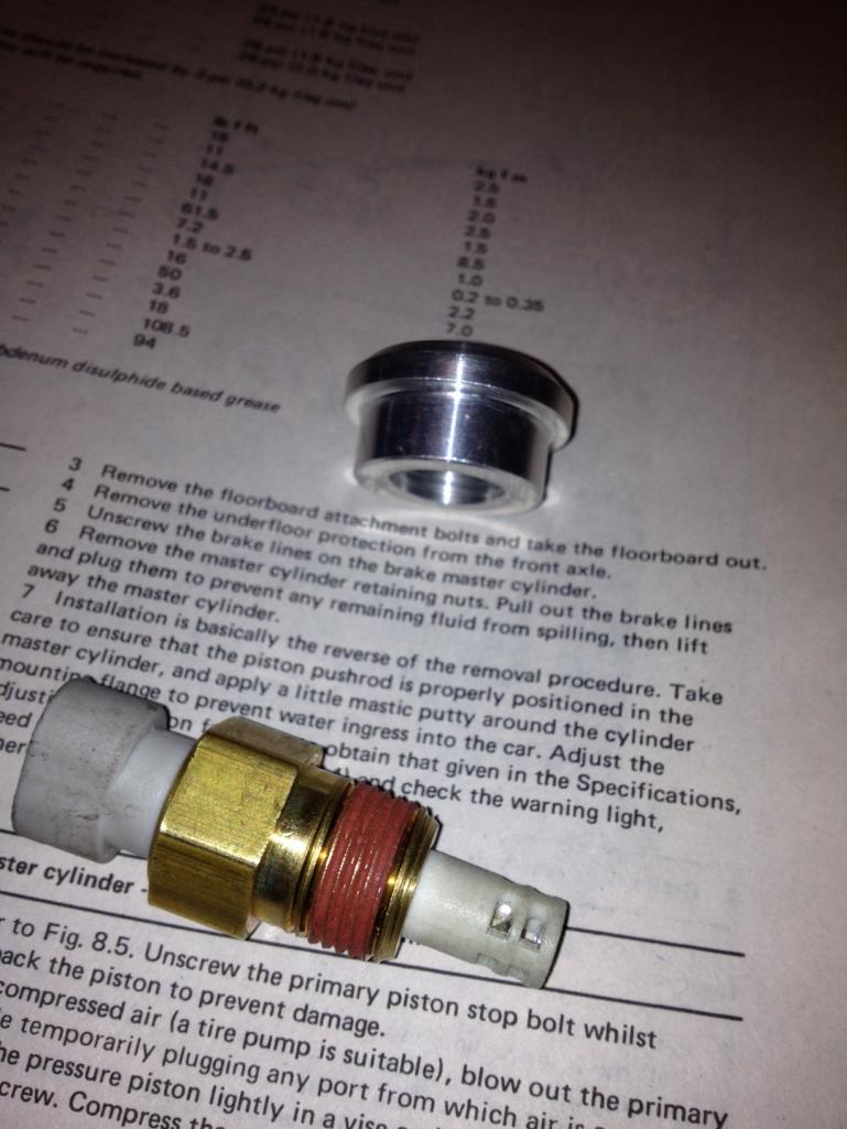 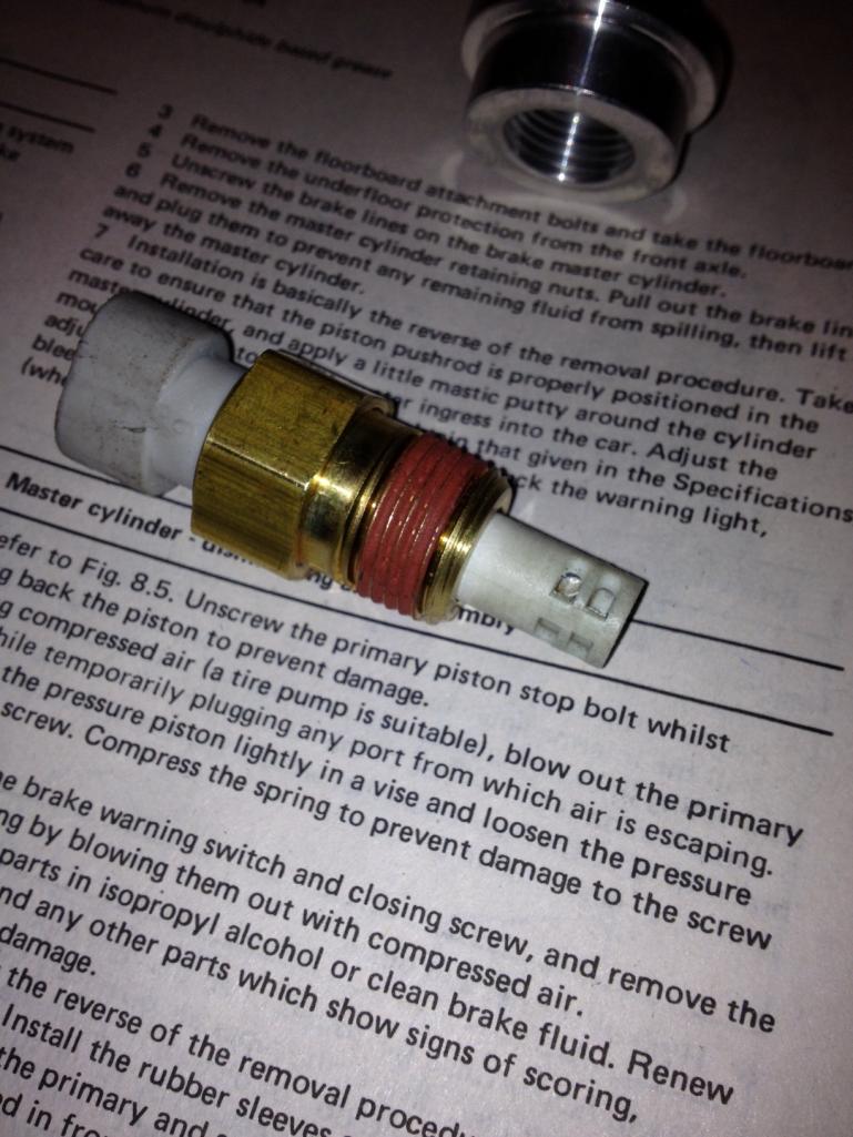
|
|
|
|
| falconfp2001 |
Apr 3 2012, 07:37 PM
Post
#54
|
|
Pancho Pantera Group: Members Posts: 451 Joined: 5-December 10 From: Downey, CA Member No.: 12,456 Region Association: Southwest Region |
QUOTE(JamesM @ Mar 27 2012, 11:54 AM) QUOTE(falconfp2001 @ Mar 26 2012, 10:02 PM) Next Picture. I tested the TPS and the wiring is as follows. Black = +5v Reference Yellow = Sensor return Brown = Ground (like all German autos) All of the wires tested perfectly when I hooked up to my multimeter. I stripped the shield all the way back and took off the boot without ripping it. I'll look for a pin tool tomorrow to take out the pins and re crimp the connections to a paired shielded cable and also the common ground. before soldering to make permanent. Next project for this plenum is to cut off the Temp Sensor and drill for mounting the GM open element style sensor. I purchased a flanged bung so It should mount fairly easy. Another thought on this. If you are going to chage the sensor to the GM one you might want to leave the stock sensor in place and mount the GM sensor somewhere that is more directly in the airflow, like the air cleaner snorkle. the 1.7 places the sensor in a good place right after the TB but the 2.0 location is sort of tucked up out of the way. I was thinking of keeping the old sensor in place just so I could go back to stock sensors if needed but then I thought, why not go all in. I drilled out the old mount and then inserted a bung to mount the new sensor. it actually seems to locate the Sensor into the airstream better than the old sensor. I'll post Pics later. |
|
|
|
| falconfp2001 |
Apr 3 2012, 07:42 PM
Post
#55
|
|
Pancho Pantera Group: Members Posts: 451 Joined: 5-December 10 From: Downey, CA Member No.: 12,456 Region Association: Southwest Region |
Over the weekend I was making my wiring harness while mocking everything up on my spare engine. I noticed while test fitting the new ring style CHT that the spark plugs are inset into the heads and the ring CHT thermistor is positioned to close to the ring to allow it to be bent without damaging the sensor.
Option B, drill out old CHT and make my own. Just have to figure out how to get it on without taking off the tin. I also finished cutting the intake rails to fit with a 2.0L plenum |
|
|
|
| falconfp2001 |
Apr 3 2012, 07:56 PM
Post
#56
|
|
Pancho Pantera Group: Members Posts: 451 Joined: 5-December 10 From: Downey, CA Member No.: 12,456 Region Association: Southwest Region |
Here is the start of my fitment.
Picture 1 shows the 2.0 Plenum Picture 2 shows another angle. what you can not see clearly (sorry about that) is that the intake runners have to be off set. On the 1.7L plenum, the runners for cylinder 3 and 4 are angled so the runners can be directly even. So, what was I to do. Attached thumbnail(s) 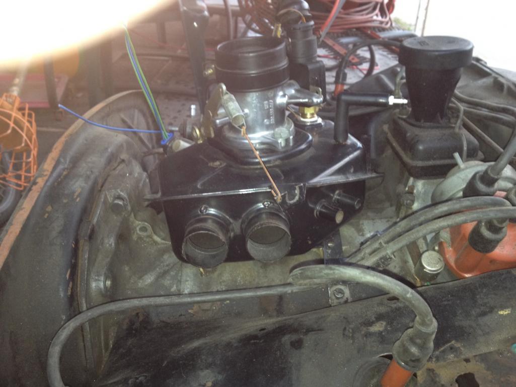 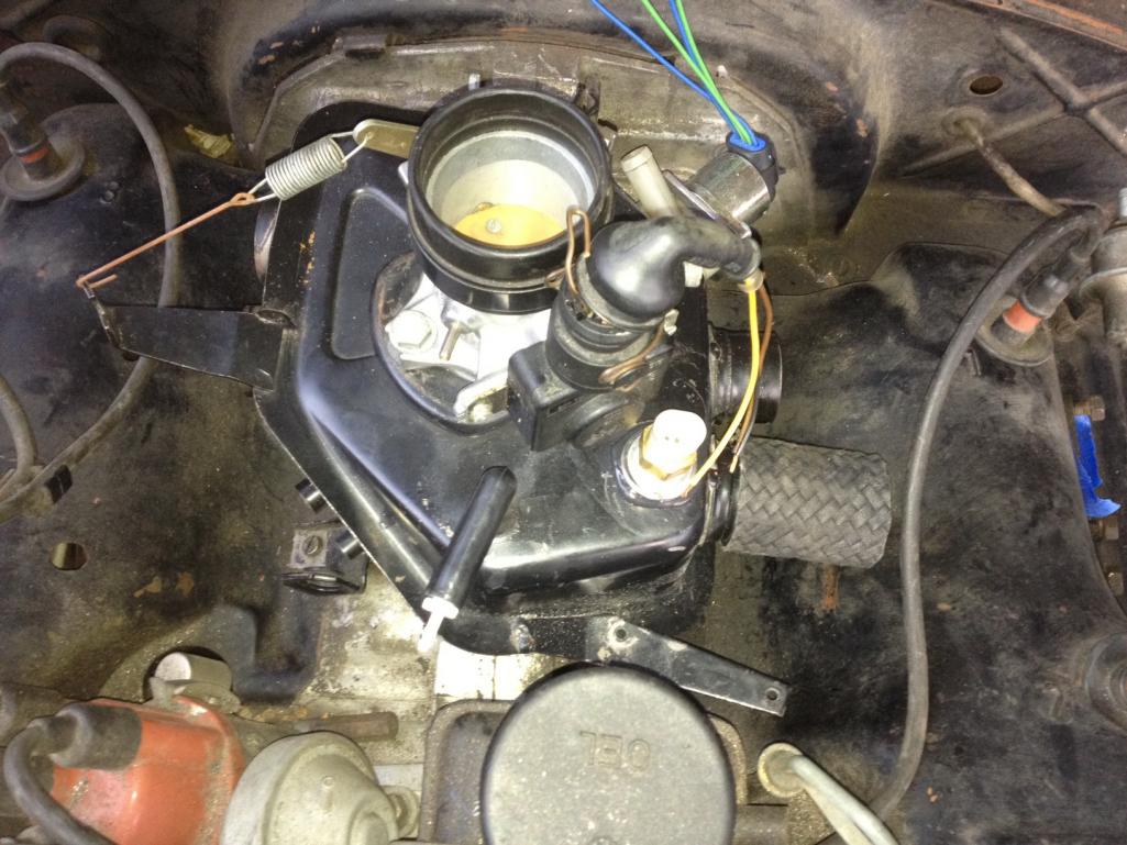
|
|
|
|
| falconfp2001 |
Apr 3 2012, 07:59 PM
Post
#57
|
|
Pancho Pantera Group: Members Posts: 451 Joined: 5-December 10 From: Downey, CA Member No.: 12,456 Region Association: Southwest Region |
I took a spare set of runners I had and matched up two drivers side runners, marked my cuts and trimmed about 2.5 inches off both. Trimmed the tabs that hold the plug wires, sanded cleaned and painted. They don't fit perfect but all I have to do is get them on and then use hose clamps for the rest. They line up very close and look good.
Attached thumbnail(s) 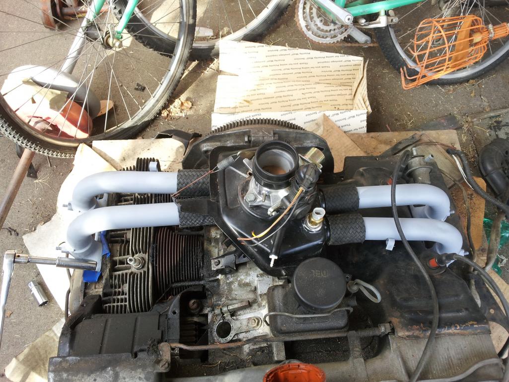
|
|
|
|
| falconfp2001 |
Apr 3 2012, 08:02 PM
Post
#58
|
|
Pancho Pantera Group: Members Posts: 451 Joined: 5-December 10 From: Downey, CA Member No.: 12,456 Region Association: Southwest Region |
QUOTE(falconfp2001 @ Apr 3 2012, 06:59 PM) I took a spare set of runners I had and matched up two drivers side runners, marked my cuts and trimmed about 2.5 inches off both. Trimmed the tabs that hold the plug wires, sanded cleaned and painted. They don't fit perfect but all I have to do is get them on and then use hose clamps for the rest. They line up very close and look good. Now since I finished my wiring harness last night, this weekend is plug and play time. |
|
|
|
| falconfp2001 |
Apr 3 2012, 11:12 PM
Post
#59
|
|
Pancho Pantera Group: Members Posts: 451 Joined: 5-December 10 From: Downey, CA Member No.: 12,456 Region Association: Southwest Region |
Here is a picture of the CHT I'm using. I drilled out an extra stock CHT I had and then used a silicon coated thermistor with some epoxy to install it. used some heat shrink to insulate the terminal ends just a little, soldered a shielded paired cable. Did a staggered crimp of some spade connections at the opposite end of the cable and bazinga. Don't know if I can install without removing tins until this weekend. I bought a cheap extended 13mm socket and notched it so I can use it for just that but I think I may have to remove3 tin so I don't cut the cable. I tested it at 40F, room temp 68F and 180F and it works great. I bought the thermistor on Amazon but you can find them most industrial electrical web sites. there are just so many sizes applications, blaa blaa blaa. Size and Ohms is what matters. The higher the Ohms the more discreet reading you will get but you have to compare that with reaction time to temp change. Again, bla bla bla.
Attached thumbnail(s) 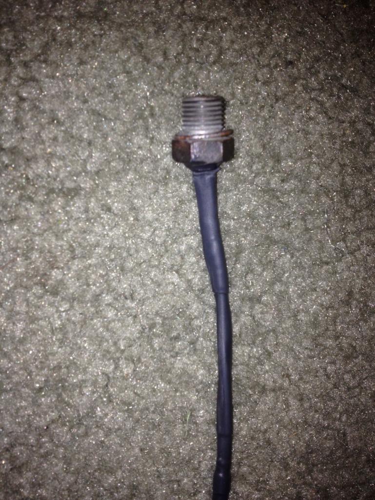
|
|
|
|
| falconfp2001 |
Apr 4 2012, 06:18 PM
Post
#60
|
|
Pancho Pantera Group: Members Posts: 451 Joined: 5-December 10 From: Downey, CA Member No.: 12,456 Region Association: Southwest Region |
Got the main mockup done and the Wire Harness built. Here are some picks of the intake with air filter housing.
You can see the End of my Connections for the IAT and the TPS. Third pic shows where I pull the MAP vacuum from. I like how it looks much cleaner than the 1.7 intake. Easier to access the TPS and all other sensors. Even the throttle cable is easier to get at with this setup. Attached thumbnail(s) 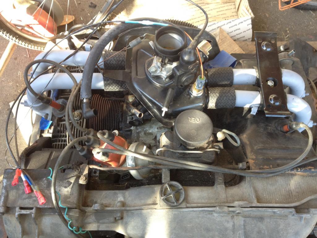 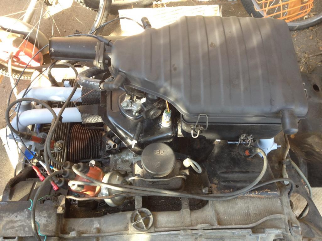 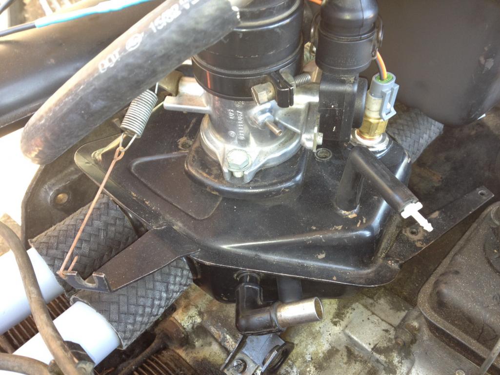
|
|
|
|
|
1 User(s) are reading this topic (1 Guests and 0 Anonymous Users)
0 Members:

|
Lo-Fi Version | Time is now: 4th June 2024 - 11:31 AM |
Invision Power Board
v9.1.4 © 2024 IPS, Inc.