|
|
|
Porsche, and the Porsche crest are registered trademarks of Dr. Ing. h.c. F. Porsche AG.
This site is not affiliated with Porsche in any way. Its only purpose is to provide an online forum for car enthusiasts. All other trademarks are property of their respective owners. |
|
|

  |

| Dtjaden |
 Sep 18 2013, 02:42 PM Sep 18 2013, 02:42 PM
Post
#161
|
|
Member  Group: Members Posts: 232 Joined: 25-May 13 From: Morgan Hill, CA Member No.: 15,915 Region Association: Northern California |
Here are some options from Grainger:
http://www.grainger.com/Grainger/wwg/searc...mp;N=4293734508 Note that there are different tools for insulated and bare terminals. |
   |

 
|
| 76-914 |
Sep 18 2013, 08:21 PM
Post
#162
|
|
Repeat Offender & Resident Subaru Antagonist Group: Members Posts: 13,905 Joined: 23-January 09 From: Temecula, CA Member No.: 9,964 Region Association: Southern California |
Thanks, I ordered a Greenlee tonight. $56.00 w/ tx/shpg. Not bad. (IMG:style_emoticons/default/biggrin.gif) Everything I've done on the harness thus far was soldered so I ask; do you guy's use di-electric grease on crimp joints?
|
|
|
|
| 904svo |
Sep 18 2013, 08:56 PM
Post
#163
|
|
904SVO Group: Members Posts: 1,129 Joined: 17-November 05 From: Woodstock,Georgia Member No.: 5,146 |
QUOTE(76-914 @ Sep 18 2013, 06:21 PM)  Thanks, I ordered a Greenlee tonight. $56.00 w/ tx/shpg. Not bad. (IMG:style_emoticons/default/biggrin.gif) Everything I've done on the harness thus far was soldered so I ask; do you guy's use di-electric grease on crimp joints? Not required if in a dry environment. |
|
|
|
| 76-914 |
Nov 8 2013, 10:12 AM
Post
#164
|
|
Repeat Offender & Resident Subaru Antagonist Group: Members Posts: 13,905 Joined: 23-January 09 From: Temecula, CA Member No.: 9,964 Region Association: Southern California |
I'm back after it after a 5 week hiatus. I thought that f*&$#ing bug was going to kill me and my whining damn near killed my wife. (IMG:style_emoticons/default/laugh.gif) Let's see, where did I leave off? The wiring (IMG:style_emoticons/default/barf.gif) . I have most of the new wiring done and installed though not tested or properly installed in the looms. I was glad that I saved the Suby wiring grommets as they came in handy. I'll post some pic's of this later. I pulled the drive train to replace some hoses and other odds n ends before reinstalling for one of the last times, I hope!
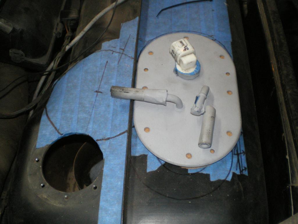
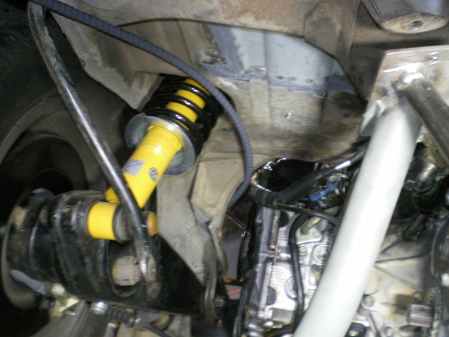
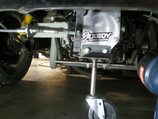
While out I thought I'd try removing the power steering pump which isn't needed. 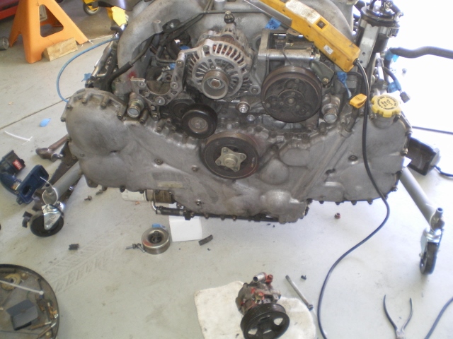 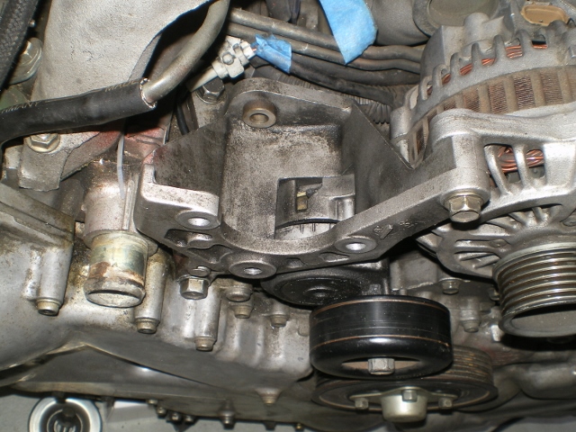 First attempt was with a 47" belt which was too loose. I used this pic with the PS pump still installed to show how much the geometry changes as related to the tensioner. When the belt went around the large pulley of the pump the tensioner was effective but as you see in the final pics it is less effective. I ended up using a 46.5" belt which was Hell to install. Very tight to slip on even with the tensioner relaxed. I think it is tight enough but time will tell. I may have to re-install the pump just for the use of that pully. This is the 47" belt. A little too loose. 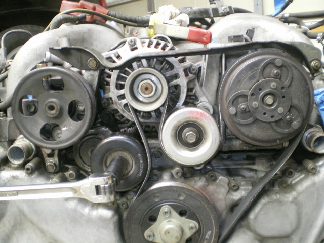 The 46.5" belt installed 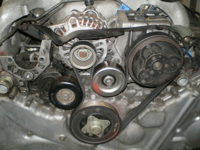 I could use a little help here. Any Suby guys here that can identify these fuel hoses? I can't seem to locate that info in the manuals. (IMG:style_emoticons/default/slap.gif) What are #1,2 & 3? Is #4 a filter. Are any of these not used? I assume that gas enters the canister #4 to the fuel rail via #1. #2 is the return? #3 fuel vapor???? 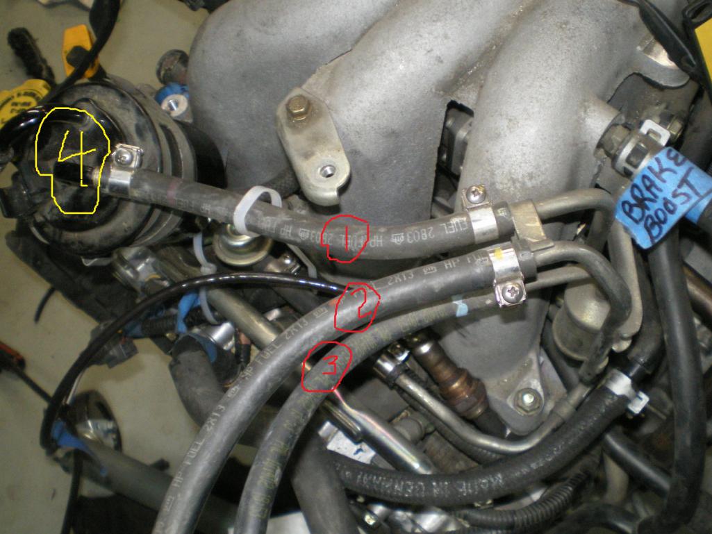 |
|
|
|
| Chris H. |
Nov 8 2013, 12:45 PM
Post
#165
|
|
Senior Member Group: Members Posts: 4,090 Joined: 2-January 03 From: Chicago 'burbs Member No.: 73 Region Association: Upper MidWest |
Welcome back Kent! Glad you're well again.
The big cylinder thingy to the left labeled #4 is your fuel filter. Replace it when you do your next parts order. They are cheap. The fuel flow is - out of the tank and into the fuel filter first, so that would mean that #1 is most likely your "line in". Since #2 is the exact same hose type that is probably your "line out" return line back to the tank exactly like the FI teener setup. Check the manual again for #3. Probably a vapor thing but just make sure it's not pressurized...most likely goes to a canister or back through the manifold or something. But make suuuure. Be careful and also make sure your hose clamps are very tight....we're going to 60 psi now! Yeeehaaaaa! |
|
|
|
| strawman |
Nov 10 2013, 10:27 PM
Post
#166
|
|
Senior Member Group: Members Posts: 891 Joined: 25-January 08 From: Los Osos, CA Member No.: 8,624 Region Association: Central California |
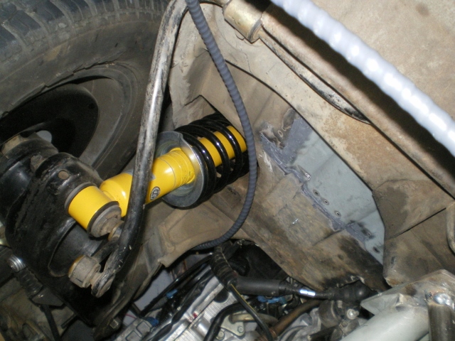
QUOTE(76-914 @ Nov 8 2013, 08:12 AM) I could use a little help here. Any Suby guys here that can identify these fuel hoses? I can't seem to locate that info in the manuals. (IMG:style_emoticons/default/slap.gif) What are #1,2 & 3? Is #4 a filter. Are any of these not used? I assume that gas enters the canister #4 to the fuel rail via #1. #2 is the return? #3 fuel vapor???? This topic made we wince... my turbo Suby Teener project was stalled for a couple of weeks until I figured out that I mixed up the inlet and return hoses. Once I figured it out, my car purred! I agree with Chris H. that #1 is the inlet, #2 is the outlet, and #3 is a vapor breather line. Well, at least that is what mine looks like (see the pic below) -- the inlet is the one on the left and the outlet is the one on the right, underneath the air-to-water intercooler. What originally tricked me was that I assumed the inlet pipe should feed the fuel pressure regulator; in actuality, the pipe coming out of the fuel pressure regulator feeds back to the fuel tank. Hope this makes sense. 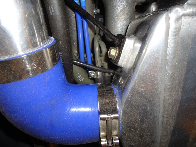 |
|
|
|
| 76-914 |
Nov 11 2013, 06:28 PM
Post
#167
|
|
Repeat Offender & Resident Subaru Antagonist Group: Members Posts: 13,905 Joined: 23-January 09 From: Temecula, CA Member No.: 9,964 Region Association: Southern California |
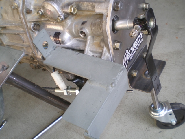
Thanks Chris & Geoff, Wasn't sure and damned if I can find that in print, yet..... (IMG:style_emoticons/default/blink.gif) Saturday I rolled the drivetrain back into position to mark where the truck gets cut and to begin the shifter fabrication. I think I'm going to just say "stuff" from now on. It's easier to spell. I'm using the MR2 shifter. I'm not sure how it was mounted in the Toyo but it won't set flush on any flat surface so it needed to be raised about 1.5 - 2". In keeping with my CSOB ways all the metal was from pile o' (IMG:style_emoticons/default/stromberg.gif) .
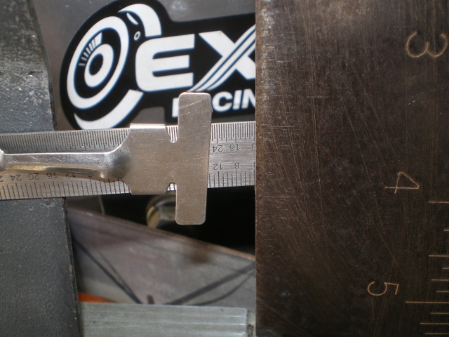
The 1-2, 3-4, 5-R gates are controlled by the rotation of the shaft, An 1/8" flat lever was drilled & welded onto a piece of 5/8" tube, .095 IIRC. My shifter has appx 30mm travel or 15mm 1/2 travel. Borrowing "heavily" from DB Cooper's build I began to search for the sweet spot in the lever. I want to have about 13-14mm between the gates which is slightly less than the maximum travel of the shifter. I may end up adding some limiters o the shifter itself, later. (IMG:style_emoticons/default/confused24.gif) This little gizmo allowed me to measure the travel and locate the attach point of the cable. Edit : Opps, hit the wrong button. Will add the rest of this on the next page Attached image(s) 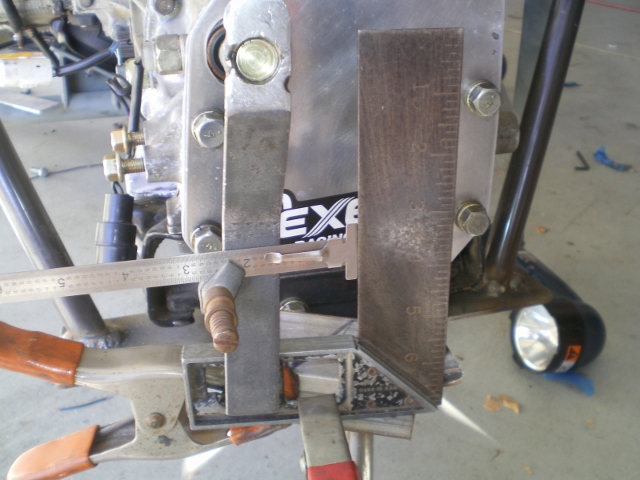 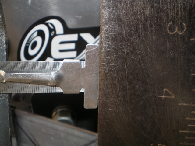
|
|
|
|
| 76-914 |
Nov 11 2013, 07:18 PM
Post
#168
|
|
Repeat Offender & Resident Subaru Antagonist Group: Members Posts: 13,905 Joined: 23-January 09 From: Temecula, CA Member No.: 9,964 Region Association: Southern California |
Round 2. (IMG:style_emoticons/default/dry.gif)
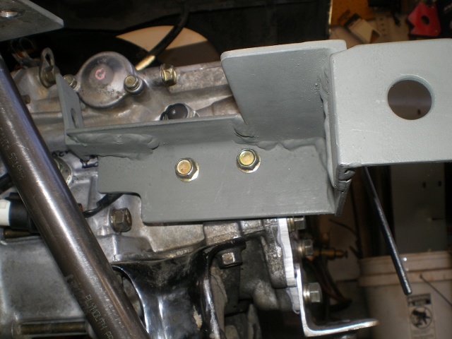
 These guy's were of no help  This was the starting point for mounting the shifter. 2ea.- 5.5" pieces of 1/8 x 2" angle. These were drilled to match the existing tapped holes for the old shifter. A basic "T" configuration. KISS. The back 2 bolts are symbolic. One 13mm German/one 12mm Nippon; same thread. (IMG:style_emoticons/default/beer.gif) The blue tape has center line marks of the old shifter. I set mine back a few inch's to accommodate me. 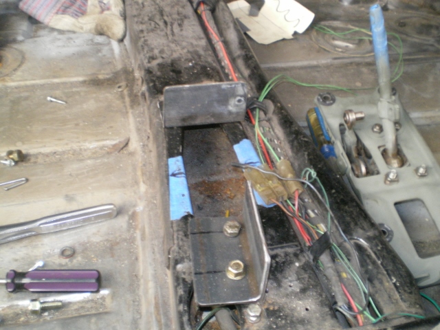 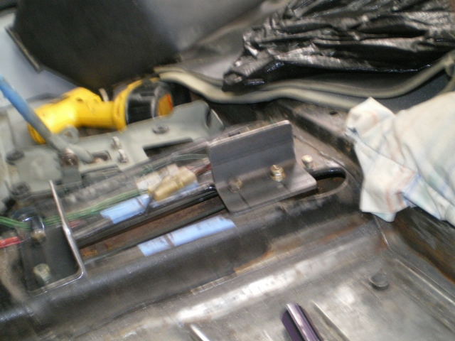 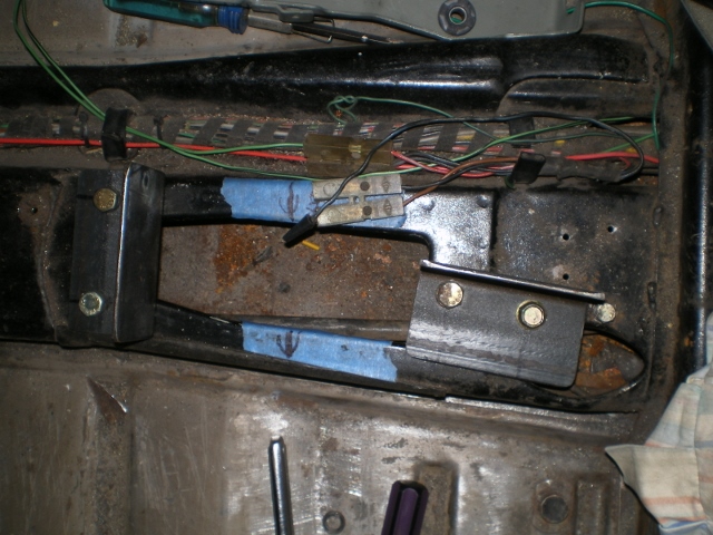 A 9.5" x 5.5" x 1/8" plate was cut out to allow for shifter recess then placed on the angle and tacked into place. I''ll weld it up later. 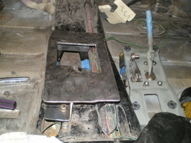 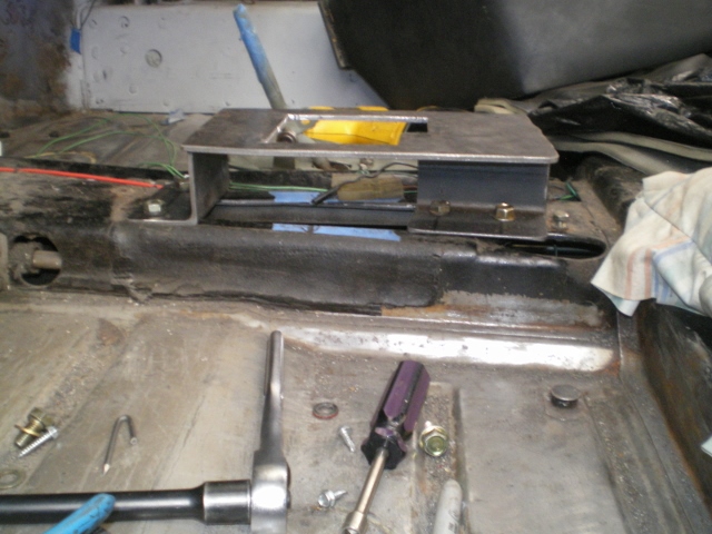 A quick test fit to be sure the console fits. I'll make another piece of burled aluminum to cover this area as it was before. 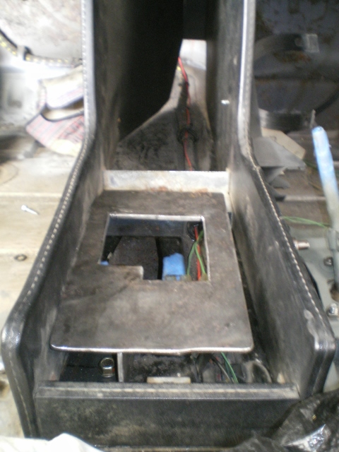 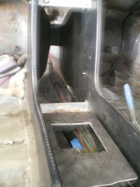 Mounted the shifter. Look close you will see the felt tip measurements on the side of the shifter. As mentioned earlier, the piece on the left side moves for and aft as the stick is moved left and right. I know. It's freeking magic but it does. (IMG:style_emoticons/default/blink.gif) This movement is 15mm & 15mm. The eyelet on the shift rod is the one that controls movement between 1&2 or 3&4 or 5&R. Or the in-out action of the rod on the transmission. The travel here is 60mm or twice what's needed at the tranny so I will most likely lower the eyelet appx 13mm. 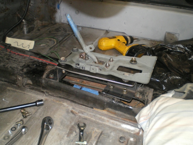 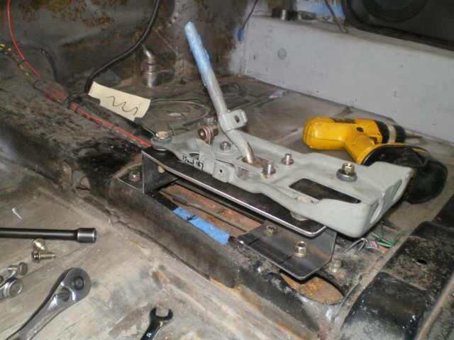 Now it's point "A" to point "B" measurement time. Stole this idea from Bob. Looks like 6.5' and 7.5'. 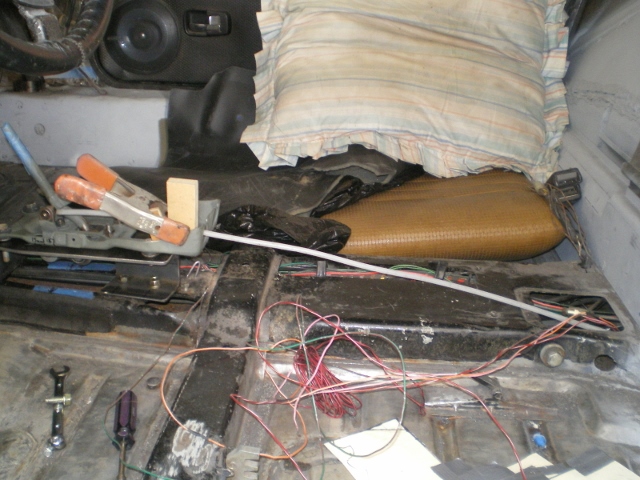 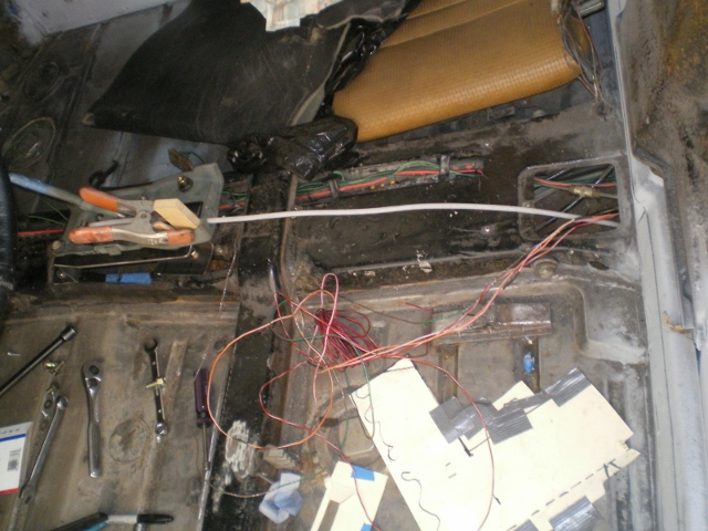 |
|
|
|
| 76-914 |
Nov 14 2013, 07:54 PM
Post
#169
|
|
Repeat Offender & Resident Subaru Antagonist Group: Members Posts: 13,905 Joined: 23-January 09 From: Temecula, CA Member No.: 9,964 Region Association: Southern California |
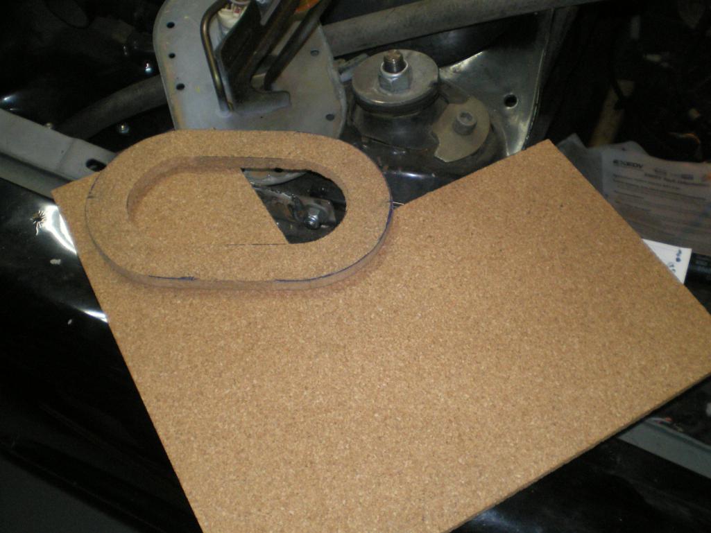
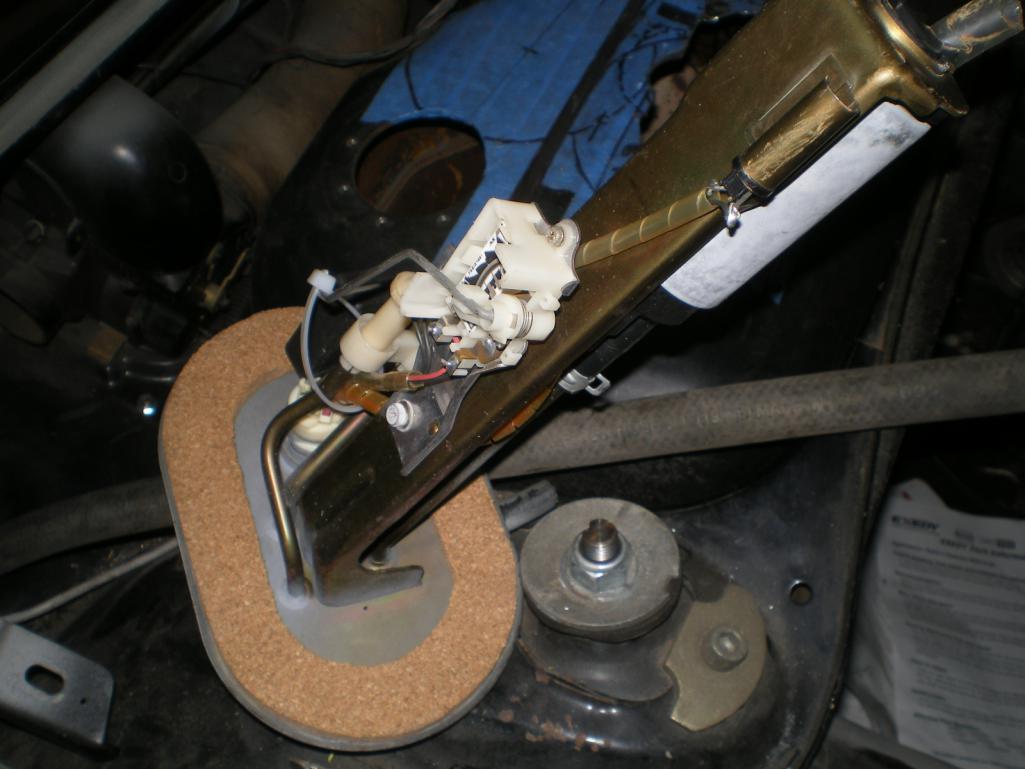
While I'm waiting for the cables to come in I jumped back to the tank to make this gasket for the Suby fuel pump. The tank isn't so flat at one end of the cut out so I cut this cork gasket from a 3/8" sheet. Now I need to decide whether to use rivenuts or plate nuts for the bolts. (IMG:style_emoticons/default/idea.gif)
   |
|
|
|
| Chris H. |
Nov 14 2013, 09:38 PM
Post
#170
|
|
Senior Member Group: Members Posts: 4,090 Joined: 2-January 03 From: Chicago 'burbs Member No.: 73 Region Association: Upper MidWest |
Nice work Kent! Looks like the cable shifter is a lot more fine tuning than I imagined...hoping Ian will get one cooking soon. Getting organized for another blast of work on mine. Been really cold out here.
|
|
|
|
| Chris H. |
Nov 15 2013, 07:23 AM
Post
#171
|
|
Senior Member Group: Members Posts: 4,090 Joined: 2-January 03 From: Chicago 'burbs Member No.: 73 Region Association: Upper MidWest |
Hey BTW not sure if this will help at all but the cableshift.com website has instructions for adjusting their cable shift setups. Their Subie setup is different than the way we plan to do it but it might help you anyway:
Setup Instructions There are several other cable shift setups on there too. |
|
|
|
| 76-914 |
Nov 21 2013, 02:26 PM
Post
#172
|
|
Repeat Offender & Resident Subaru Antagonist Group: Members Posts: 13,905 Joined: 23-January 09 From: Temecula, CA Member No.: 9,964 Region Association: Southern California |
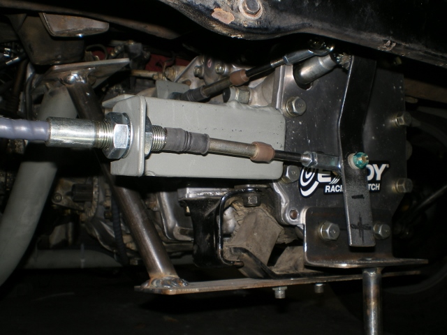
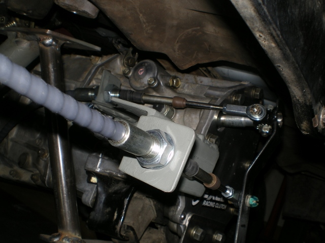
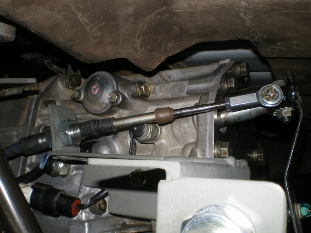
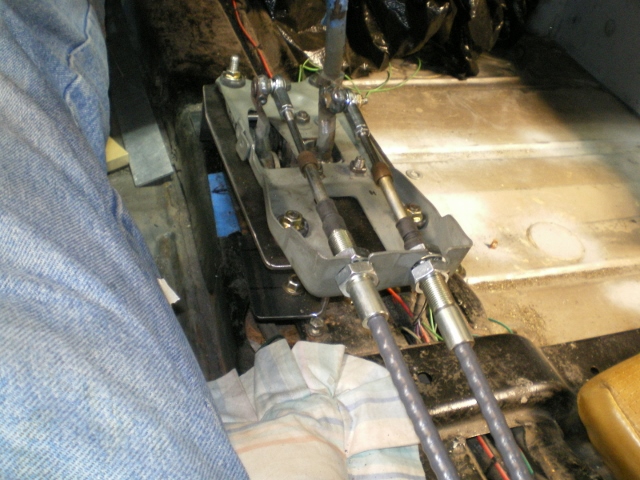
The cables arrived and I couldn't wait to hook 'em up. Yes, I think I could have shortened them by 6" or so but I took the safe route. The first thing was to get the MR2 shifter to accept the 1/4" cables. As you can see in the first pic, this peg is 10mm in diameter; too large for the 1/4" hiem joint. And the other side looks like it was set up for some type of clevis joint. I thought the clevis might intro some unneeded slop so I welded a 1/4" shoulder bolt thru this opening as well.
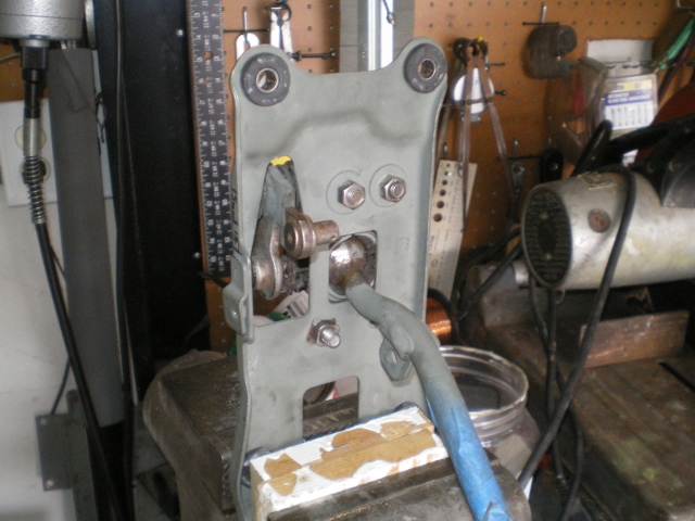 So I ground it off flush and welded a 1/4" shoulder bolt in it's place. 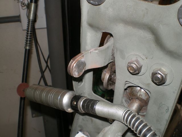 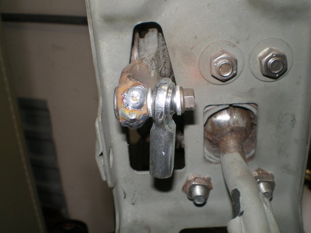 Once I began to move the shifter thru it's pattern I found a clearance issue so I had to grind down an overblown factory weld. 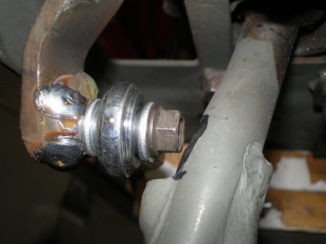 Then the head of this bolt needed to be ground down a tad. Now everything moves about freely. 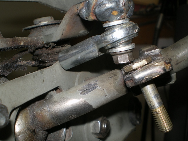 The cables attached in the cabin......It was necessary to remove the plastic bushing on the firewall where the shift rod had passed thru. Odd that the bushing was a Royal PITA to install yet popped out quite easily. (IMG:style_emoticons/default/WTF.gif) Once removed it was possible to fit the cables thru that opening after removing the nuts and washers. I'll get pic's from the rear in the next post. I need to find the engine mount bolts that I put somewhere when I was sick. (IMG:style_emoticons/default/headbang.gif) 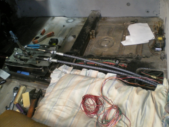 So while I look for the bolts for the motor mount I moved onto finish the fuel pump install. But before I can install the pump I need to level out the tanks surface. The tank offsets just a tad next to the flanged area where the tank halves join together. This is a 1.25" x 15" piece of square stock that is clamped here. You can see the hump if you look closely. 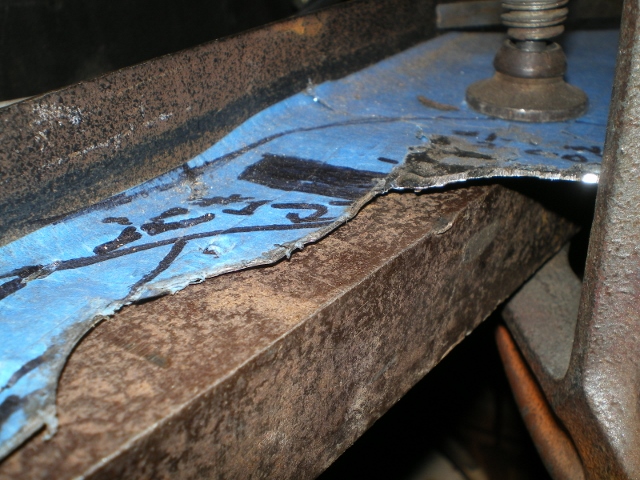 With a bit of hammering against the stock piece it flattened out well. 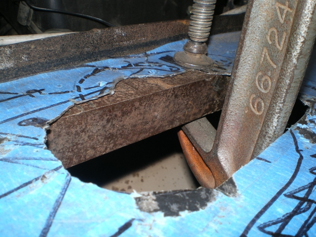 Now the pilot holes are enlarged to accept the rivenuts. 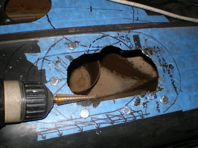 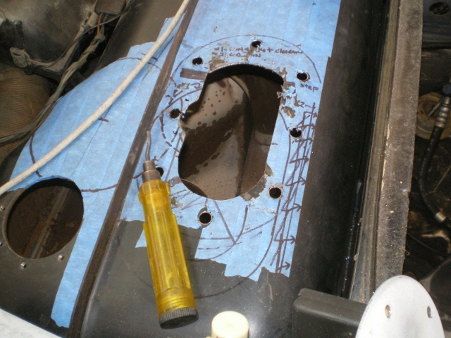 Then a final clean before the Rivenuts & JB Weld. 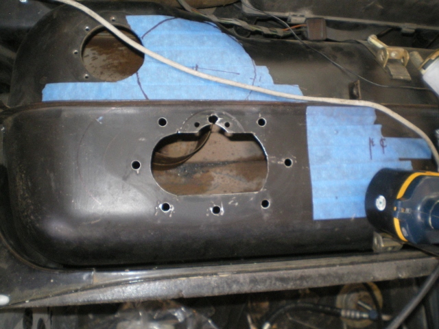 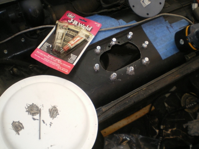 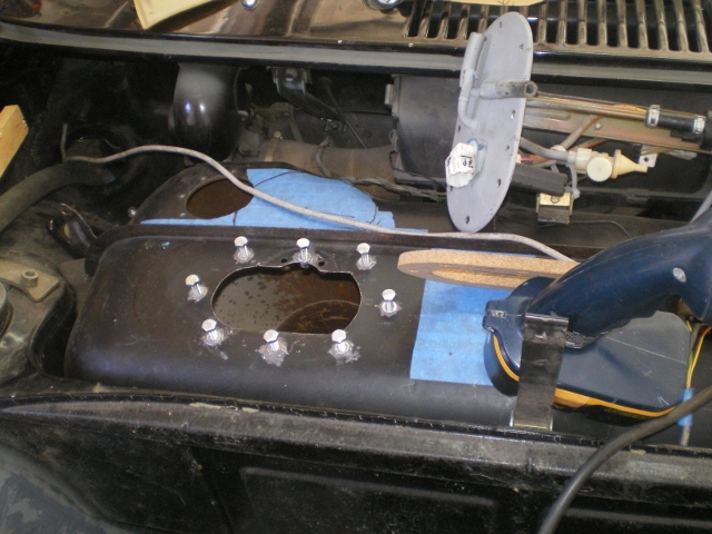 Let the JB Weld set up overnight then attached the pump housing. It fit! (IMG:style_emoticons/default/piratenanner.gif) 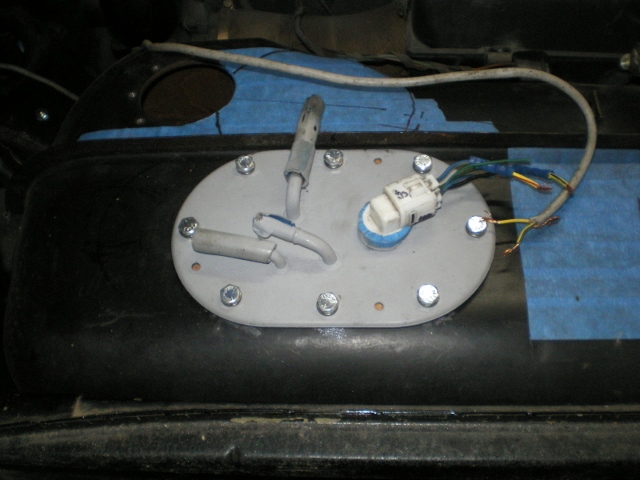 |
|
|
|
| strawman |
Nov 22 2013, 05:39 PM
Post
#173
|
|
Senior Member Group: Members Posts: 891 Joined: 25-January 08 From: Los Osos, CA Member No.: 8,624 Region Association: Central California |
Before you weld up the shifter mounting base, you might want to consider raising it. I had to mock up a system to raise mine a few inches and move it back so that I didn't have to lean over to reach it. I'd suggest mounting the driver seat and making sure he ergonomics are correct before finalizing everything, since the first-gen Toyota MR2 shifter is short compared to the stock 914 shifter. I still need to weld up a final mount system.
Be sure you make vroom-vroom noises while checking it all out... |
|
|
|
| 76-914 |
Nov 23 2013, 08:57 AM
Post
#174
|
|
Repeat Offender & Resident Subaru Antagonist Group: Members Posts: 13,905 Joined: 23-January 09 From: Temecula, CA Member No.: 9,964 Region Association: Southern California |
Good point, Geoff. I did set the shifter back a few inches and centered it within the console but I'd better put the seat in, as you've suggested, for the real world scenario. Thx!
|
|
|
|
| 76-914 |
Nov 23 2013, 09:48 PM
Post
#175
|
|
Repeat Offender & Resident Subaru Antagonist Group: Members Posts: 13,905 Joined: 23-January 09 From: Temecula, CA Member No.: 9,964 Region Association: Southern California |
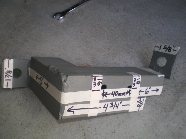
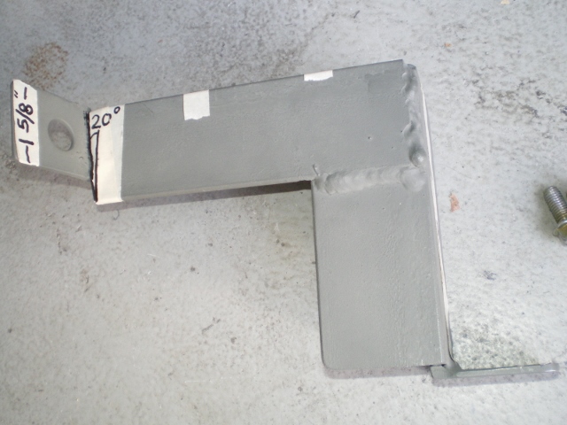
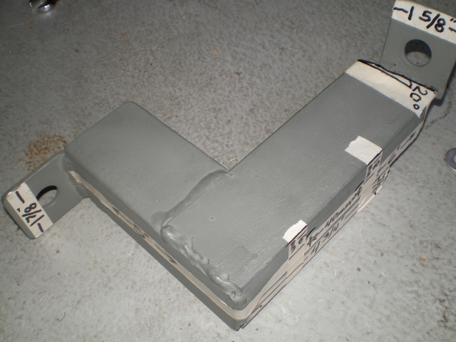
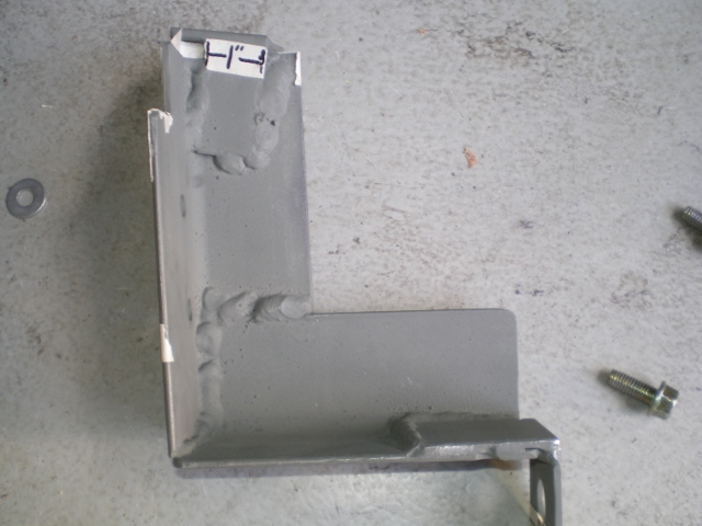
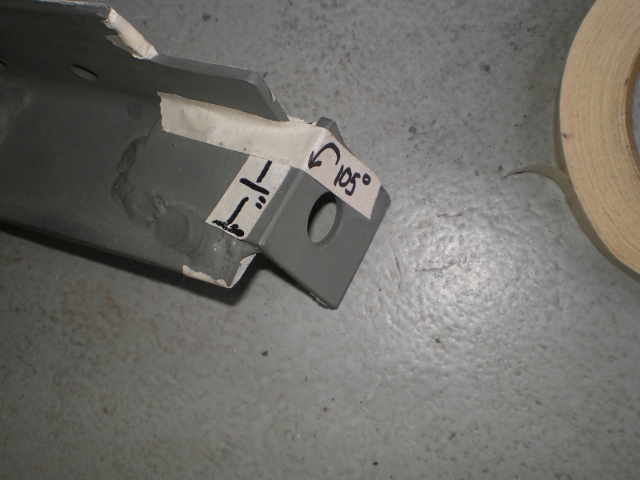
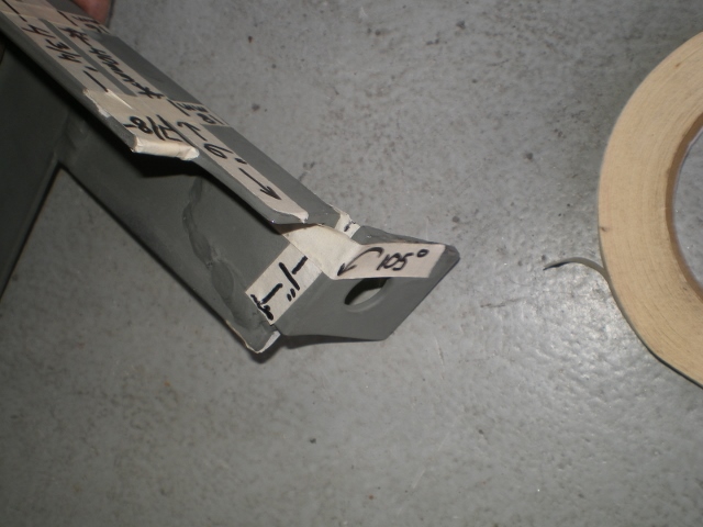
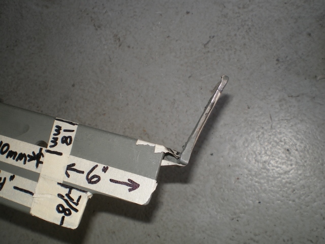
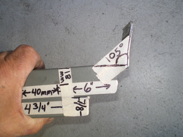
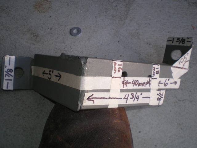
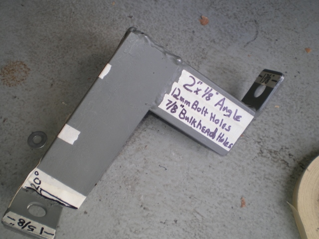
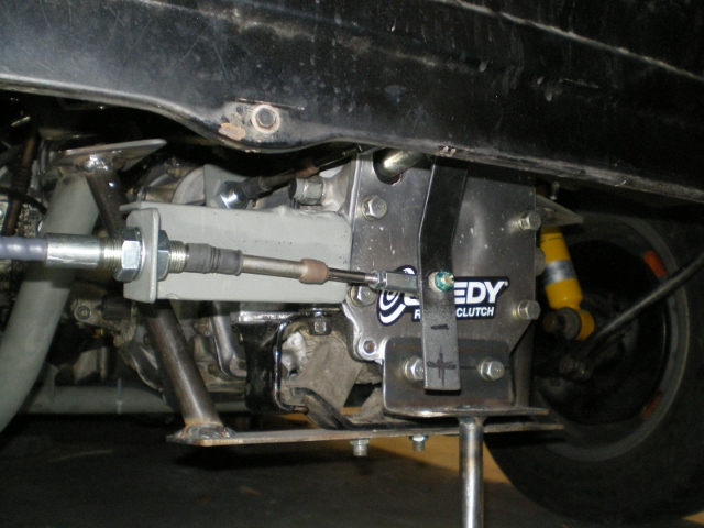
I was able to finish up with the shifter fab today so I thought I'd throw out a few dimensions here 'n there for others. You will need one 15" piece of 2x2 angle 1/8" thick. Cut one piece 6", one piece 5", one piece 1 7/8", one piece 1 5/8". Pieces will not fit flush against one another because of the filet or curvature unless you grind off about 1/8" where the pieces lap together. There are two 12mm holes drilled to attach this to the transmission. They are drilled 40mm apart c/c and staggered 2mm as shown. The 6" piece gets a 7/8"x1 1/4" section removed for clearance of a trans bolt. The 1 5/8" piece is placed in a vice and squeezed to open 15 degrees then reduced to 1" wide on it's other side. This is necessary to allow for the 20 degree angle while keeping the bulkhead in line and centered. I haven't cut the levered piece to it's final length because I want to play with some different throws but I pretty sure it will stay where it is. It shifts like a brand new car and I can't wait to drive this new set up. It still needs to be tidied up, painted, etc. Anyway I'm going to throw a bunch of pics at you. It's pretty self explanatory but ask if you have any ???
                     |
|
|
|
| rick 918-S |
Nov 23 2013, 10:30 PM
Post
#176
|
|
Hey nice rack! -Celette Group: Members Posts: 21,291 Joined: 30-December 02 From: Now in Superior WI Member No.: 43 Region Association: Northstar Region |
Nice Kent! What is the HP of that 6? I'm working on an idea for a mid-engine shop truck and was thinking a Sub 6 would be the answer. I would need enough hp to pull a trailer. (my trailer with a 914 on it)
|
|
|
|
| euro911 |
Nov 23 2013, 10:58 PM
Post
#177
|
|
Retired & living the dream. God help me if I wake up! Group: Members Posts: 8,937 Joined: 2-December 06 From: So.Cal. & No.AZ (USA) Member No.: 7,300 Region Association: Southern California |
Industrious bugger, ain't ya?
Looks nice. Neat 'wheelie bar' too (IMG:style_emoticons/default/laugh.gif)  |
|
|
|
| DBCooper |
Nov 23 2013, 11:11 PM
Post
#178
|
|
14's in the 13's with ATTITUDE Group: Members Posts: 3,079 Joined: 25-August 04 From: Dazed and Confused Member No.: 2,618 Region Association: Northern California |
I'm happy you were able to get it worked out, since I still can't get down on the ground. Well, I could get down but probably not back up. At the end of the day it's pretty simple, isn't it? It makes all the difference in the world in how the car drives.
I need to take some photos of the way my shifter's mounted, it's a little different than your setup. Well done. |
|
|
|
| Chris H. |
Nov 24 2013, 12:43 PM
Post
#179
|
|
Senior Member Group: Members Posts: 4,090 Joined: 2-January 03 From: Chicago 'burbs Member No.: 73 Region Association: Upper MidWest |
Whoa....Kent...that's above and beyond.... (IMG:style_emoticons/default/pray.gif) Thanks man.
Even I could do that using your instructions. Hoping to have some time over the holidays to get serious about the project again. Hey were both cables a little long? Actually hoping so because I want to use the Honda shifter and it might be a little different. Nice work!!!!!! (IMG:style_emoticons/default/first.gif) |
|
|
|
| 76-914 |
Nov 24 2013, 12:52 PM
Post
#180
|
|
Repeat Offender & Resident Subaru Antagonist Group: Members Posts: 13,905 Joined: 23-January 09 From: Temecula, CA Member No.: 9,964 Region Association: Southern California |
QUOTE(rick 918-S @ Nov 23 2013, 08:30 PM) Nice Kent! What is the HP of that 6? I'm working on an idea for a mid-engine shop truck and was thinking a Sub 6 would be the answer. I would need enough hp to pull a trailer. (my trailer with a 914 on it) IIRC, 230hp Rick. The 3.3's are cheaper, longer, heavier and have a few more horses. If you go 2004 or newer you'll be "fly by wire", +30 hp, ACAV. Gets complicated. QUOTE(euro911 @ Nov 23 2013, 08:58 PM) Industrious bugger, ain't ya? Looks nice. Neat 'wheelie bar' too (IMG:style_emoticons/default/laugh.gif) You know, not really. This was the easiest mod I've done to this car, yet! As pristine as my '76's shifter is....it is a turd compared to this cable set up. (IMG:style_emoticons/default/aktion035.gif) QUOTE(DBCooper @ Nov 23 2013, 09:11 PM) I'm happy you were able to get it worked out, since I still can't get down on the ground. Well, I could get down but probably not back up. At the end of the day it's pretty simple, isn't it? It makes all the difference in the world in how the car drives. I need to take some photos of the way my shifters mounted, it's a little different than your setup. Well done. Well thank you DB. Emulation being the sincerest form of flattery. (IMG:style_emoticons/default/biggrin.gif) Or more bluntly; I copied from your build. (IMG:style_emoticons/default/happy11.gif) I didn't have that curved piece and was too lazy to make one. I tried to closely align the cable with travel path of the push rod in the tranny to lessen the cable force. Other than that I stole from your post. Hey DB, do you have back up lights? I noticed that you have the back up and neutral senders looped together. And yes, it is pretty simple in the end. I couldn't wait to rant here about how well it shifted, How precise and crisp it feels. Then I remembered you had already said what I felt. (IMG:style_emoticons/default/thumb3d.gif) You did not exaggerate. |
|
|
|
|
2 User(s) are reading this topic (2 Guests and 0 Anonymous Users)
0 Members:

|
Lo-Fi Version | Time is now: 25th June 2026 - 01:16 AM |
Invision Power Board
v9.1.4 © 2026 IPS, Inc.