|
|
|
Porsche, and the Porsche crest are registered trademarks of Dr. Ing. h.c. F. Porsche AG.
This site is not affiliated with Porsche in any way. Its only purpose is to provide an online forum for car enthusiasts. All other trademarks are property of their respective owners. |
|
|

  |

| AfricanHijinx |
 Feb 27 2014, 12:03 PM Feb 27 2014, 12:03 PM
Post
#261
|
|
Member  Group: Members Posts: 132 Joined: 12-April 11 From: Snohomish WA Member No.: 12,928 Region Association: Pacific Northwest |
what bed liner did you use? I used some duplicolor stuff from the FLAPS and it was garbage it scratched pretty quick
|
   |

 
|
| ruby914 |
Feb 27 2014, 12:35 PM
Post
#262
|
|
Senior Member Group: Members Posts: 720 Joined: 26-April 09 From: Hawthorne, Ca Member No.: 10,305 Region Association: None |
QUOTE(skeates @ Feb 27 2014, 08:45 AM)  QUOTE(76-914 @ Feb 26 2014, 05:27 PM) I think it was Skeates who mentioned he was tired of playing Concentration with himself when describing the wiring. (IMG:style_emoticons/default/av-943.gif) (IMG:style_emoticons/default/lol-2.gif) (IMG:style_emoticons/default/laugh.gif) Very well put. Twas not I who coined that one, but I'll take the credit. (IMG:style_emoticons/default/happy11.gif) Looks like you are making some good progress. I'm particularly interested in seeing how your cooling solution works out as it is much easier to run those smaller diameter hoses. I also went with the 1.25" hose to keep things close to the stock sizes, but it sounds like there may be a significant amount of wiggle room there. Keep up this momentum and you'll be driving before you know it! I think that was Scott Amenson on his MIA 2014 come back. I still have $200 worth of copper that I pulled out of my car. Going to make a wind chime. (IMG:style_emoticons/default/aktion035.gif) I had mine all suspended by rubber. Thought I could get around it. I think it was Porsharu that sent me this PDF? May have saved my butt. I didn't want all my work rotting from within. Attached File(s)  electrolysis.pdf ( 57.49k )
Number of downloads: 263
electrolysis.pdf ( 57.49k )
Number of downloads: 263 |
|
|
|
| rnellums |
Feb 27 2014, 05:11 PM
Post
#263
|
|
Professional Enthusiast Group: Members Posts: 1,673 Joined: 26-November 09 From: Littleton, CO Member No.: 11,072 Region Association: Rocky Mountains |
For my joints, I bout some aluminum extenders off amazon, but the tee required for the EZ30 is what is killing me (one cold return @1.5" but TWO outlets @ 1.25"!)
|
|
|
|
| 76-914 |
Feb 27 2014, 07:43 PM
Post
#264
|
|
Repeat Offender & Resident Subaru Antagonist Group: Members Posts: 13,905 Joined: 23-January 09 From: Temecula, CA Member No.: 9,964 Region Association: Southern California |
QUOTE(CptTripps @ Feb 27 2014, 01:42 AM) Outstanding progress. One quick question though: Which bed liner did you end up using? That's on my list, and I don't want to use what I used last time. Monstaliner. I think it came from JEGS. I traded my "flucks" core welder to my buddy for 2 gallons of this stuff. JEGS gave it to him because they shipped the wrong colour. Win Win. I think this stuff needs to go on thick if you want durability. I did this in the front trunk area for obvious reasons. The pans were just a couple of coats. It will be covered and didn't need to be tough. QUOTE(Chris H. @ Feb 27 2014, 09:24 AM) (IMG:style_emoticons/default/idea.gif) I'm re-thinking what size pipe to run under the car too...was going with 1 1/4 as well but if that isn't necessary I'll go smaller. Much easier to bend the smaller it is (insert easy joke response here....). Chris and other concerned souls: this comes from the horse's, or in this case the KAT's, mouth. Bob (BIGKAT83) was kind enough to share his set up. He is running SS braided lines w/ AN fittings but other than the material choice, the sizes are the same. As I said somewhere back; I don't expect the hose size will be a problem. And if there is a cooling problem I will suspect my choice of routing and additional turns that I added. Bob also twinned the 1.25 into a 3/4 line. This setup has served his 3.3 and 3.0 engines. Just be sure both 1.25 hoses are identical in every respect. IOW, the T should be in the middle and if one side goes 8" turns 90 degrees then 5" the other side should be the same. Helps to balance the flow. Great progress Kent! BTW guys can you coat the inside of that copper with anything that would keep it from reacting/breaking down into the water? Or slow it down enough to make it less of an issue? QUOTE(AfricanHijinx @ Feb 27 2014, 10:03 AM) what bed liner did you use? I used some duplicolor stuff from the FLAPS and it was garbage it scratched pretty quick Hijinx, see above. Capt tripps had the same ??? (IMG:style_emoticons/default/beerchug.gif) QUOTE(ruby914 @ Feb 27 2014, 10:35 AM) QUOTE(skeates @ Feb 27 2014, 08:45 AM) QUOTE(76-914 @ Feb 26 2014, 05:27 PM) I think it was Skeates who mentioned he was tired of playing Concentration with himself when describing the wiring. (IMG:style_emoticons/default/av-943.gif) (IMG:style_emoticons/default/lol-2.gif) (IMG:style_emoticons/default/laugh.gif) Very well put. Twas not I who coined that one, but I'll take the credit. (IMG:style_emoticons/default/happy11.gif) Looks like you are making some good progress. I'm particularly interested in seeing how your cooling solution works out as it is much easier to run those smaller diameter hoses. I also went with the 1.25" hose to keep things close to the stock sizes, but it sounds like there may be a significant amount of wiggle room there. Keep up this momentum and you'll be driving before you know it! I think that was Scott Amenson on his MIA 2014 come back. I still have $200 worth of copper that I pulled out of my car. Going to make a wind chime. (IMG:style_emoticons/default/aktion035.gif) I had mine all suspended by rubber. Thought I could get around it. I think it was Porsharu that sent me this PDF? May have saved my butt. I didn't want all my work rotting from within. That's not the article I was looking for. It's better. Thanks. I think with that info I can avoid loosing a radiator. Hell, it may all come out and go beneath the car like everyone else. (IMG:style_emoticons/default/idea.gif) Radiator new was <$60 so it wouldn't hair lip me if it tanked. I love that the article tells how to test it with your VOM. Did you perform all those tests? Results?? It points out why grounds are so important. The OG Suby harness must have 20 random ground cables that attach to the body in different locations. Hmmmmmmmm. Hey, hey> My fan switch arrived so I can plug that hole in the radiator. (IMG:style_emoticons/default/piratenanner.gif) |
|
|
|
| ruby914 |
Feb 27 2014, 08:45 PM
Post
#265
|
|
Senior Member Group: Members Posts: 720 Joined: 26-April 09 From: Hawthorne, Ca Member No.: 10,305 Region Association: None |
''Radiator new was <$60 so it wouldn't hair lip me if it tanked.''
Radiator? What about the motor? |
|
|
|
| BIGKAT_83 |
Feb 27 2014, 09:05 PM
Post
#266
|
|
Senior Member Group: Members Posts: 1,800 Joined: 25-January 03 From: Way down south Bogart,GA Member No.: 194 Region Association: South East States |
QUOTE(rnellums @ Feb 27 2014, 06:11 PM) For my joints, I bout some aluminum extenders off amazon, but the tee required for the EZ30 is what is killing me (one cold return @1.5" but TWO outlets @ 1.25"!) Here you go these guys will make you anything you need . Jags that run Bob (IMG:style_emoticons/default/biggrin.gif) |
|
|
|
| 76-914 |
Feb 27 2014, 10:21 PM
Post
#267
|
|
Repeat Offender & Resident Subaru Antagonist Group: Members Posts: 13,905 Joined: 23-January 09 From: Temecula, CA Member No.: 9,964 Region Association: Southern California |
Thx Bob, you gave me these guys name. This is just a temp thing for me to tinker with.
Mike, if I read that article right it gave a voltage value for CI and Alum engines where they began to disintegrate. If I stay well below that or near 0 then what happens? You need a source of energy. I think if this went south the radiator would go 1st, 2nd and 3rd before an engine would. .030" walls vs 1/4"+. Interesting thing about electrolysis effecting head gaskets, huh? |
|
|
|
| ruby914 |
Feb 28 2014, 02:45 AM
Post
#268
|
|
Senior Member Group: Members Posts: 720 Joined: 26-April 09 From: Hawthorne, Ca Member No.: 10,305 Region Association: None |
QUOTE(76-914 @ Feb 27 2014, 08:21 PM) Thx Bob, you gave me these guys name. This is just a temp thing for me to tinker with. Mike, if I read that article right it gave a voltage value for CI and Alum engines where they began to disintegrate. If I stay well below that or near 0 then what happens? You need a source of energy. I think if this went south the radiator would go 1st, 2nd and 3rd before an engine would. .030" walls vs 1/4"+. Interesting thing about electrolysis effecting head gaskets, huh? I felt the same way, after spending the $$$ for copper. I was told a current could come from almost anything that spins like a differential. I didn't / don't know. I thought of head gaskets and seals. Thought about opening the coolant cap and seeing silver froth floating. Then I thought of that warm feeling that goes up my body just before I think, "Oh jees, what have I done? I knew better! Why did I risk it? (IMG:style_emoticons/default/huh.gif) (IMG:style_emoticons/default/headbang.gif)" (IMG:style_emoticons/default/barf.gif) (IMG:style_emoticons/default/headbang.gif) I don't like that feeling, so I took it off. (IMG:style_emoticons/default/popcorn[1].gif) |
|
|
|
| 76-914 |
Feb 28 2014, 10:17 AM
Post
#269
|
|
Repeat Offender & Resident Subaru Antagonist Group: Members Posts: 13,905 Joined: 23-January 09 From: Temecula, CA Member No.: 9,964 Region Association: Southern California |
Well, the copper ftg's can be re-used when/if I chunk them. I think Porsche knew that about tranny current and put the tranny ground strap bolt just for Suby conversions. (IMG:style_emoticons/default/lol-2.gif) It started off as a way of fitting everything together. But now.............I want to actually check the current. In fact, I think this should be done regardless of your radiator cooling system. Have you done yours, yet. I wish you were closer. We could check it out. You need two people or an octopus to do the check. BTW, add movement and heat to the energy source list. This stuff is fascinating to me and others with a sub IQ. (IMG:style_emoticons/default/lol-2.gif) I'm easily amused.
|
|
|
|
| ruby914 |
Feb 28 2014, 11:56 AM
Post
#270
|
|
Senior Member Group: Members Posts: 720 Joined: 26-April 09 From: Hawthorne, Ca Member No.: 10,305 Region Association: None |
I keep digging through my PC looking for a different document that I'm not finding. I remember a different one that was very good. I never did a final check for current.
We have this problem at work on CNC machines with the coolant systems. Everything is SS and aluminum separated by epoxy paint, fiberglass shims, aircraft tank seal... nothing seems to work for very long. Once the aluminum starts, it goes fast. The aluminum boat guys have the same problem in salt water. They must have a sacrificial zink plate, Galvanic anode. http://en.wikipedia.org/wiki/Galvanic_anode It makes me wonder about that that OG Suby conversion with complete copper system? Eric Thresher was it? I would like to see a follow up on that car. |
|
|
|
| Chris H. |
Feb 28 2014, 02:15 PM
Post
#271
|
|
Senior Member Group: Members Posts: 4,090 Joined: 2-January 03 From: Chicago 'burbs Member No.: 73 Region Association: Upper MidWest |
Man I obviously don't understand the science behind the problem here...just won't use copper then.
Yeah that car was for sale a while back...he sure did use some copper: Eric T's Site |
|
|
|
| rnellums |
Feb 28 2014, 02:27 PM
Post
#272
|
|
Professional Enthusiast Group: Members Posts: 1,673 Joined: 26-November 09 From: Littleton, CO Member No.: 11,072 Region Association: Rocky Mountains |
QUOTE(BIGKAT_83 @ Feb 27 2014, 08:05 PM) Here you go these guys will make you anything you need . Jags that run Bob (IMG:style_emoticons/default/biggrin.gif) This is EXACTLY what I was looking for. And they shipped fast. It's already on its way to my door! -Ross |
|
|
|
| rnellums |
Feb 28 2014, 02:27 PM
Post
#273
|
|
Professional Enthusiast Group: Members Posts: 1,673 Joined: 26-November 09 From: Littleton, CO Member No.: 11,072 Region Association: Rocky Mountains |
Double
|
|
|
|
| mgp4591 |
Feb 28 2014, 02:57 PM
Post
#274
|
|
914 Guru Group: Members Posts: 5,959 Joined: 1-August 12 From: Salt Lake City Ut Member No.: 14,748 Region Association: Intermountain Region |
QUOTE(Chris H. @ Feb 28 2014, 01:15 PM) Man I obviously don't understand the science behind the problem here...just won't use copper then. Yeah that car was for sale a while back...he sure did use some copper: Eric T's Site Dissimilar metals in a fluid medium results in a galvanic reaction that is the basis for lead/acid batteries. Somethings gotta give... (IMG:style_emoticons/default/popcorn[1].gif) |
|
|
|
| Chris H. |
Feb 28 2014, 03:54 PM
Post
#275
|
|
Senior Member Group: Members Posts: 4,090 Joined: 2-January 03 From: Chicago 'burbs Member No.: 73 Region Association: Upper MidWest |
Ah...yeah that sounds bad....
|
|
|
|
| 76-914 |
Feb 28 2014, 06:09 PM
Post
#276
|
|
Repeat Offender & Resident Subaru Antagonist Group: Members Posts: 13,905 Joined: 23-January 09 From: Temecula, CA Member No.: 9,964 Region Association: Southern California |
QUOTE(ruby914 @ Feb 28 2014, 09:56 AM) I keep digging through my PC looking for a different document that I'm not finding. I remember a different one that was very good. I never did a final check for current. We have this problem at work on CNC machines with the coolant systems. Everything is SS and aluminum separated by epoxy paint, fiberglass shims, aircraft tank seal... nothing seems to work for very long. Once the aluminum starts, it goes fast. The aluminum boat guys have the same problem in salt water. They must have a sacrificial zink plate, Galvanic anode. http://en.wikipedia.org/wiki/Galvanic_anode It makes me wonder about that that OG Suby conversion with complete copper system? Eric Thresher was it? I would like to see a follow up on that car. All ships have them by the brass props. All water heaters have one. In water heaters they are made from aluminum or magnesium depending upon your water type. I don't think our cars cooling system operates in an environment as severe as that in a commercial water heater and it's related appurtenances. In every area except voltage and I think I'll find that is the big influence. I have seen commercials systems with copper mixed directly with steel that took over 3 yr's to rot out. At 180 degrees/90psi no less, circulating 24 hrs a day. Lots of to learn on my part. (IMG:style_emoticons/default/dry.gif) |
|
|
|
| 76-914 |
Feb 28 2014, 06:25 PM
Post
#277
|
|
Repeat Offender & Resident Subaru Antagonist Group: Members Posts: 13,905 Joined: 23-January 09 From: Temecula, CA Member No.: 9,964 Region Association: Southern California |
QUOTE(Chris H. @ Feb 28 2014, 12:15 PM) Man I obviously don't understand the science behind the problem here...just won't use copper then. Yeah that car was for sale a while back...he sure did use some copper: Eric T's Site We'll find out. I just shot him an email. Thx for pulling that up, Chris. Now get out in that coooold garage and get back on it. (IMG:style_emoticons/default/happy11.gif) |
|
|
|
| 76-914 |
Mar 2 2014, 05:30 PM
Post
#278
|
|
Repeat Offender & Resident Subaru Antagonist Group: Members Posts: 13,905 Joined: 23-January 09 From: Temecula, CA Member No.: 9,964 Region Association: Southern California |
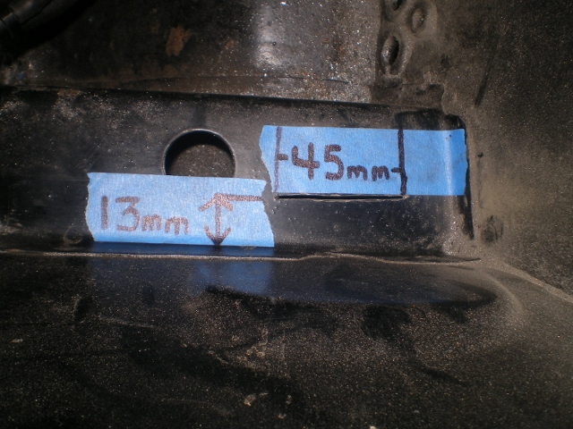
Well I guess we won't. Email bounced back to me. Onward thru the Fog. I picked up a used front sway bar. Sandblasted it, some new bushings, some paint and it gets another life. Looking down on the right side with the tank out you will see the raised flat area that needs to be trimmed. I found the appx center on the round flat aea where the mount is located then made a cut 45mm long (22.5mm either side of center) and 13mm away from the edge as shown. Clear as mud, huh?
 Then a few holes on each end. 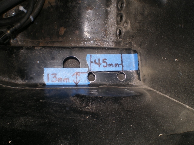 Then with a large punch I beat this piece down and flush with the wall. 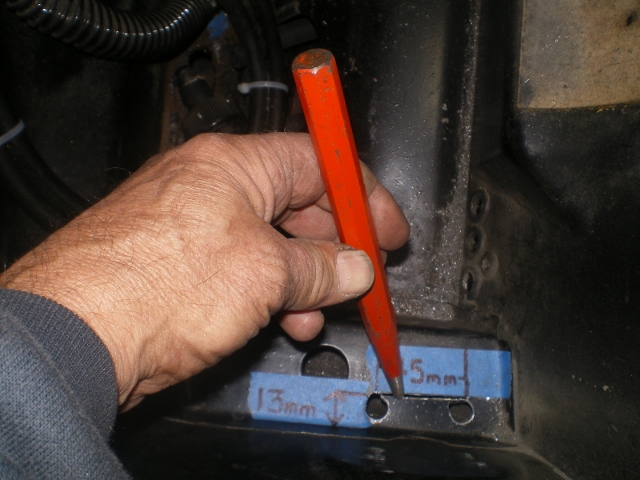 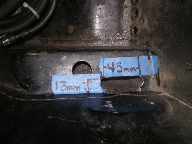 Then back inside the wheel well I measured over from the brake line brace to locate center. Don't confuse this 45mm mark with the one inside. They overlap but are staggered. 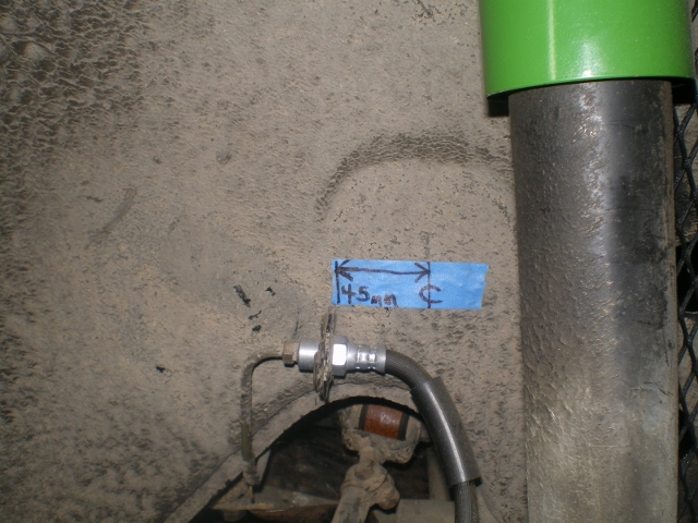 Then down 13mm from the arch to locate the top of the "inside" brace. The plate that goes inside the wheel well is not the same shape. The bolt pattern is the same. And the infamous "too big" pic on Pelican was for the interior brace so thought I'd mention that. This is why I used that piece to mark the holes later. 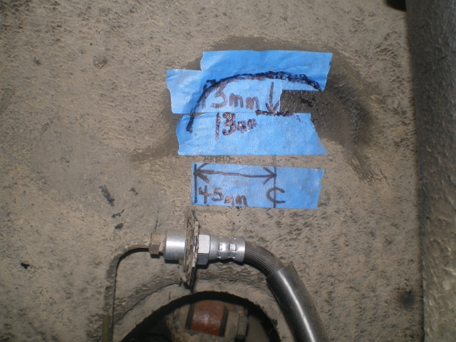 Again, referring to Pelican's article I located and drilled the front upper bolt first. 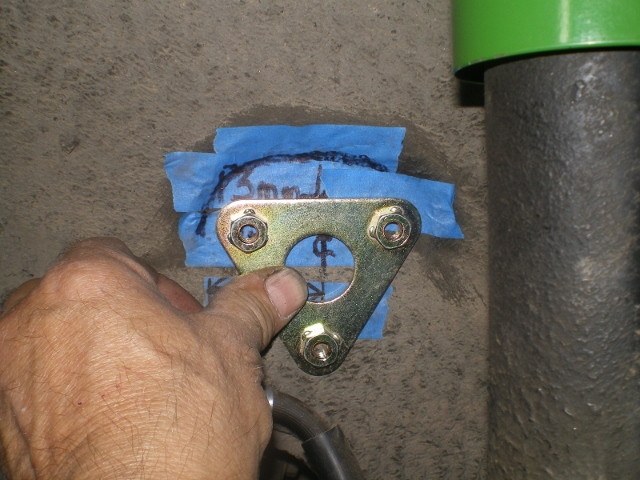 Drilled a small hole from this side 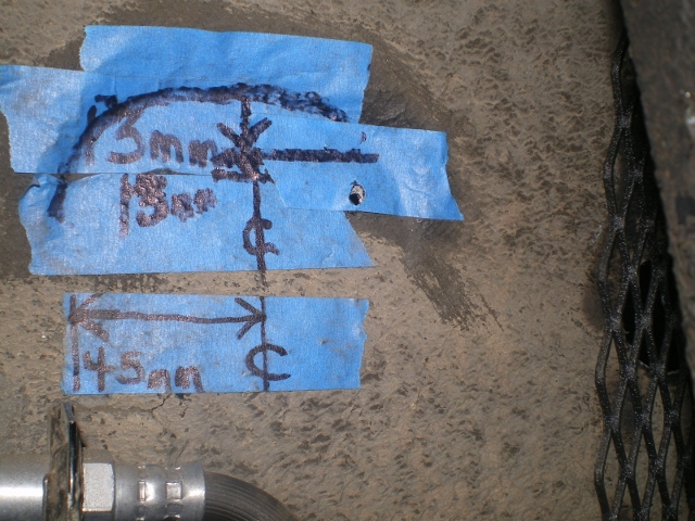 Finished this small hole up to 8mm 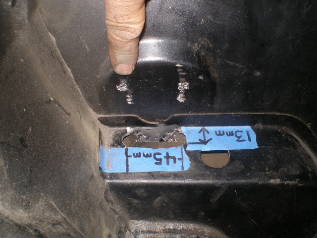 Then back inside the well to install this piece and locate/drill the remaining holes. 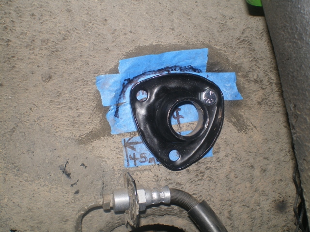 With the 3 bolts installed and in place I can see the center mark and mark and center punch where the 1" hole goes. 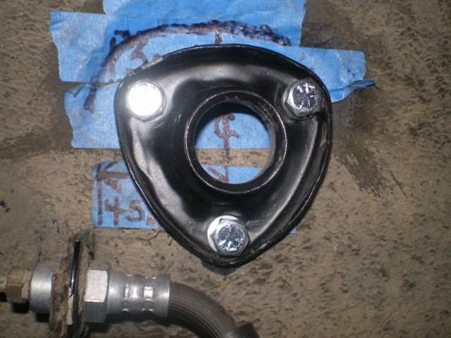 With the center pilot hole drilled out the hole punch is put to use. A shot from both sides. 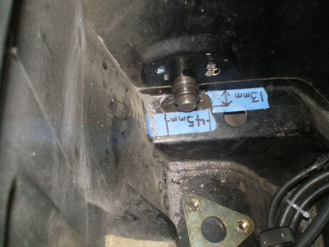 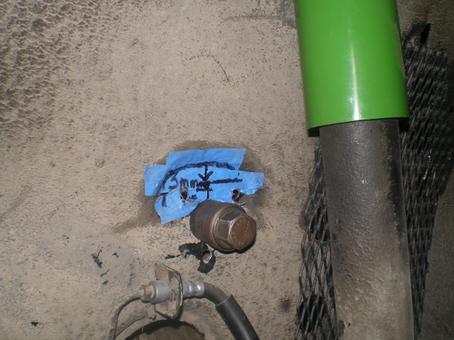 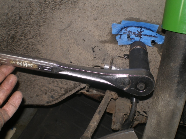 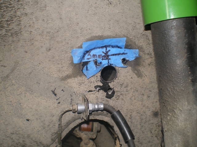 Here are some shots showing how the radiator hose just clears all this in the left wheel well. Btw, all this comes back out for some quick paint and I ordered the wrong size bushings so I'm awaiting those. 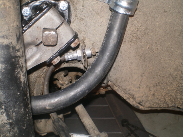 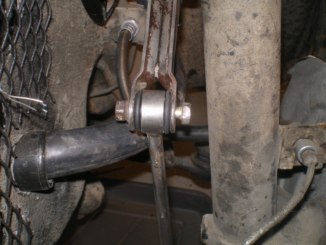 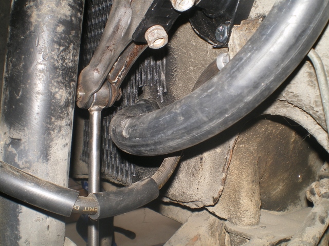 It occurred to me that this may be the last time this tank is out (IMG:style_emoticons/default/av-943.gif) (IMG:style_emoticons/default/lol-2.gif) (IMG:style_emoticons/default/laugh.gif) so I thought I would put some gas in it to see what leaks before hand. 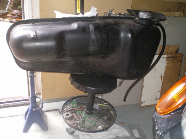 EDIT: Forgot to ask this. When I weld the inner brace to the well do I spot or seam weld it? TIA, Kent |
|
|
|
| CptTripps |
Mar 3 2014, 09:36 AM
Post
#279
|
|
:: Punch and Pie :: Group: Members Posts: 3,586 Joined: 26-December 04 From: Tuscaloosa, AL and Akron, OH Member No.: 3,342 Region Association: Upper MidWest |
Awesome progress Kent.
I was going to weld up the two bottom lined on my stock tank too, since I'll be using the Subaru feeder/pump. I may cut a bigger hole in the bottom first so I can make sure the feeder is all the way at the bottom. Something to remember: Only put a LITTLE fuel in at first. After you get your gauges set up, you'll need to know how many gallons you have left when the "feed me" light goes on. I always start with 1-gal, and then add it in 1/2-gal increments until the wife/kid inside the car says "It's off!" That gives me an idea of how long I have. |
|
|
|
| 76-914 |
Mar 3 2014, 10:14 AM
Post
#280
|
|
Repeat Offender & Resident Subaru Antagonist Group: Members Posts: 13,905 Joined: 23-January 09 From: Temecula, CA Member No.: 9,964 Region Association: Southern California |
QUOTE(CptTripps @ Mar 3 2014, 07:36 AM) Awesome progress Kent. I was going to weld up the two bottom lined on my stock tank too, since I'll be using the Subaru feeder/pump. I may cut a bigger hole in the bottom first so I can make sure the feeder is all the way at the bottom. Something to remember: Only put a LITTLE fuel in at first. After you get your gauges set up, you'll need to know how many gallons you have left when the "feed me" light goes on. I always start with 1-gal, and then add it in 1/2-gal increments until the wife/kid inside the car says "It's off!" That gives me an idea of how long I have. Thx Doug or should I say, "Et tu, Brutus". I have this feeling yours will be on the road (and nicer) than mine. (IMG:style_emoticons/default/sad.gif) BTW, beginning w/ post #131 and you will see that you can see the position of the Suby fuel pick up thru the "new" fuel sender location. That's a good tip on low fuel warning. |
|
|
|
|
1 User(s) are reading this topic (1 Guests and 0 Anonymous Users)
0 Members:

|
Lo-Fi Version | Time is now: 25th June 2026 - 04:22 AM |
Invision Power Board
v9.1.4 © 2026 IPS, Inc.