|
|
|
Porsche, and the Porsche crest are registered trademarks of Dr. Ing. h.c. F. Porsche AG.
This site is not affiliated with Porsche in any way. Its only purpose is to provide an online forum for car enthusiasts. All other trademarks are property of their respective owners. |
|
|

  |

| Bob L. |
 Jan 17 2013, 11:33 AM Jan 17 2013, 11:33 AM
Post
#1
|
|
Senior Member  Group: Members Posts: 847 Joined: 7-August 11 From: Austin TX Member No.: 13,411 Region Association: Southwest Region |
1) I have searched around for a torque setting to install new step studs for the exhaust manifold/header. The only setting I can find is from Tunacan.net.
They list - heat exchangers to cylinder head at 16 ftlbs. Does this apply to installing the stud in the case, the nut on the stud(holding the header) or both? Any pertinent info would appreciated as well. 2) I'm having trouble matching the vacuum hose diagram to the ports i have on my engine. A '76 2.0. The diagram shows 3 connections at the throttle body. 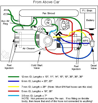 However, my throttle body only has one connection. I see where one can be eliminated. (IMG:style_emoticons/default/confused24.gif) Is the '76 different? Please advise. Thanks. |
   |

 
|
| SLITS |
Jan 17 2013, 11:56 AM
Post
#2
|
|
"This Utah shit is HARSH!" Group: Benefactors Posts: 13,602 Joined: 22-February 04 From: SoCal Mountains ... Member No.: 1,696 Region Association: None |
Your '75 will have only one port on the throttle body and it is connected to the Vacuum Retard on the distributor. Vacuum Advance was not used after '73. There are only two anyway. The blue line you see is from a port on the air cleaner to the De-acceleration valve ... adds extra air for emission control on closed throttle. Your '75, if equipped with the smog pump originally, will have a rectangular fitting to which a tube was fastened.
There is no torque value that I am aware of for installing studs in the heads that I am aware of. Since they are threaded on both ends with a gap in the middle, I run the short threaded end into the boss until it hits the gap. I do torque the nuts that hold the HEs on to the value specified; Why studs? Once in, they are less prone to pulling threads out of aluminum (unless over-torqued) than running a threaded fastener(bolt) in and give better clamping force. My opinion ... the "spurts" can chime in now. |
|
|
|
| gunny |
Jan 17 2013, 01:34 PM
Post
#3
|
|
Member Group: Members Posts: 205 Joined: 17-October 12 From: Madison Al Member No.: 15,051 Region Association: South East States |
The diagram is hard to follow, I just went through this on my 1976 2.0.
There are 2 lines to the throttle Body both going to the distributor as drawn the other line that looks like it goes to the TB is actually the air cleaner. |
|
|
|
| 442nd914s |
Jan 17 2013, 02:45 PM
Post
#4
|
|
Member Group: Members Posts: 139 Joined: 25-July 12 From: KC Suburb Member No.: 14,718 Region Association: None |
QUOTE(gunny @ Jan 17 2013, 01:34 PM)  The diagram is hard to follow, I just went through this on my 1976 2.0. There are 2 lines to the throttle Body both going to the distributor as drawn the other line that looks like it goes to the TB is actually the air cleaner. (IMG:style_emoticons/default/agree.gif) I had to go under the "originality forum" here and look under the engine bay pictures to get the hoses right. That diagram has a couple of mistakes. No offense to the person. I also have a 2.0lt efi |
|
|
|
| gunny |
Jan 17 2013, 02:52 PM
Post
#5
|
|
Member Group: Members Posts: 205 Joined: 17-October 12 From: Madison Al Member No.: 15,051 Region Association: South East States |
QUOTE(442nd914s @ Jan 17 2013, 12:45 PM) QUOTE(gunny @ Jan 17 2013, 01:34 PM) The diagram is hard to follow, I just went through this on my 1976 2.0. There are 2 lines to the throttle Body both going to the distributor as drawn the other line that looks like it goes to the TB is actually the air cleaner. (IMG:style_emoticons/default/agree.gif) I had to go under the "originality forum" here and look under the engine bay pictures to get the hoses right. That diagram has a couple of mistakes. No offense to the person. I also have a 2.0lt efi The diagram is from a 73-early 74 2.0. I can't find any diagrams of a 1976 vacuum setup. If your looking for the 2 vacuum lines to the TB this diagarm is correct for those 2, atleast that is how mine is setup withe EFI. |
|
|
|
|
1 User(s) are reading this topic (1 Guests and 0 Anonymous Users)
0 Members:

|
Lo-Fi Version | Time is now: 21st May 2024 - 09:50 AM |
Invision Power Board
v9.1.4 © 2024 IPS, Inc.