|
|
|
Porsche, and the Porsche crest are registered trademarks of Dr. Ing. h.c. F. Porsche AG.
This site is not affiliated with Porsche in any way. Its only purpose is to provide an online forum for car enthusiasts. All other trademarks are property of their respective owners. |
|
|

  |

| moggy |
 Jul 8 2013, 02:39 PM Jul 8 2013, 02:39 PM
Post
#21
|
|
Member  Group: Members Posts: 192 Joined: 15-December 04 From: Wales Member No.: 3,285 |
QUOTE(john rogers @ Jul 7 2013, 05:28 PM)  Some things to remember about dry sump systems. - They are not cheap, the use of braided Earl's -12 lines alone is a large expense. A top of the line cooler is not cheap either. - The suction pump has to be higher capacity that the pressure pump and when you get above 4K RPM the crankcase will usually become under a vacuum. The valve cover gaskets will need to be held in place or they can get sucked loose so most times a vent is added to each valve cover. - The oil level in the sump tank has to be figured when hot and level, much like a regular Porsche dry sump in a 911, otherwise the oil will find a way to blow out the sump tank. - Which brings us to a puke tank, it needs to be large and able to handle blow by if the oil level gets too high. Good luck Thanks John I've ordered a pump from Thorsten Pieper (similar design to CB one but bigger and better). I already have a quality front mount cooler and remote filter in the front boot. I can't buy an off the shelf tank (3 gallon) that will fit anywhere suitable, so I'm having someone make me a custom one that will fit in the engine bay just behind my seat. |
   |

 
|
| moggy |
Jul 8 2013, 02:42 PM
Post
#22
|
|
Member Group: Members Posts: 192 Joined: 15-December 04 From: Wales Member No.: 3,285 |
QUOTE(moggy @ Jun 28 2013, 10:42 AM) Quick question..... What do I do with the current oil in/out? Currently they are just to the right of the old oil filter take off. Do I simply just block them off like in the below photo? (IMG:http://www.914world.com/bbs2/uploads_offsite/images.thesamba.com-3285-1372444935.1.jpg) Unless I missed something, I'm still looking for an answer to this question. Also note that the oil filter take off on my engine is not like the above example engine photo - it has a block off plate on it (not sure if that makes any difference). Thanks again for everyone's help on this - always learning (IMG:style_emoticons/default/smile.gif) |
|
|
|
| ChrisFoley |
Jul 8 2013, 03:54 PM
Post
#23
|
|
I am Tangerine Racing Group: Members Posts: 8,012 Joined: 29-January 03 From: Bolton, CT Member No.: 209 Region Association: None |
You will need to loop them together, not block them off.
Otherwise the pressure pump will hit a dead end and no oil will go to the bearings. Another option would be to make a passage in the filter blockoff plate and plug the ports as in the picture. |
|
|
|
| moggy |
Jul 9 2013, 03:17 PM
Post
#24
|
|
Member Group: Members Posts: 192 Joined: 15-December 04 From: Wales Member No.: 3,285 |
QUOTE(Racer Chris @ Jul 8 2013, 01:54 PM) You will need to loop them together, not block them off. Otherwise the pressure pump will hit a dead end and no oil will go to the bearings. Another option would be to make a passage in the filter blockoff plate and plug the ports as in the picture. Awesome Chris. That's exactly what I needed to know and confirms what I suspected. I'll try to source a block off plate that has some pass through machined into it. Thanks |
|
|
|
| moggy |
Jul 9 2013, 04:09 PM
Post
#25
|
|
Member Group: Members Posts: 192 Joined: 15-December 04 From: Wales Member No.: 3,285 |
QUOTE(Racer Chris @ Jul 8 2013, 01:54 PM) You will need to loop them together, not block them off. Otherwise the pressure pump will hit a dead end and no oil will go to the bearings. Another option would be to make a passage in the filter blockoff plate and plug the ports as in the picture. This should do it I reckon..... http://www.machine7.com/product.php?xProd=241&xSec=103 |
|
|
|
| ChrisFoley |
Jul 9 2013, 06:28 PM
Post
#26
|
|
I am Tangerine Racing Group: Members Posts: 8,012 Joined: 29-January 03 From: Bolton, CT Member No.: 209 Region Association: None |
That looks like just the ticket.
|
|
|
|
| moggy |
Dec 8 2013, 02:59 PM
Post
#27
|
|
Member Group: Members Posts: 192 Joined: 15-December 04 From: Wales Member No.: 3,285 |
QUOTE(bam914 @ Jun 24 2013, 07:43 AM) It was over $400.00. He is in Germany. You do need to modify the engine mount. Are you on Facebook? I can contact him there. Hi Blake Finally got to the stage of fitting this now. Tank is in, pump is in. Now to the stage of making modded engine mounts. Got any photos of what you did here before I start going down a certain route. Cheers Moggy |
|
|
|
| bam914 |
Dec 9 2013, 09:44 PM
Post
#28
|
|
Member Group: Members Posts: 342 Joined: 23-November 03 From: Atlanta, Ga Member No.: 1,378 Region Association: None |
QUOTE(moggy @ Dec 8 2013, 01:59 PM) QUOTE(bam914 @ Jun 24 2013, 07:43 AM) It was over $400.00. He is in Germany. You do need to modify the engine mount. Are you on Facebook? I can contact him there. Hi Blake Finally got to the stage of fitting this now. Tank is in, pump is in. Now to the stage of making modded engine mounts. Got any photos of what you did here before I start going down a certain route. Cheers Moggy Never got to that point. Sorry |
|
|
|
| moggy |
Dec 11 2013, 05:39 AM
Post
#29
|
|
Member Group: Members Posts: 192 Joined: 15-December 04 From: Wales Member No.: 3,285 |
QUOTE(bam914 @ Dec 9 2013, 07:44 PM) Never got to that point. Sorry No worries (IMG:style_emoticons/default/beerchug.gif) So, last night I made a start on making some custom mounts to work around the pump. This is what we're up against.... I've used some pipe tails that I had lying around to give me an idea of what I need to work around, as you can see below the in/out is exactly where the standard engine mounts would normally sit. (IMG:http://www.914world.com/bbs2/uploads_offsite/i31.photobucket.com-3285-1386761987.1.jpg) I laid the engine bar and mounts in front so you can see exactly the issues (IMG:http://www.914world.com/bbs2/uploads_offsite/i31.photobucket.com-3285-1386761987.2.jpg) So first thing to do is cut off the mounts from the back plate, so I can mount them below the in/out of the pump. Firstly I had to measure how far the hole is from the backplate to ensure that when it's all welded back on it's the same distance from the engine. Works out a touch over an inch... (IMG:http://www.914world.com/bbs2/uploads_offsite/i31.photobucket.com-3285-1386761988.3.jpg) and a touch of centre from the top mount hole (IMG:http://www.914world.com/bbs2/uploads_offsite/i31.photobucket.com-3285-1386761988.4.jpg) Next job is to cut the mounts off the back plate so the back plates look like the below. I tried to do it so that the cutting disk was as close to the backing plate as possible and I didn't eat into the mount too much, reason is because I want to re-use the mount when I weld it on later. Eating too much out of it with the cutting disk when cutting it off the backplate will mean it will sit too far back when welding it back on. (IMG:http://www.914world.com/bbs2/uploads_offsite/i31.photobucket.com-3285-1386761988.5.jpg) So now the back plates sit comfortably behind the pump. I've also placed the engine bar in the position it needs to sit in relation to the engine when in the car (IMG:http://www.914world.com/bbs2/uploads_offsite/i31.photobucket.com-3285-1386761988.6.jpg) Next step tonight is to start with tacking the mounts in the new lower location. Here's some pictures I took while I was at it of the mod to the fan shroud and how much space there is behind it for the pipe tails. (IMG:http://www.914world.com/bbs2/uploads_offsite/i31.photobucket.com-3285-1386761988.7.jpg) (IMG:http://www.914world.com/bbs2/uploads_offsite/i31.photobucket.com-3285-1386761988.8.jpg) (IMG:http://www.914world.com/bbs2/uploads_offsite/i31.photobucket.com-3285-1386761988.9.jpg) (IMG:http://www.914world.com/bbs2/uploads_offsite/i31.photobucket.com-3285-1386761989.10.jpg) Sorry for poor quality shots taken with my phone but photography is not a strong point (IMG:style_emoticons/default/biggrin.gif) |
|
|
|
| Borderline |
Dec 11 2013, 12:30 PM
Post
#30
|
|
Senior Member Group: Members Posts: 720 Joined: 8-February 05 From: San Juan Bautista, CA Member No.: 3,577 Region Association: Northern California |
It's been a while since I did my engine build, but I remember the Type 4 oil pump being slight larger in diameter than the Type 1. I bought a pump from fat Performance that had an O-ring placed around the body to seal in the case. Are there oil pumps now that are designed for Type 4 engines? If not, how are you handling the size difference in pumps?
|
|
|
|
| yeahmag |
Dec 11 2013, 12:48 PM
Post
#31
|
|
Advanced Member Group: Members Posts: 2,468 Joined: 18-April 05 From: Pasadena, CA Member No.: 3,946 Region Association: Southern California |
I used a single peace of strong angle iron and only captured the bottom two mount holes. It's a single piece and the engine bar is mounted directly to it with some heavy duty, thin isolating material I got from a buddy in the hydraulics business.
It's damn near impossible to see in this picture, but if you look close it's there. 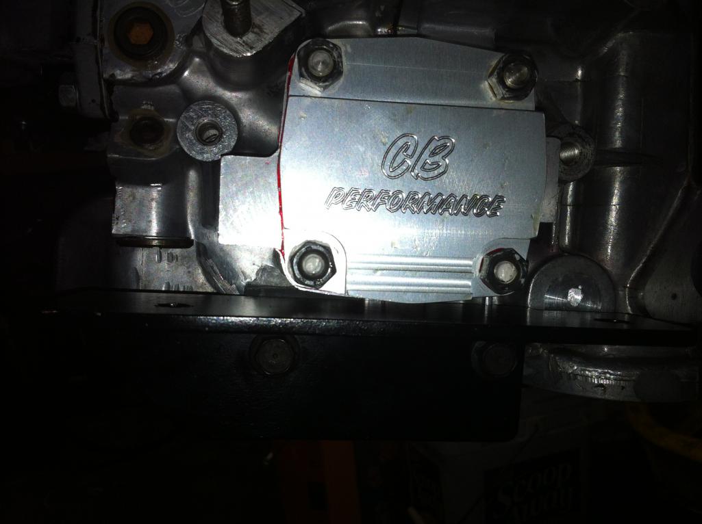 |
|
|
|
| moggy |
Dec 12 2013, 09:02 AM
Post
#32
|
|
Member Group: Members Posts: 192 Joined: 15-December 04 From: Wales Member No.: 3,285 |
Aaron - I looked at that option but decided against it for a number of reasons:
1 - The engine/gearbox needs to be really held in as strong as possible in the rallycar, all that heavy vibration and big hits really tests all mounting points out to the limit. For this reason I didn't feel comfortable only holding it all in on just the bottom 2 bolt holes 2 - With the vibrations experienced in rallying I wanted to have some kind of rubber seated engine mounts to absorb at least some of the pounding. 3 - I couldn't see how a straight bar was going to allow me to avoid the gear linkage. For these reasons I went with the standard engine bar and modded mounts. Last night I managed to find some good solid rubber machinery mounts that are ideal as engine mounts, they're even the same diameter - what are the chances of that eh? (IMG:style_emoticons/default/biggrin.gif) (IMG:http://www.914world.com/bbs2/uploads_offsite/i31.photobucket.com-3285-1386860525.1.jpg) Using the mounts I cut of the back plates last night, I offered them up and found a problem on the right hand side - it now knocks into the old oil filler blockoff as you can see (the engine I'm using to mock everything up does not have the blockoff plate on, as you can see, but believe me it knocks into it). This means I'm going to need to shave off about 10mm from the right side of the mount to get it to fit. (IMG:http://www.914world.com/bbs2/uploads_offsite/i31.photobucket.com-3285-1386860525.2.jpg) On the left side, all is well, although I'll still shave off 10mm to match the other side. Whilst at this point I checked measurement away from the backplate again to ensure it's all still at the smidge over 1 inch. Still looking good. (IMG:http://www.914world.com/bbs2/uploads_offsite/i31.photobucket.com-3285-1386860526.3.jpg) You'll notice in the above to shots that there's gap between the mount and back plate, this was from the amount of metal the cutting disk bit out when I cut the mounts off the back plates earlier in the process. To fill in this gap and to also add strength to the mounts in their lower postions it's necessary to weld in a small additional plate, as you can see below: (IMG:http://www.914world.com/bbs2/uploads_offsite/i31.photobucket.com-3285-1386860526.4.jpg) (IMG:http://www.914world.com/bbs2/uploads_offsite/i31.photobucket.com-3285-1386860526.5.jpg) And here's where we're up to at the moment. All tacked up roughly. Offered it up to the engine bar. All fits perfectly. Next steps - weld up what I have, clean it up, maybe add another strengthening gusset. (IMG:http://www.914world.com/bbs2/uploads_offsite/i31.photobucket.com-3285-1386860972.1.jpg) That's all for now folks (IMG:style_emoticons/default/santa_smiley.gif) |
|
|
|
| pcar916 |
Dec 12 2013, 09:31 AM
Post
#33
|
|
Is that a Lola? Group: Members Posts: 1,524 Joined: 2-June 05 From: Little Rock, AR Member No.: 4,188 Region Association: None |
... as well you'll have to calculate the proper oil capacity. In other words, when does it need more, is it full, overfull? The 4 cylinder guys will chime in here. Six'ers check our oil levels in the tank. What about the fours? I've never considered that.
(IMG:style_emoticons/default/beerchug.gif) |
|
|
|
|
1 User(s) are reading this topic (1 Guests and 0 Anonymous Users)
0 Members:

|
Lo-Fi Version | Time is now: 23rd October 2025 - 04:43 PM |
Invision Power Board
v9.1.4 © 2025 IPS, Inc.