|
|
|
Porsche, and the Porsche crest are registered trademarks of Dr. Ing. h.c. F. Porsche AG.
This site is not affiliated with Porsche in any way. Its only purpose is to provide an online forum for car enthusiasts. All other trademarks are property of their respective owners. |
|
|

  |

| HalfMoon |
 Aug 9 2013, 06:07 PM Aug 9 2013, 06:07 PM
Post
#1
|
|
Senior Member  Group: Members Posts: 828 Joined: 13-November 12 From: Shenandoah Junction, WV Member No.: 15,144 Region Association: MidAtlantic Region |
In solving more problems for my 1973 v-8 converted 914, I need to hook up my back up lights (they were removed by the PO presumably during the conversion).
The switch is on the trans, but there's no wires to be found. When I examine the wiring diagram (picture enclosed) for a 1973, I see the wires run to the switch (from the lights) onto the trans switch then to a thing called #90 "Regulator plate". No idea what this is or where it's located and Haynes makes no mention of it. As a guess, is this part of the stock system on or near where the regulator would have been? From the "Regulator plate", wires then go to #35 stop lamp switch. Where is the regulator plate located and where is/was the regulator itself located? Thanks all :-) Btw, still working on the wiper problem. Switch suspected. 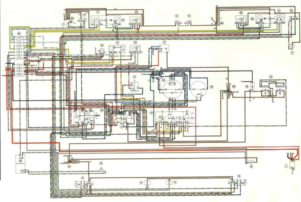 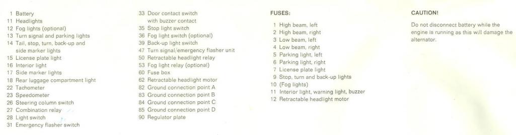 |
   |

 
|
| HalfMoon |
Aug 9 2013, 06:19 PM
Post
#2
|
|
Senior Member Group: Members Posts: 828 Joined: 13-November 12 From: Shenandoah Junction, WV Member No.: 15,144 Region Association: MidAtlantic Region |
QUOTE(HalfMoon @ Aug 9 2013, 08:07 PM)  In solving more problems for my 1973 v-8 converted 914, I need to hook up my back up lights (they were removed by the PO presumably during the conversion). The switch is on the trans, but there's no wires to be found. When I examine the wiring diagram (picture enclosed) for a 1973, I see the wires run to the switch (from the lights) onto the trans switch then to a thing called #90 "Regulator plate". No idea what this is or where it's located and Haynes makes no mention of it. As a guess, is this part of the stock system on or near where the regulator would have been? From the "Regulator plate", wires then go to #35 stop lamp switch. Where is the regulator plate located and where is/was the regulator itself located? Thanks all :-) Btw, still working on the wiper problem. Switch suspected. Evidently the "regulator plate" is also known as a "circuit board" (picture enclosed). My PO removed it. Soooo, from reverse light switch on the trans, I wonder if it would be possible to get power from the brake light switch which is where it went after the circuit board (on a 914 with a circuit board/regulator plate)? 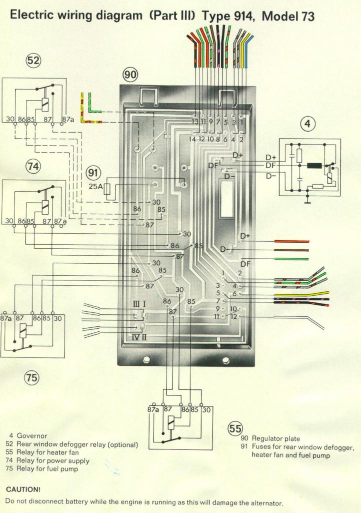 |
|
|
|
| JeffBowlsby |
Aug 9 2013, 06:22 PM
Post
#3
|
|
914 Wiring Harnesses & Beekeeper Group: Members Posts: 8,974 Joined: 7-January 03 From: San Ramon CA Member No.: 104 Region Association: None |
AKA relay board. Drivers side engine bay on a shelf, should have a black plastic molded cover and the main chassi harness connects to the board via a 14 pin connector plug. The back-up lights have 2 wires that are in the ignition harness...which connects to the relay board (12 pin connector) and starter. Your car is modified so only you will know what has been modified or removed.
|
 |
|
| HalfMoon |
Aug 9 2013, 06:33 PM
Post
#4
|
|
Senior Member Group: Members Posts: 828 Joined: 13-November 12 From: Shenandoah Junction, WV Member No.: 15,144 Region Association: MidAtlantic Region |
QUOTE(Jeff Bowlsby @ Aug 9 2013, 08:22 PM) AKA relay board. Drivers side engine bay on a shelf, should have a black plastic molded cover and the main chassi harness connects to the board via a 14 pin connector plug. The back-up lights have 2 wires that are in the ignition harness...which connects to the relay board (12 pin connector) and starter. Your car is modified so only you will know what has been modified or removed. Thanks Jeff. I checked the area you mentioned and indeed it has been removed. About the only thing I would have needed it for was the reverse lights :-( I wonder about going direct from the reverse light switch on the trans to the brake light switch direct (which is where it went had a circuit board been in place) Also, and as an aside, do you happen to know if a bad wiper swtch would kill power to fuse block position eight? Thanks a bunch! We're getting there :-) Hopefully soon I can get it inspected and start DRIVING! |
|
|
|
| Dave_Darling |
Aug 9 2013, 08:26 PM
Post
#5
|
|
914 Idiot Group: Members Posts: 15,200 Joined: 9-January 03 From: Silicon Valley / Kailua-Kona Member No.: 121 Region Association: Northern California |
Look at the white lines on the relay board diagram. See how they go from one connector to another? That's the path the current takes.
If you look carefully at the diagram, you'll see that the two gray/brown wires that plug into the 12-pin connector at the right rear simply go through the board to connect to the gray/brown wires in the 14-pin connector on the front of the board. So if you can find those wires, just hook one rear wire to one front wire, and the other rear wire to the other front wire. No problem. --DD |
|
|
|
| HalfMoon |
Aug 9 2013, 08:50 PM
Post
#6
|
|
Senior Member Group: Members Posts: 828 Joined: 13-November 12 From: Shenandoah Junction, WV Member No.: 15,144 Region Association: MidAtlantic Region |
QUOTE(Dave_Darling @ Aug 9 2013, 10:26 PM) Look at the white lines on the relay board diagram. See how they go from one connector to another? That's the path the current takes. If you look carefully at the diagram, you'll see that the two gray/brown wires that plug into the 12-pin connector at the right rear simply go through the board to connect to the gray/brown wires in the 14-pin connector on the front of the board. So if you can find those wires, just hook one rear wire to one front wire, and the other rear wire to the other front wire. No problem. --DD Your the MAN! (IMG:style_emoticons/default/pray.gif) |
|
|
|
|
1 User(s) are reading this topic (1 Guests and 0 Anonymous Users)
0 Members:

|
Lo-Fi Version | Time is now: 12th July 2025 - 07:01 AM |
Invision Power Board
v9.1.4 © 2025 IPS, Inc.